

Sears 917.285230 Owner's Manual

MODEL NO.
917.285230
,_UTION:
Read Rules for
Safe Operation
and instructions
Carefully
®Assembly
o Operating
® Maintenance
® Repair Parts
J
Prinled in U S A
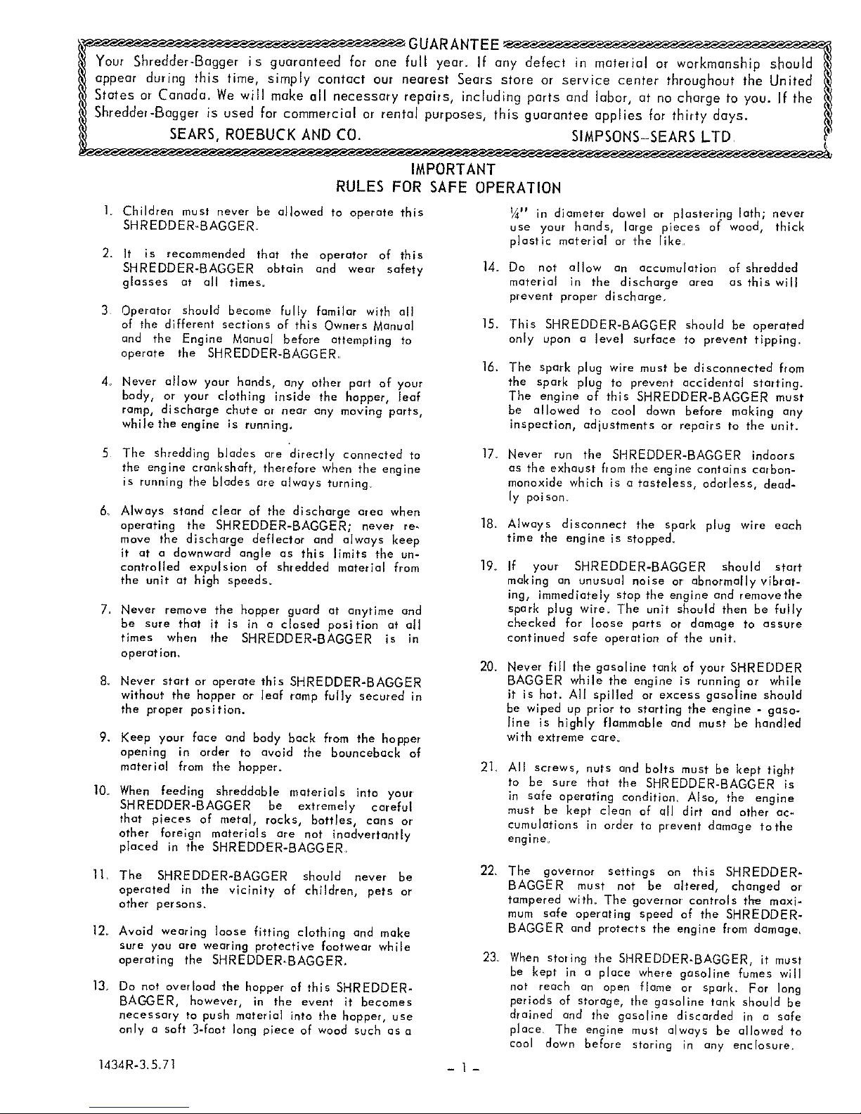
_GUARANTEE _
Your Shredder-Bagger is guaranteed for one fuji year. If any defect in material or workmanship should
appear during this time, simply contact our nearest Sears store or service center throughout the United
States or Conoda_ We will make all necessary repairs, including parts and labor, at no charge to you. If the
Shredder-Bagger is used for commercial or rental purposes, this guarantee applies for thirty days.
SEARS, ROEBUCK AND CO. SIMPSONS-SEARS LTD
IMPORTANT
RULES FOR SAFE OPERATION
1 Children must never be allowed to operate this
SHREDDER_BAGGER.
2. It is recommended that the operator of this
SHREDDER-BAGGER obtain and wear safety
glasses at all times.
3 Operator should become fully familar with all
of the different sections of this Owners Manual
and the Engine Manual before attempting to
operate the SHREDDER-BAGGER,
4o Never allow your hands, any other part of your
body, or your clothing inside the hopper, leaf
ramp, discharge chute or near any moving parts,
while the engine ;s running.
5 The shredding blades are "directly connected to
the engine crankshaft, therefore when the engine
is running the blades are always turning.
14.
15_
16.
17_
6_ Always stand clear of the discharge area when
operating the SHREDDER-BAGGER; never re- 18_
move the discharge deflector and always keep
it at a downward angle as this limits the un-
controlled expulsion of shredded material from 19o
the unit at high speeds.
7_ Never remove the hopper guard at anytime and
be sure that it is in a closed position at all
times when the SHREDDER-BAGGER is in
operatlon_
8_ Never start or operate this SHREDDER-BAGGER
without the hopper or leaf ramp fully secured in
the proper position.
20_
2I_
9. Keep your face and body back from the hopper
opening in order to avoid the bounceback of
material from the hopper_
10_ When feeding shreddable materials into your
SHREDDER-BAGGER be extremely careful
that pieces of metal, rocks, bottles, cans or
other foreign materials are not inadvertantly
placed in the SHREDDER-BAGGER.
¼" in diameter dowel or plasterlng lath; never
use your hands, large pieces of wood, thick
plastic material or the like
Do not allow an accumulation of shredded
material in the discharge area as this will
prevent proper discharge,
This SHREDDER-BAGGER should be operated
only upon a level surface to prevent tlpping_
The spark plug wire must be disconnected from
the spark plug to prevent accidental starting.
The engine of this SHREDDER-BAGGER must
be allowed to cool down before making any
inspection, adjustments or repairs to the unit.
Never run the SHREDDER-BAGGER indoors
as the exhaust from the engine contains carbon-
monoxide which is a tasteless, odorless, dead-
ly poison
Always disconnect the spark plug wire each
time the engine is stopped_
If your SHREDDER-BAGGER should start
making an unusual noise or abnormallyvibrat-
ing, immediately stop the engine and removethe
spark plug wire. The unit should then be fully
checked far loose parts or damage to assure
continued safe operation of the unlt_
Never fill the gasoline tank of your SHREDDER
BAGGER while the engine is running or while
it is hot. All spilled or excess gasoline should
be wiped up prior to starting the engine - gaso-
line is highly flammable and must be handled
with extreme care°
All screws, nuts and bolts must be kept tight
to be sure that the SHREDDER-BAGGER is
in safe operating condition, Also, the engine
must be kept clean of all dirt and other ac-
cumulations in order ta prevent damage tothe
engine.
11. The SHREDDER-BAGGER should never be
operated in the vicinity of children, pets or
other persons_
12_ Avoid wearing loose fitting clothing and make
sure you are wearing protective footwear while
operating the SHREDDER_BAGGER.
13, Do not overload the hopper of this SHREDDER-
BAGGER, however, in the event it becomes
necessary to push material into the hopper, use
only a soft 3-faot lanai piece of wood such as a
1434R-3,5_71
22_
23v
-I-
The governor settings on this SHREDDER-
BAGGER must not be altered, changed or
tampered wlth_ The governor controls the maxi-
mum safe operatlng speed of the SHREDDER-
BAGGER and protects the engine from damage_
When storing the SHREDDER-BAGGER, it must
be kept in a place where gasoline fumes will
not reach an open flame or spark. For long
periods of storage, the gasoline tank should be
drained and the gasoline discarded in a safe
place. The engine must always be allowed to
coal down before storing in any enclosure.
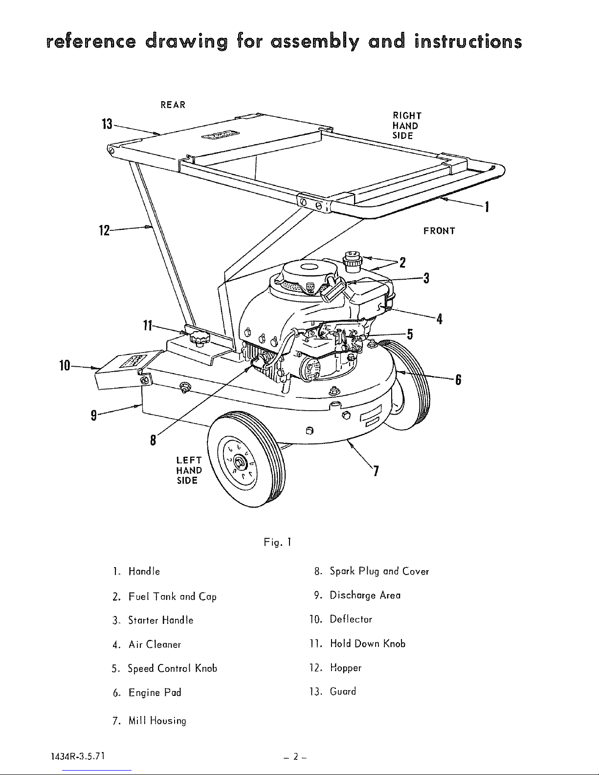
reference drawing for assembly and instructions
REAR
RIGHT
HAND
SIDE
/
FRONT
4
5
LEFT
HAND
SIDE
1. Handle
2. Fuel Tank and Cap
3_ Starter Handle
4. Air Cleaner
5_ Speed Control Knob
6_ Engine Pad
7. Mill Housing
Fig. 1
8. Spark Plug and Cover
9. Discharge Area
10. Deflector
11. Hold Down Knob
12. Hopper
13, Guard
1434R-3_5,71 - 2-
introduction
Your new SHREDDER-BAGGER utilizes multiple
sharp flat cutting blades rotating about the vertical
shaft of its engine within the mill housing_ In order
to reduce lawn and garden bulk by shredding, these
blades rotate at a speed of approximately 14,000
feet per minute or almost 158 miles per hour_ They
exert about the same force as a 7_ pound sledge
hammer traveling at 158 miles per hour and shred
materials by simply cutting and forcing them at this
speed against the internal breaker plates_ Ob-
viously, this extreme force constitutes a potential
danger if the SHREDDER-BAGGER is not properly
used and maintained_ It is therefore all the more
important that the operator always FOLLOW THE
"RULES FOR SAFE OPERATION" as well as
other instructions contained in the Owners Manual
and the Engine Manual
This SHREDDER-BAGGER has been designed,
engineered and manufactured to give you the best
passible dependability and performance. Should you
experience any minor problem which you cannot
easily remedy, please return your SHREDDER-
BAGGER to your nearest Sears, Roebuck and Co_
or Simpson-Sears Limited store_ They have well-
qualified, competent trained technicians and the
proper tools to service or repair this unit. NEVER
ATTEMPT TO REPAIR YOUR SHREDDER-BAGGER
UNLESS YOU ARE FULLY QUALIFIED TO DO SO.
assembly
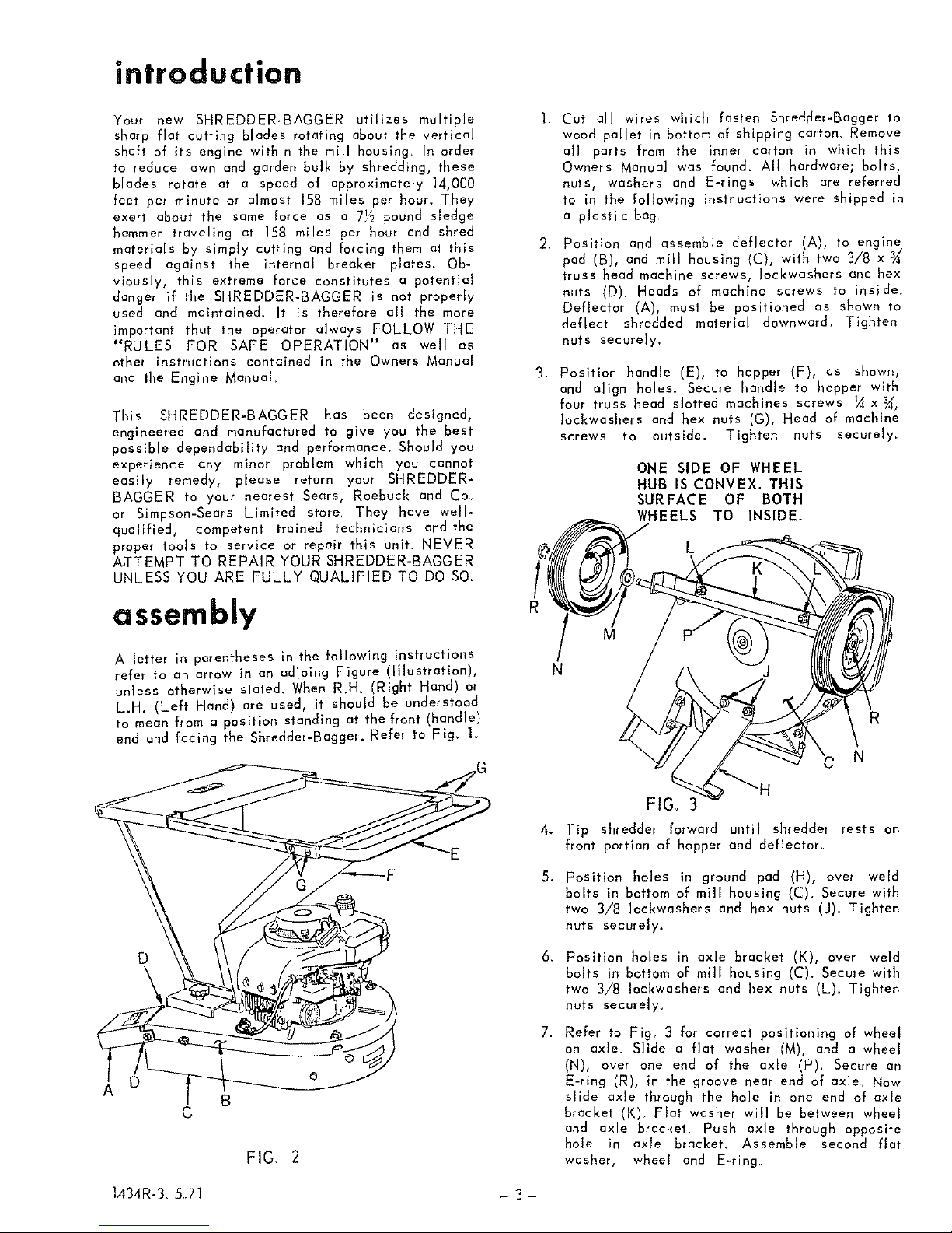
A letter in parentheses in the following instructions
refer to an arrow in an adjoing Figure (Illustration),
unless otherwise stated. When R.H. (Right Hand) or
L.H. (Left Hand) are used, it should be understood
to mean from a position standing at the front (handle)
end and facing the Shredder-Baggel. Refer to Fig_ t.
D o
C
FIG, 2
L434R-3, 571
.
-3-
3_
Cut all wires which fasten Shredder-Bagger to
wood pallet in bottom of shipping cartom Remove
all parts from the inner carton in which this
Owners Manual was found_ All hardware; bolts,
nuts, washers and E-rings which are referred
to in the following instructions were shipped in
a plastic bag.
Position and assemble deflector (A), to engine
pad (B), and mill housing (C), with two 3/8 x
truss head machine screws, Iockwashers and hex
nuts (D)_ Heads of machine screws to inside.
Deflector (A), must be positioned as shown to
deflect shredded material downward. Tighten
nuts securely.
Position handle (E), to hopper (F), as shown,
and align holes_ Secure handle to hopper with
four truss head slotted machines screws ¼ x¾,
Iockwashers and hex nuts (G), Head of machine
screws to outside. Tighten nuts securely.
ONE SIDE OF WHEEL
HUB IS CONVEX. THIS
SURFACE OF BOTH
WHEELS TO INSIDE.
L
N
R
N
4.
5_
6_
7.
FIG, 3
Tip shredder forward until shredder rests on
front portion of hopper and deflector_
Position holes in ground pad (H), over weld
bolts in bottom of mill housing (C)_ Secure with
two 3/8 Iockwashers and hex nuts (J). Tighten
nuts securely.
Position holes in axle bracket (K), over weld
bolts in bottom of mill housing (C). Secure with
two 3/8 Iockwashers and hex nuts (L). Tighten
nuts securely°
Refer to Fig. 3 for correct positioning of wheel
on axle. Slide a flat washer (M), and a wheel
(N), ovel one end of the axle (P). Secure an
E-ring (R), in the groove near end of axle. Now
slide axle through the hole in one end of axle
bracket (K). Flat washer will be between wheel
and axle bracket. Push axle through opposite
hole in axle bracket. Assemble second flat
washer, wheel and E-ring
 Loading...