

Sears 917. 270181 Owner's Manual
. -
....
(
--~·
[Sears~
,>-,':cJ°wners
_-
~-
/rilanuar~
·~
~-
..
'\,_1~
,.
,,
,"
.···
\
"'
...
) .
~;
<:;,
!.
~
..
~
~<
. D /
0
/~
.
.
...
·
- '
i
/~
--4
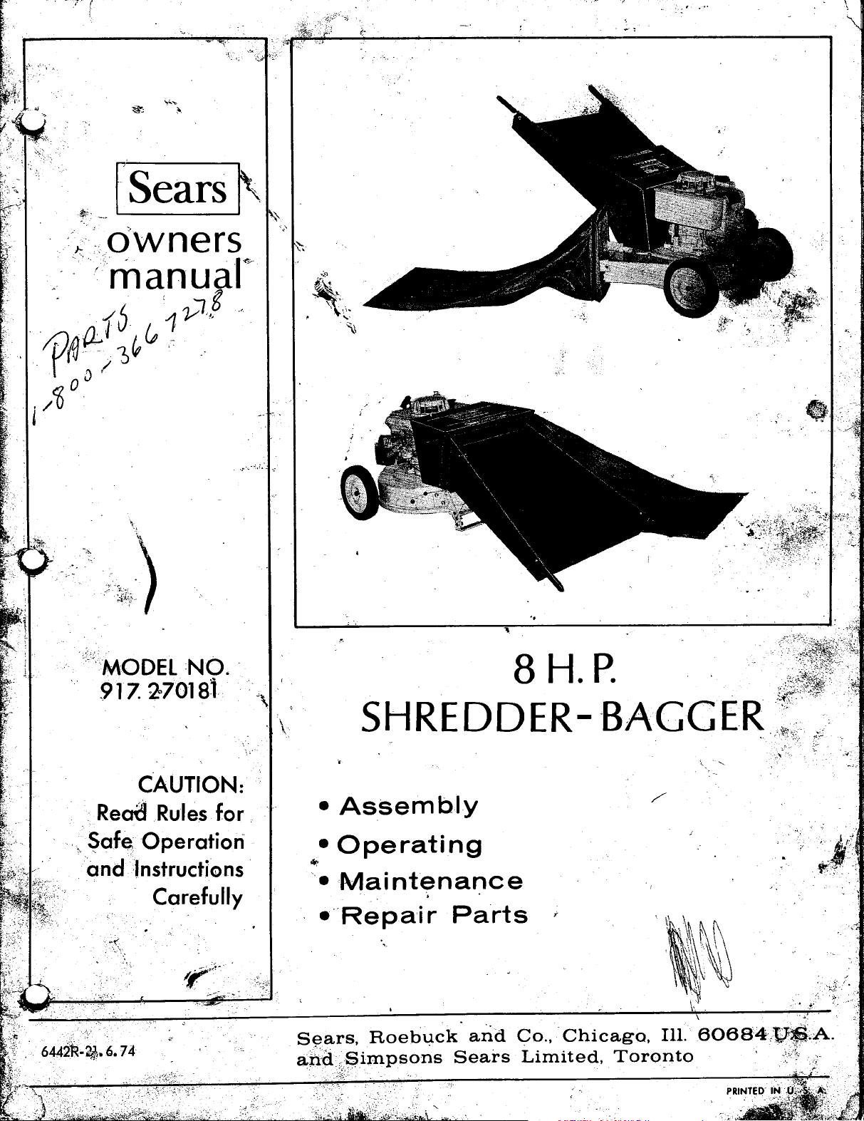
<<MODEL :NO. ·
917.
2'-70181
._
....
--:.:.
•:
. \
8 H.P.
SHREDDER-
-BAGGER.
-~.'
CAUTION:
Read
'·
~afe
and
Operation
·Instructions ·
Carefully
Rules
for
.
•Assembly
•Operating
~
•
Maintenance
··Repair
Sears,
ahcL$impsons
·.
·
....
:-
.
~-:~
~-;i_~~~L.&~t;.:;~:'{<~~-~M~>:
·)}_:'.
,_,._
Roebuck
..
~-·.
·,
.
Parts
arid
Sears
:.
.
_,
.·
Co.,·
.
Chicago,
Limited,
Ill.
Toronto
60684){)~;A.
.,,..
·

During
in
materia
any
of
days
if
the
I or
our
used
first
year,
workmanship.
stores
for
com mere
or
we
will
repair
Th
service
centers
i,a I purposes.
your
is
guarantee
Lawn
service
throughout
& Garden
is
available
the
United
Shredder-Bagger
by
simply
States
or
Canada.
w
\(!~j,'.~f~~'
free
of
charge,
returning
Guarantee
if
found
the
shredder-bagger
is I im
defective
ited
to
to
30
l.
The
operator
of
the
fore
2.
3.
4.
5.
. 6.
7.
8.
9.
10.
11.
12.
13.
14. Do
15.
16. It is
attempting
Children
Shredder-Bagger.
The
Shredder-Bagger
the
vicinity
The
Shredder-Bagger
base
is
located
Never
out
the
position
The
Shredding
the
Engine
gine
is
When
feeding
der-Bagger,
metal,-
ials
are
Always
time
the
The
Spark
the
Spark
Engine
to
cool
justments
If
the
foreign
J::..
Stop
B. Remove Spark
C.
Inspect
D.
Repair
restarting
All
screws,
be
sure
condition.
dirt
and
damage
If
your
unusual
stop
wire.
checked
tinued
Do
not
better
tended.
not
ger.
Do not
soft
wood
a
rate
R.
P.
Do
not
ial
to
prevent
recommended
der-Bagger
·times
17. Wear
6442R-29.
should
different
tight
near
start
Hopper
•
running,
rocks,
not
of your
down
blades
the
The
safe
job,
overload
M.'S.
allow
build
while
proper
4.
sections
must
disconnect
Engine
object,
Shredder-Bagger.
your
other
to
Shredder-Bagger
noise
for
force
that
proper
to
never
of
children,
in
place,
R.H.
or
operate
and
Blades
Crankshaft;
the
shreddable
be
extremely
bottles,
piaced
is
Plug
Wire
Plug
to
Shredder-Bagger
before
or
repairs
of your
follow
for
damage,
or
replace
your
nuts
Shredder-Bagger
Also
the
accumulations
Engine.
or
Engine
Shredder-Bagger
loose
operation.
your
safer,
the
feed_
'more
stick~
d'des
an
accumulation
up
in
discharge
obtain
operating
apparel,
7 4
SEARS,
become
operate
cannot
pivot
Ramp
Blades
in
the
stopped.
shou
prevent
to
Plug
Shredder-Bagger.
and
Engine
abnormal
and
parts
Shredder-Bagger,
at
hopper
at a time,
not
the
that
and
fully
of
this
this
be
a II
owed
shou
Id
never
pets
depressing
the
making
be
bracket.
your
Shredder-Bagger
secured
are
connected
therefore,
are
material
careful
can-5 or
the
Shredder-Bagger
these
any
bolts
disconnect
the
than
discharge
wear
this
Avoid
other
Shredder-Bagger.
Spark
Id
be
accidental
any
unit.
steps.
Wire.
damaged
must
is
must
in
should
vibration,
should
or
damage
rate
for
of your
two
Feed
substantially
and
the
operator
safety
machine.
wearing
ROEBUCK
IMPORTANT
RULES
familiar
Owners
Shredder-Bagger.
to
be
or
other
started
the
in
turning.
into
that
Plug
disconnected
must
inspection,
be
in
be
order
start
the
which
3/8
the
of
shredded
area
cause
with
Manual
operate
operated
persons.
unless
safety
switch
their
proper
directly
when
the
your
Shred-
pieces
foreign
starting.
safe
kept
then
to
Shredder-Bag-
inch
of
glasses
mater-
Wire
,
be
allowed
strike
parts
before
kept
tight
operating
clean
to
prevent
making
immediately
spark
be
as
sure
It
wi
II
it
is
diameter
machine
reduce
mater-
as
this
plugging.
this
Shred-
at
loose
fitting
AND
FOR
all
be-
this
in
the
with·
to
En-
of
every
from
The
ad··
any
to·
of
any
plug
fully
con-
do a
in-
at
the
will
all
CO. -SIMPSON-SEARS,
READ
SAFE
OPERATION
18.
19.
20.
21.
22.
23.
24.
25.
26.
27.
28.
29.
30.
I
'·
31.
~
32.
33.
- l -
clothing
wear
Never
body or
charge
gine
Keep
working
Always
ing your
justable
ward
discharged,
marked on
Keep
per
teria
Do
ance
Keep
accidents,
This
level
Do
operate
Never
exhaust
oxide
poison.
Never
Bagger
hot.
wiped
highly
treme
The
must
The
ing
the
Store
Shredder-Bagger
dry,
dren,
,
an
age,
olin_e
to
cool
Use
use
that
Stop
Wire when
changing
Use
Shredder-Bagger.
Maintain
keeping
operation,
or
while
operating
allow
clothing,
chute
is
running.
guards
order
stand
Shredder-Bagger.
Deflector
angle
to
the
your
face
opening
I.
not
at
not
All
governor
governor
speed
Engine
high
open
the
the
your
for
only
to
overreach.
all
times.
work
areas
machine
surface
expose
it
in
run your
from
which
..
fi
II
the
while
spilled
prior
to
flammable
care.
not
be
of
from
idle
tools
or
locked-up
Keep
where
flame
gasoline
discarded
before
right
Shredder-Bagger
which
Shredder-Bagger
not
accessories
Sears
your
it
clean
1ewelry,
your
and
The
wet
- , --·
altered,
LTD.
and
wear
your
Shredder-Bagger.
hands,
or
near
deflectors
to
assure
c I
ear
control
side
and
avo_id
should
to
prevent
your
or damp
Shredder-Bagger
the
is
tasteless,
gaso I ine
the
Engine
or
starting
and
settings
controls
the
damge,
indoors.
shou
or
spark.
tank
in a
storing
machine
it
is
in
use,
approved
Shredder-Bagger
or
inside
of
and
minimum
of
body
Keep
clean.
Engine
'""
excess
Shredder-Bagger
gasoline
intended.
for
any
the
any
moving
continued
discharge
Never remove
always
direction
the
Deflector.
back
the
bounce
proper
Cluttered
be
operated
tipping.
Shredder-Bagger
locations.
contains
·
tank
is
the
must
on
your
changed
the
maximum
When
Id
be
place,
For
should
safe
place.
in
any
for
the
for
and
before
such
as
accessori~s
best
protective
other
ramp-hopper,
parts
in
place
and
safe
area
keep
it
of
material
suggested
from
the
back
footing
areas
only
indoors
Carbon
odorless
of your
running or
gasoline
Engine.
be
,
stored
oyt
fumes
long
be
enclosure.
any
remove
servicing,
and
Gasoline
handled
Shredder-Bagger
or
tampered
safe
an#"protects
not
iri
indoors
of
reach
will
periods.of
drained
Allow
right
job.
purpose
Spark
plastic
'with
care
continued
foot·
part
of
your
dis·
while
En·
in good
operation.
·when
oper·
the
at
a down-
being
angle
ramp0hop•
of
any
ma•
and
bal·
invite
upon a
to
rain
as
the
Mon·
and
deadly
Shredder•
while
it
should
with
ex·
with.
operat-
-use,
your
in a
of
chil-
not
reach
stor·
and
gas•
Engine
Do
not
except
Plug
and
when
bag.
. _..__I
with
your
such
safe
ad-
or
be
is
as
is
is
g_
. ·
~
.
.,.
~
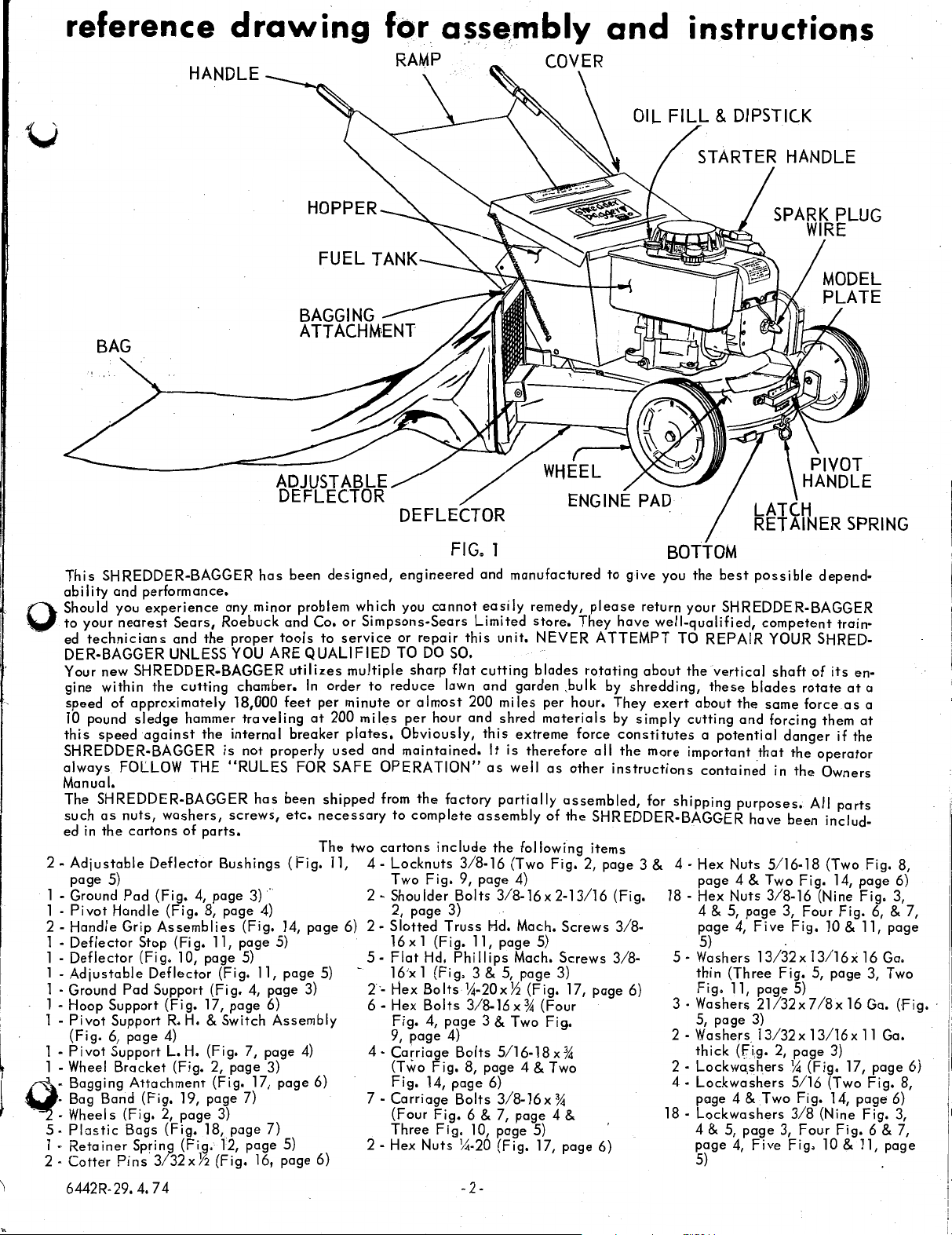
reference
u
BAG
drawing
for.
a~sembly
and
instructions
This
SHREDDER-BAGGER
ability
Should you
to
0
~
ed
DER-BAGGER UNLESS YOU
Your new SHREDDER-BAGGER
gine within
speed
10 pound
this
SHREDDER-BAGGER
always
Manual.
The SHREDDER-BAGGER
such
ed
2 -
l - Ground
l 2 l l l 1 - Ground
1 - Hoop Support
1 -
l 1 - Wheel
- Bagging
- Bag Band (Fig. 19, page 7) 7 -
- Wheels (Fig. 2,
5
·Plastic
l •
2
·Cotter
and
your
nearest
technicians
of
speed
FOLLOW THE
as
nuts,
in
the
Adjustable
page
5)
Pivot
Handle
Deflector
Deflector
Adjustable
Pivot
(Fig.
Pivot
Retainer
Pad
Handle
Grip
Pad
Support
6,
page
Support L.
Bracket
Bags
Pins
performance.
experience
Sears,
and
the
the
cutting
approximately
sledge
cartons
Attachment
Spring
hammer
against
Deflector
Stop
(Fig.
Deflector
Support
3/32xY2
the
washers,
of
parts.
(Fig,
4,
(Fig.
8,
Assemblies
(Fig.
10, page
(Fig.
(Fig.
17,
R.H.
& Switch
4)
H.
(Fig. 7, page
(Fig. 2, page 3) (Two
page
(Fig.
18,
(Fig.
has
been
any minor problem which you
Roebuck and
proper
internal
is
"RULES
screws,
Bushings
page
page
11, page 5)
(Fig. 11,
page
(Fig. 17,
3)
page
12,
(Fig.
tools
ARE
QUALIFIED
chamber.
18,000
traveling
not properly
(Fig.
5)
utilizes
feet
breaker
FOR
has
been
etc.
(Fig.
..
3)
· 2 - Shoulder
4) 2, page 3) · 4 & 5,
14,
page
4, page 3) 2·- Hex
6) 6 - Hex
Assembly
4)
page
7)
page
5) 2 - Hex
16, page 6) 5)
designed,
Co.
or
to
service
multiple
In
order
per
minute
at
200
plates.
used
SAFE
shipped
necessary
The
two
11,
page
6) 2 -
5)
6)
FIG.
engineered
Simpsons-Sears
to
miles
and
OPERATION"
from
cartons
4-
5 -
4 -
cannot
or
repair
TO
DO
SO.
sharp
reduce
or
per
Obviously,
maintained.
to
Locknuts
Two
Slotted
l6xl
Flat
16;x 1
Fig.
9,
Ca~riage
Fig.
Carriage
(Four
Three
flat
lawn
almost
hour
the
factory
complete
include
Fig.
Truss
(Fig.
Hd.
(Fig.
Bolts
Bolts
4,
page
page
4)
Fig.
14,
page
Fig.
Fig.
Nuts
l
and
manufactured
easily
Limited
this
cutting
and
200
and
this
assembly
3/8-16
9,
page
Bolts
11,
Phillips
3 & 5,
14-20xY:2
3/8-16
3 & Two Fig. 5, page
Bolts
8,
Bolts
6 & 7,
10,
14-20
remedy,
store.
unit.
NEVER
blades
garden ,bulk by
miles
per
shred
materials
extreme
It
is
therefore
as
well
as
partially
of
the
following
(Two
Fig,
4)
3/8-16x
Hd. Mach.
page
5/16-l8x
page
6) 4 - Lockwash.ers
3/8-16x%
page
(Fig.
2-13/16
5)
Mach.
page
3) thin (Three
(Fig.
x % (Four 3 - Washers 21732 x 7
4 & Two 2 - Lockwa,shers
page
4 & 18 -
5)
17,
to
please
They
have
ATTEMPT
rotating
hour.
They
by
force
constitutes a potential
all
the
other
instructions
assembled,
the
SHREDDER-BAGGER
items
2,
page
(Fig. 18 - Hex
Screws
Screws
17,
%
page
3/8-
3/8-
page
6)
BOTTOM
give
you
the
return your SHREDDER-BAGGER
well-qualified,
TO
REPAIR
about
shredding,
simply
6)
the
exert
about
cutting
more important
contain~d
for
shipping
3 & 4 - Hex Nuts
page
page
5) .
5 - Washers
Fig.
2-Washers.13/32xl3/16xll
thick
page
Lockwashers
4 & 5,
page
best
vertical
these
the
and
purposes,
4 & Two
Nuts
4,
11,
(f,ig. 2,
4 & Two
page
4,
possible
competent
YOUR SHRED-
shaft
blades
that
have
page
Five
13/32x
page
3)
Five
of
rotate
same
force
forcing them
danger
the
in
the
All
been includ-
5/16-18
Fig.
3/8-16
3, Four
Fig.
13/16x
Fig.
5, page 3, Two
5)
page
14
(Fig.
5/16
Fig.
3/8
3,
Four
Fig.
depend-
train·
its
en-
at
a
as
a
at
if
the
operator
Owners
parts
(Two
Fig.
14, page 6)
(Nine
Fig.
Fig.
10 & 11,
16 Ga.
/8
x 16 Ga.
3)
17,
(Two
14,
page
(Nine
Fig.
Fig.
10 & 11,
8,
3,
6, & 7,
page
(Fig.
Ga.
page
Fig.
8,
6)
3,
6 & 7,
page
·
6)
6442R·29. 4. 7 4
-2 -

table
"GUARANTEE
. #.
-RULES FOR SAFE OPERATION
ASSEMBLY INSTRUCTIONS
OPERATING
MAINTENANCE INSTRUCTIONS
REPAIR PARTS
of contents
3-7
7-10
10-13
15-23
tools required for assembly
~-·
of shredder-bagger
2 - 7
/16"
Wrenches
Yi"
1 1 -
1 1 -
Wrenches
9/16"
%"
Wrench
Pliers
Large
Large
Wrenches
slotted
phillips
screwdriver
screwdriver
2 2 -
assembly
A
letter
in
parenthesis
refers
tion),
Hand) or
derstood to mean
dles
to
an
arrow
unless
and facing the Shredder-Bagger. Refer to
Remove
ware:
which
were
washers,
bolts,
are
shipped
Bagger
L.
H.
all
parts
referred to
etc.,
from
carton.
otherwise
(Left Hand)
nuts,
in a
according to
in
the
following
in
an
adjoining
stated.
is
used,
from a position
from
both inner
washers,
in
plastic
Lay out
the
bag.
and
following
size.
all
Figure
When
it should be un·
standing
cartons.
cotter
Separate
Remove Shredder-
parts
for
A
instructions
(Illustra-
R.H.
(Right
at
the
han-
Fig.
1
All hard-
pins,
etc.
instruc~ions,
all
bolts,
assembly.
FIG. 3
2. Remove bottom from Shredder-Bagger. Refer
Fig.
3.
to
bottom·
hd.
phillips
nuts.
plastic
Assemble
(D)
Screws,
bag.
wheel
as
shown.
mach.
screws,
lockwashers,
Tighten
nuts
bracket
Use
securely.
(B) with
two
3/8-16x 1 flat
lockw'ashers, and hex
and hex
nuts
wheels
were
--------
E
FIG. 4
3. Refer to
ground pad support (F), with four
bolts,
holes
bag. Tighten
Fig.
lockwashers
as
shown.
nuts
4.
Assemble
and
hex
B~lts
etc.,
securely.
ground pad (E)
3/8-16x % hex
nuts
in
bottom two
were found in
plastic
to
in
•
to·
. l
B
;
c
F
l'. Refer to
bracket
two
and two
pression
in
outside
washers
6442R-29. 4. 7 4
(B)
13/32x
3/8
in
threads.
as
and
FIG. 2
Fig.
2.
Assemble
as
shown with two
13/16x
side
NOTE: Dimple
shown. Tighten
nuts
11
lockouts,
or end of nut, or a
were in
wheels
Ga.
(thickest)
Lockouts
at
nuts
plastic
(A)
shoulder
will
center
securely.
bag. .
to wheel
bolts_ (C),
flat
washers,
have a de·
plastic
of wheel
Bolts,
l3/32x
insert
to
13/16x
4. Refer to
16
Ga. washer
FIG. 5
Fig.
S.
Assemble
and ground pad to bottom
flat hd.
16 Ga.
(thinest)
as
las
p
phillips
flat
flat
shown.
tic
bag. Tighten
mach.
washers,
washers,
Screws,
washers,
three
ground pad
(D)
with
screw,
three
lockwashers,
13/32x
nuts
three
etc.,
securely._
support
three
3/8-16x
21/32x7/8x
13/16x
were found in
and
hex
16 Ga.
nuts,
(F),
1
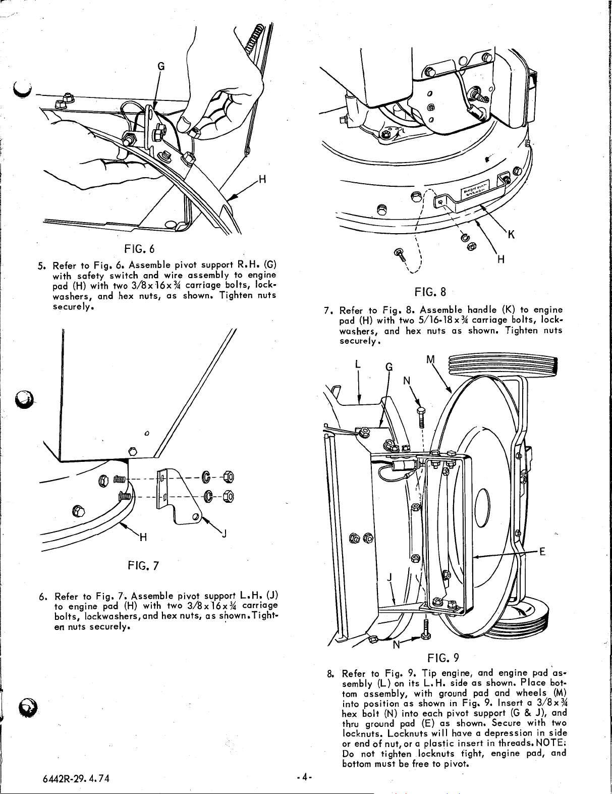
5.
Refer
to
with
safety
pad (H) with two
washers,
securely.
fig.
and
FIG. 6
6.
Assemble
switch
hex
G
and
3/8x
wire
16x % carriage
nuts,
as
pivot
assembly
shown.
support
bolts,
Tighten
·
R.H.
to
(G)
engine
lock-
nuts
7.
Refer
pad
washers,
securely.
I
\
\ I
~/
':
FIG. 8
to
Fig.
8.
(H)
with two 5/16-18 x %
and hex
Assemble
nuts
as
handle
carriage
shown.
H
(K) to
bolts,
Tighten
engine
lock-
nuts
6.
Refer to
to
engine
bolts,
en
nuts
H
FIG. 7
Fig.
7.
Assemble
pad
(H)
with two
lockwashers,and
securely.
-
--@--@
a---
pivot support
3/8x
hex
nuts,
-@--®
J
L.
l6x % carriage
as
shown.
'
H.
(J)
Tight-
L
0
6442R-29. 4. 7 4
-
4-
8. Refer to
sembly
tom
into
hex
thru ground pad (E)
locknuts.
or
end
Do
bottom
Fig.
(L) on
assembly,
position
bolt
(N)
Locknuts
of
nut, or a
not
tighten
must
FIG. 9
9.
Tip
engine,
its
L.
H.
side
as
with ground pad and
as
into
be
shown
locknuts
free
in
each
pivot
as
will have a
plastic
to pivot.
Fig.
shown.
insert
tight,
and
engine
shown.
9.
Insert a 3/8x
support
Secure
depression
in
threads.
engine
pad
Place
wheels
(G
& J), and
with two
pad,
'asbot·
(M)
in
side
NOTE:
and
%
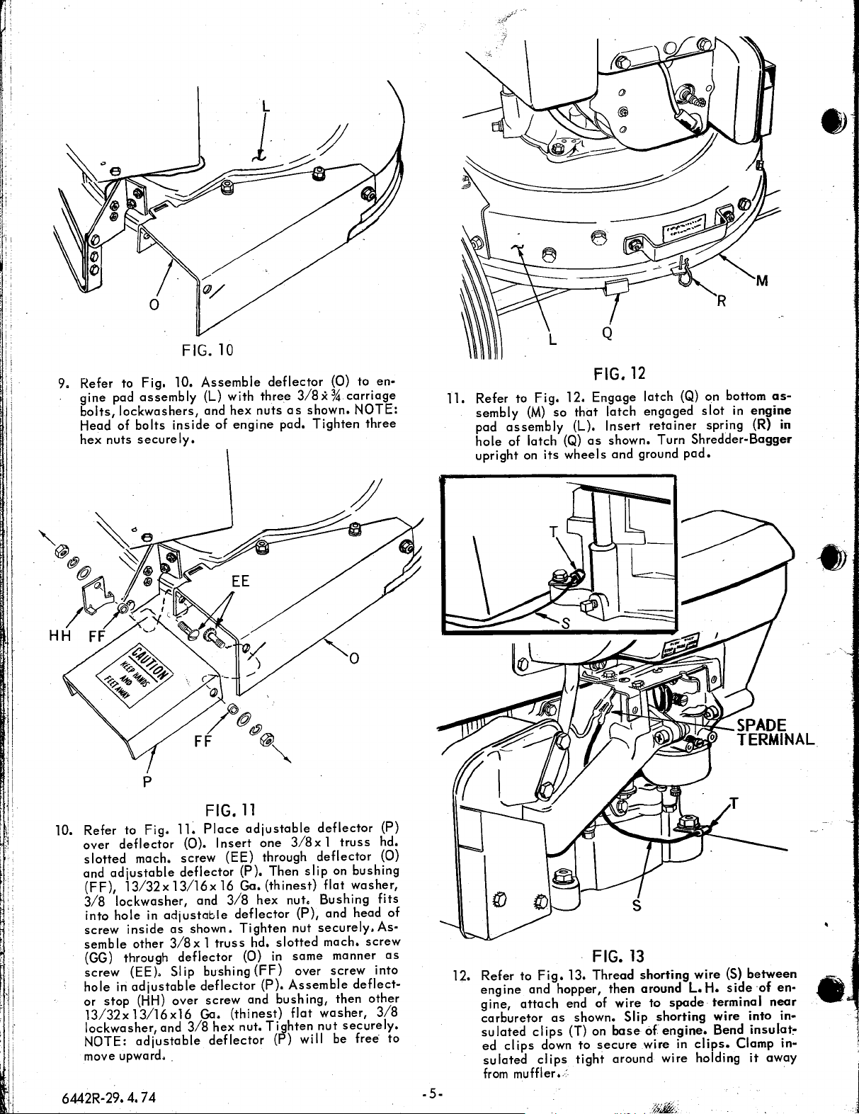
9. Refer to
gine
pad
bolts,
lockwashers,
Head of
hex
nuts
Fig.
10.
assembly
bolts
inside
securely,
FIG.
Assemble
(L) with
and
10
hex
of
three
nuts
engine
deflector
3/8.X %
as
shown.
pad.
Tighten
(0)
carriage
NOTE:
to
three
en·
11.
Refer to
sembly
pad
hole
upright on
(M)
assembly
of latch (Q)
Fig.
its
12.
so
that
(L).
wheels
FIG.
12
Engage
latch
Insert
as
shown. Turn
and
latch
engaged
retainer
ground
(Q) on bottom
slot
in
engine
spring (R) in
Shredder-Bagger
pad.
as-
10. Refer to
over
deflector
slotted
and
adjustable
(FF)
13/32x
3/8 1lockwasher,
into
hole
screw
inside
semble
(GG) through
screw
hole
or
13/32xl3/16xl6
lockwasher
NOTE:
move upward
6442R-29. 4. 7 4
other
(EE). Slip bushing
in
adjustable
stop
p
Fig.
11.
mach.
(HH)
ad(ustable
(0).
screw
deflector
13/16x
in
adjustable
as
3/8x l truss
deflector
over
and
3/8
•.
shown.
FIG.
Place
Insert
(EE) through
16 Ga.
and
3/8
deflector
Tighten
deflector
screw
Ga.
(thinest)
hex
nut.
deflector
11
adjustable
one
(P).
Then
(thinest)
hex
nut,
hd.
slotted
(0)
in
(FF)
(P).
Assemble
and
bushing,
Tighten
(P) will be
deflector
3/8x l truss
deflector
slip
on bushing
flat
washer,
Bushing
(P),
and head
nut
securely.As·
mach.
same
manner
over
screw
deflect·
flat
then
washer,
nut
securely.
free
(P)
hd.
(0)
fits
of
screw
as
into
other
3/8
to
-5-
12.
Refer to
engine
gine,
carburetor
sulated
ed
sulated
from
and hopper,
attach
clips
muffler
Fig.
as
clips
down
clips
13.
end
shown.
(T) on
•.
:
FIG.
13
Thread
of
to
tight
secure
shorting
then
around
wire
to
Slip
base
around wire holding
shorting
of
wire in
wire
L.
spade
engine.
clips.
(S)
between
H.
side
of
en·
te~min_al
wire into
Bend insulat!"
Clamp
it
n4:°r
in·
in·
away
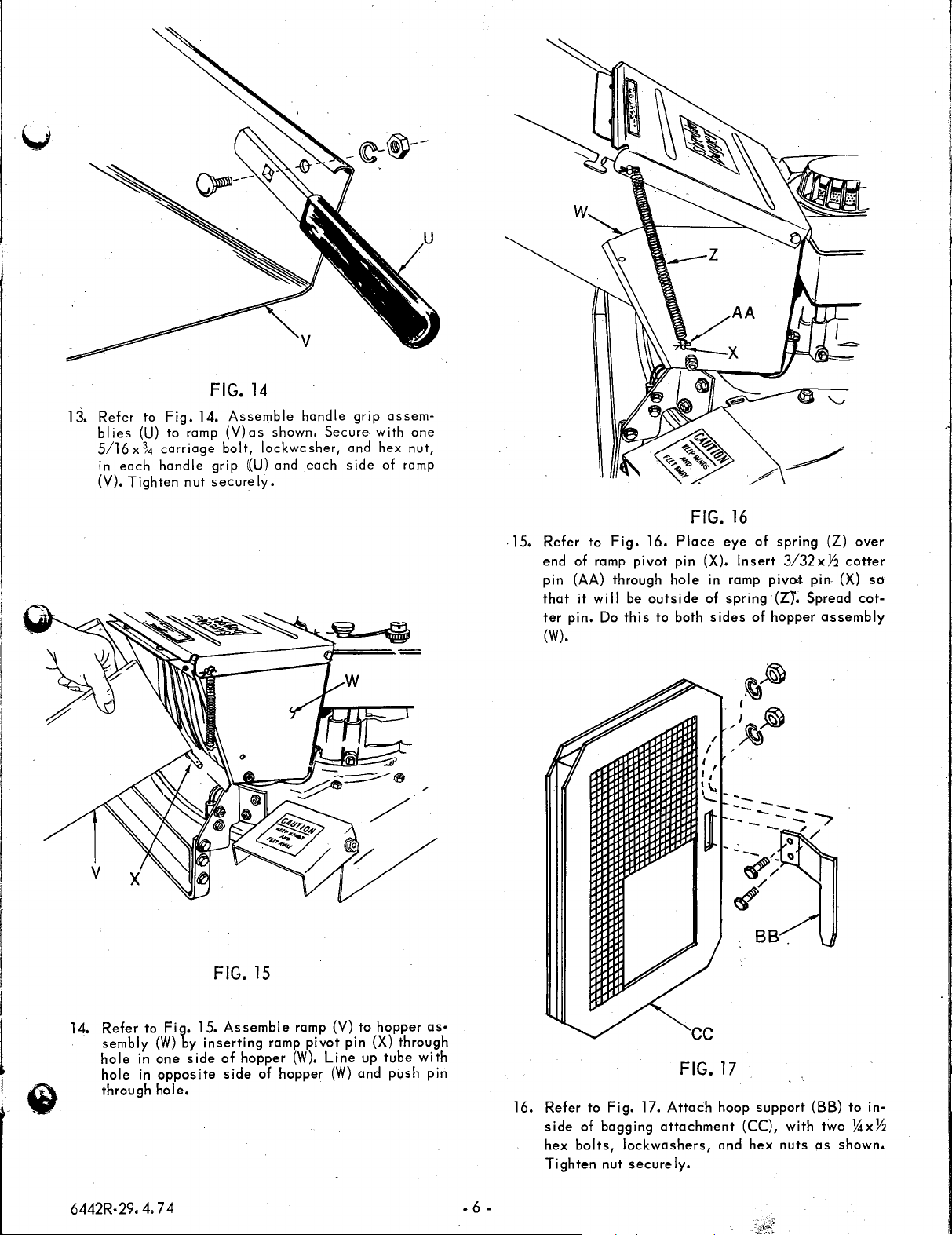
13.
Refer
blies
5/16
in
each
(V),
to
Fig.
(U)
to
x
~4
carriage
handle
Tighten
14.
ramp
nut
FIG.
14
Assemble
(V)as
bolt,
grip
((U)
securely.
handle
shown.
lockwasher,
and
Secure
each
grip
and
side
assem-
with
one
hex
nut,
of ramp
.15,
Refer
to
end
of ramp
pin (AA)
that
it
ter
pin.
(W).
Fig.
through
will
Do
pivot
be
this
16.
Place
pin (X).
hole
outside
to
both
FIG.
in ramp
of
sides
16
eye
Insert
spring
of
piveot.
of
spring
3/32xY:i
(ZY.
hopper
(Z)
pin (X)
Spread
assembly
over
cotter
so
cot-
I
I
I
14.
Refer
sembly
hole
hole
through
6442R-29.
to
Fig.
(W)
in
one
in
opposite
hole.
4. 7 4
15.
by
inserting
side
FIG.
15
Assemble
of
hopper
side
ramp
of
ramp (V)
pivot
(W).
hopper
pin (X)
Line
(W)
to
up
and
hopper
through
tube
push
as•
with
pin
- 6 -
16.
Refer
side
of
hex
bolts,
Tighten
to
Fig.
bagging
lockwashers,
nut
17.
Attach
attachment
securely.
cc
FIG.
17
hoop
and
support
(CC),
hex
with
nuts
(BB)
two
as
to
in·
!4xY2
shown.

I :
: :
~!
I
I.
DD
i1
BB
/
\
\
FIG.
18
17. Refer to
smaller
shown.
least
be
Fig.
flange
NOTE: bagging
2"
inside
outside
bag
18.
Assemble
of bagging
bag, and hoop support (BB)
as
shown.
plastic
attachment
attachment
bag (DD)
(CC)
must be
over
as
at
must
19. Refer to
embly over
support (BB) .down
enter
both
FIG.
Fig.
20. Slip bagging
adjustable
so
slots
in
deflector
20
deflector
that
hoop support
(0).
attachment
(P).
Slip hoop
{BB}
ass-
wi
11
instructions
before
operating
NEVER
IN
TERRAIN.
FOOTING
FIG.
19
18. Refer to
side
(CC).
tachment.
·:,
'.
;.:
;
i.
i
l
·11
6442R-29. 4.
of
This
Fig.
plastic
bag band
74
19.
Stretch
bag (DD) and bagging
bag band (EE)
secures
bag to bagging
over
out•
attachment
at-
- 7 -
WET
OPERATE
GRASS,
MUDDY,
ALWAYS
..
THE
SHREDDER-BAGGER
UNEVEN
BE
SURE
OR
OF
ROUGH
YOUR
 Loading...