

Page 1

MRN
MODEL NUMBER
Assembly
Operation
Customer Responsibilities
Service and Adjustments
Repair Parts
917.259573 OWNER'SMANUAL
For answers to your questions
about this product, Call:
1-800-659-5917
Sears Craftsman Help Line
5 am - 5 pro, Mort - Sat
CAUTION: Read and follow all safety rules and instructions before operating this equipment.
................................... m
Page 2

Safe Operation Practices for Ride-On Mowers
IMPORTANT: TH_S CUTTING MACHINE iS CAPABLE OF AMPUTATING HANDS AND FEET AND THROWING OBJECTS.
FAILURE TO OBSERVE THE FOLLOWING SAFETY INSTRUCTIONS COULD RESULT iN SERIOUS INJURY OR DEATH.
I. GENERAL OPERATION
. Read, understand, and follow all instructions in the manual
and on the machine before starting.
- Only allow responsible adults, who are famiiiar with the
instructions, to operate the machine.
. Clear the area of objects such as rocks, toys, wire, etc.,
which could be picked up and thrown by the blade.
• Be sure the area isclear of other people before mowing. Stop
machine if anyone enters the area.
- Never carry passengers.
• Do not mow in reverse untess absolutely necessary. AIways
look down and behind before and while backing,
= Be aware of the mower d}scharge direction and do not point
it at anyone_ Do not operate the mower without either the
entire grass catcher or the guard in place.
o Slow down before turning.
= Never leave a running machine unattended. Always turn off
blades, set parking brake, stop engine, and remove keys
before dismounting.
• Turn off blades when not mowing.
o Stop engine before removing grass catcher or unc!ogging
chute.
. Mow only in daylight or good artificial tight,
• Do not operate the machine white under the influence of
alcohol or drugs.
• Watch for traffic when operating near or crossing roadways,
• Use extra care when loading or unloading the machine into
a trailer or truck.
I1o SLOPE OPERATION
Slopes are a major factor related to loss-of-control and
tipover accidents, which can result in severe injury or
death. Alt slopes require extra caution. If you cannot back
up the slope or if you feel uneasy on it, do not mow it.
DO:
= Mow up and down slopes, not across.
• Remove obstacles such as rocks, tree limbs, etc.
= Watch for holes, ruts, or bumps. Uneven terrain could
ovedurn the machine. Tati grass can hide obstacles.
• Use slow speed. Choose a low gear so that you will not have
to stop or shift whi_e on the slope.
. Follow the manufacturer's recommendations for wheel
weights or counterweights to improve stability.
• Use extra care with grass catchers or other attachments.
These can change the stability of the machine.
= Keep all movement on the slopes slow and gradual_ Do not
make sudden changes in speed or direction.
,, Avoid starting or stopping on a slope. If tires lose traction,
disengage the blades and proceed slowly straight down the
slope.
DO NOT,"
• Do not turn on slopes untess necessary, and then, turn slowly
and graduaJ_y downhill, if possible.
• Do not mow near drop-oils, ditches, or embankments. The
mower could suddenly turn over if a wheel is over the edge
of a cliff or ditch, or if an edge caves in.
° Do not mow on wet grass. Reduced traction could cause
sliding.
• Do not try to stabilize the machine by putting your foot on the
ground.
Do not use grass catcher on steep slopes.
SAFETY RULES
III. CHILDREN
Tragic accidents can occur if the operator is not alert to the
presence of children. Children are often attracted to the
machine and the mowing activity. Never assume that
children will remain where you last saw them.
. Keep children out of the mowing area and under the watchful
care of another responsible adult.
• Be alert and turn machine off if children enter the area.
• Before and when backing, look behind and down for small
chiJdren.
• Never carry children, They may fall off and be seriously
injured or interfere with safe machine operation.
- Never allow children to operate the machine.
° Use extra care when approaching blind corners, shrubs,
trees, or other objects that may obscure vision.
IV. SERVICE
• Use extra care in handling gasoline and other fuel& They are
flammable and vapors are explosive.
Use oniy an approved container.
Never remove gas cap or add fuel with the engine
running. Allow engine to cool before refueling. Do not
smoke.
Never refuel the machine indoors.
Never store the machine or fuel container inside where
there is an open flame, such as a water heater.
• Never run a machine inside a closed area.
• Keep nuts and bolts, especially blade attachment bolts, tight
and keep equipment in good condition.
• Never tamper with safety devices. Check their proper
operation regularly.
° Keep machine free of grass, leaves, or other debris build-up.
Clean oil or fuel spillage. Allow machine to cool before
storing.
- Stop and inspect the equipment if you strike an object.
Repair, if necessary, before restarting.
• Never make adjustments or repairs with the engine running,
, Grass catcher components are subject to wear, damage, and
deterioration, which could expose moving parts or aIIow
objects to be thrown. Frequently check components and
replace with manufacturer's recommended parts, when nec-
essary.
o Mower blades are sharp and can cut. Wrap the blade(s) or
wear gtoves, and use extra caution when servicing them.
o Check brake operation frequently. Adjust and service as
required.
The en gine exhaust from this product contains
A WARNING A
chemicals known to the State of California to
cause cancer, birth defects, or other reproduc-
tive harm.
!,,ir_L i , i n,nll nl
Page 3

CONGRATULATIONS on your purchase of a Sears
Tractor. It has been designed, engineered and manufac-
tured to give you the best possible dependability and
performance.
Should you experience any problem you cannot easily
remedy, please contact your nearest Sears Authorized
Service Center/Department Department. We have com-
petent, welFtrained technicians and the proper tools to
service or repair this tractor.
Please read and retain this manual. The instructions will
enable you to assemble and maintain your tractor properly.
Always observe the "SAFETY RULES".
NUMBER 9I 7.259573
SERIAL
NUMBER
DATE OF PURCHASE
THE MODELAND SER1ALNUMBERSWlLL BE FOUND
ON A PLATE UNDER THE SEAT.
YOU SHOULD RECORD BOTH SERIAL NUMBER AND
DATE OF PURCHASE AND KEEP IN A SAFE PLACE
FOR FUTURE REFERENCE.
MAINTENANCE AGREEMENT
A Sears Maintenance Agreement is available on this prod-
uct. Contact your nearest Sears store for details.
PRODUCT SPECIF!CATIONS
HORSEPOWER: 19.5
GASOLINE CAPACITY 3.5 GALLONS
AND TYPE: UNLEAD[:iiD RE!GULAR
OIL TYPE (API-SF/SGiSH): SAE 30 (_'.bow_32'_F)
SAE 5W-30 (below 32°F)
OIL CAPACITY: 3.0 PINTS
SPARK PLUG: CHAMPION RJ19LM
(GAP: .030")
VALVE CLEARANCE: INTAKE: .004" - .006"
EXHAUST: .007" - .009"
GROUND SPEED (MPH): FORWARD: 0 - 5.5
REVERSE: 0-2.4
TIRE PRESSURE: FRONT: t4 PSI
REAR: t0 PSi
CHARGING SYSTEM: 3 AMPS BATTERY
5 AMPS HEADLIGHTS
BATTERY: AMPiHR: 30
MIN. CCA: 240
CASE SIZE: UlR
BLADE BOLT TORQUE: 30-35 FT. LBS.
CUSTOMER RESPONSIB L TIES
Read and observe the safety rules.
o Foltow a regular schedule in maintaining, caring for and
using your tractor.
* Follow the instructions under "Customer Responsibili-
ties" and "Storage" sections of this owner's manual.
WARNING: This tractor is equipped with an internal
combustion engine and should not be used on or near any
unimproved forest-covered, brush-covered or grass-cov-
ered land unless the engine's exhaust system is equipped
with a spark arrester meeting applicable local or state laws
(if any). Ifa spark arrester is used, it should be maintained
in effective working order by the operator.
In the state of California the above is required by law
(Section 4442 of the California Pubtic Resources Code).
Other states may have similar laws. Federal laws apply on
federal lands. A spark arrester for the muffle_ is available
through your nearest Sears Authorized Service Center/
Department (See REPAIR PARTS section of this manual).
MM|TED TWO YEAR WARRANTY ON CRAFTSMAN RiDiNG EQUIPMENT
For two (2) years from the date of purchase, if this Craftsman Riding Equipment is maintained, lubricated and tuned up according
to the instructions in the owner's manual, Sears will repair or replace, free of charge, any parts found to be defective in material or
workmanship.
This Warranty does not cover:
o Expendable items which become worn during normal use, such as blades, spark plugs, air cleaners, belts, etc.
Tire replacement or repair caused by punctures from outside objects, such as nails, thorns, stumps, or glass.
* Repairs necessary because of operator abuse, negligence, improper storage or accident or the failure to maintain the
equipment according to the instructions contained in the owner's manual.
* Riding equipment used for commercial or rental purposes.
LiMiTED 90 DAY WARRANTY ON BATTERY
For ninety (90) days from date ol purchase, if any battery inctuded with this riding equipment proves defective in material or
workmanship and our testing determines the battery will not hold a charge, Sears wilt replace the battery at no charge.
IN-HOME WARRANTY SERVICE ON YOUR CRAFTSMAN RIDING EQUIPMENT IS AVAILABLE AT NO-CHARGE FOR 30
DAYS FROM THE DATE OF PURCHASE PLEASE CONTACT YOUR NEAREST SERVICE CENTER. AFTER 30 DAYS FROM
THE DATE OF PURCHASE, WARRANTY SERVICE tS AVAILABLE BY TAKING YOUR CRAFTSMAN RIDING EQUIPMENT TO
YOUR NEAREST SEARS SERVICE CENTER (IN-HOME WARRANTY SERVICE WILL STILL BE AVAILABLE AFTER 30 DAYS
FROM THE DATE OF PURCHASE BUT A STANDARD TRIP CHARGE WILL APPLY.) THIS WARRANTY APPLIES ONLY
WHILE THIS PRODUCT IS IN THE UNITED STATES.
This Warranty gives you specific legai rights, and you may also have other rights which may vary from state to state.
SEARS, ROEBUCK AND CO,, D/817 WA, HOFFMAN ESTATES, IL 60179
3
Page 4

TABLE OF CONTENTS
SAFETY RULES ............................................................ 2
PRODUCT SPECIFICATIONS ...................................... 3
CUSTOMER RESPONSIBILITIES ..................... 3, 17-20
WARRANTY .................................................................. 3
TABLE OF CONTENTS ................................................ 4
INDEX ............................................................................ 4
TRACTOR ACCESSORIES .......................................... 5
ASSEMBLY .............................................................. 7-10
iNDEX
A
Accessories ............................................ 5
Adjustments:
Brake ........................................... 24
Carburetor ................................... 27
Mower:
Front-To-Back ........................ 22
Side-To-Side .......................... 22
Throttle Control Cable ............ 26-27
Air Filter, Engine ................................. 19
Air Screen, Engine ............................. 19
Assembly ......................................... 7-10
8
Battery:
Charging ..................................... 18
Cleaning ...................................... 18
Starting with Weak Battery .......... 26
Storage ....................................... 28
Terminals .................................... 18
Belts:
Motion Drive
Removal/Replacement ........... 24
Mow_r Drive
Removal/Replacement ........... 23
Mower Blade Drive
Removal/Replacement ........... 23
Blade:
Sharpening .................................. ! 8
Replacement ..................... _......... 18
Brake Adjustment ............................... 24
C
Carburetor Adjustment ....................... 27
Controls, Tractor ................................ 13
Customer Responsibilities .......... 3,17-20
Engine:
Air Filter ................................... 19
Air Screen, Engine .................. 19
Battery ..................................... 18
Cooling Fins, Engine ............... !9
Engine Oil ............................... 20
Fuel Filter ................................ 20
Spark Plugs ............................. 18
Tractor:
Blades ..................................... 18
Lubrication Chart ..................... t 7
Maintenance Schedule ........... 17
Tire Care ......................... 8,18,25
Cutting Height, Mower ........................ 13
Electrical:
Interlocks and Relays .................. 26
Schematic ................................... 31
Wiring Diagram ........................... 32
Engine:
Air Filter ....................................... 19
Air Screen .................................... 19
Cooling Fins, Engine ................... 20
Oil Change .................................. 19
Oil Level ................................. t4,19
Oil Type ....................................... 19
Preparation ................................. 14
Repair Parts ........................... 48-53
Starting ........................................ 14
Storage ....................................... 28
Filters:
Air ................................................ t 9
Fuel ............................................. 20
Fuel:
Type ............................................ 14
Storage ....................................... 28
Fuse ................................................... 26
Gauge Wheels ................................ 9,t4
Hood Removal/Installation ................. 26
Leveling Mower Deck .................... 21-22
Lubrication Chart ................................ 17
Maintenance Schedule ...................... !7
Mower:
Adjustment, Front-to-Back .......... 22
Adjustment, Side-to-Side ............ 22
Blade Sharpening ....................... 18
BJade Replacement ..................... 18
Cutting Height ............................. I3
Installation ................................ 9,21
Operation ............................... 11-!6
Removal ...................................... 21
Mowing Tips ....................................... 16
Muffler ................................................ 20
Spark Arrester .......................... 3,40
Mutcher Plate ..................................... 10
OPERATION ........................................................... t 1-18
MAINTENANCE SCHEDULE ...................................... 17
SERVICE AND ADJUSTMENTS ............................ 2t-27
STORAGE ................................................................... 28
TROUBLESHOOTING ............................................ 29-30
REPAIR PARTS - TRACTOR .................. ",.............. 32-47
REPAIR PARTS - ENGINE ..................................... 48-53
PARTS ORDERiNG/SERVICE .................. BACK PAGE
E
Oil:
Cold Weather Conditions ....... 14,t 9
Engine ....................................... :. 19
Storage ........................... :........... 28
Operation ...................................... 11-16
Operating Mower ................................ 14
Options:
Accessories ................................... 5
Spark Arrester .......................... 3,40
Parking Brake ................................ 12-13
Parts Bag ............................................. 6
Parts, Replacement/Repair ........... 32-47
Product Specifications ........................... 3
F
G
H
L
M
Repair Parts .................................. 32-47
Safety Rules ......................................... 2
Seat ...................................................... 8
Service and Adjustments .............. 21-27
Brake ........................................... 24
Carburetor ................................... 27
Fuse ............................................ 26
Hood Removal/installation .......... 26
Motion Drive Belt
Removal/Replacement ........... 24
Mower Drive
Removal/Replacement ........... 23
Mower Blade Drive Belt
Removal!Replacement ........... 23
Mower Adjustment:
Front-to-Back ......................... 22
Side-to-Side ........................... 22
Mower Installation ....................... 21
Mower Removal .......................... 2t
Tire Care ............................. 8,18,25
Slope Guide Sheet ............................. 55
Spark Ptugs ........................................ 20
Specifications ..................... :................. 3
Starting the Engine ....................... t4-t5
Steering Wheel ................................ 7,25
Stopping the Tractor ........................... !3
Storage ............................................... 28
Throttle Control Cable Adjustment ..... 26
Tires ........................................... 8, ! 8,25
TrouMe Shooting Oharl .................. 29-30
Transaxle Repair Parts ................. 46-47
O
P
R
S
T
W
Warranty ............................................... 3
Wiring Diagram .................................. 32
Wiring Schematic ............................... 31
Page 5

ACCESSO AN ATTACHMENTS
These accessories and attachments were available through most Sears retail outlets and service centers when the tractor was purchased.
Most Sears stores can order these items for you when you provide the model number of your tractor.
ENGINE MAINTENANCE
SPARK PLUG GAS CAN ENGINE OiL AiR FILTER BLADES } @ELTSFUELSTAB_L|ZER
PERFORMANCE
Sears offers awide variety of attachments that fit your tractor. Many of these are tisted below with brief explanations of how they can help
you. This listwas current at the time ofpublication; however, itmay change in future years ° more attachments may be added changes
may De made in these attachments, or some may no _onger be available or fit your model. Contact your nearest Sears store for the
accessories and attachments that are available for your tractor,
Most of these attachments do not require additional hitches or conversion kits (these that de are indicated) and are designed for easy
attaclting and detaching,
AERATOR promotes deep root growth for a healthy lawn. Ta-
pered 2,5-inch steel spikes mounted on t0-inch diameter discs
puncture holes in soil at close intervals to let moisture soak in.
SteeJ weight tray for increased penetration.
BAGGER lets you collect grass clippings and leaves for a
healthier, neater looking lawn. Two Permanex containers hold
30-ga!ion plastic bags_
BUMPER protects front end of tractor from damage.
CARTS make hauling easy. Variety of sizes available, plus
accessories such as side panei kits, toot caddy, cart cover,
protective mat and dolly.
CORING AERATOR takes small plugs out of soil to a_fow mois-
ture and nutrients to reach grass roots. 364nch swath. 24
hardened steel coring tips. t50 lb. capacity weight tray.
EASY OIL DRAIN VALVE makes oit changes easier, faster.
FRONT NOSE ROLLER canters in front of mower deck to reduce
chances of "scalping" on uneven terrain.
GANG HITCH Jetsyou tow 2 or 3 pull-behind attachments at once.
such as sweepers, dethatchers, aerators (not for use with rollers,
carts or other heavy attachments),
GAUGE WHEELS on both sides of the mower deck reduce
chances of "scalping" on uneven terrain. For mower decks not so
equipped.
MULCH RAKE./DETHATCHER loosens soil and flips thatch and
matted leaves to lawn surface for easy pickup. Twenty spring tine
teeth. UsefiJltopreparebareareasforseeding. Available for front
or rear mounting. HIGH PERFORMANCE REEL-ACTION
SPRING TINE DETHATCHER covers 36-inch wide path and
tosses thatch into large hopper. Mounts behind tractor.
MULCHING CLOSE-OUT PLATE KIT, once installed, lets you
mulch, discharg e or bag clippings (bagger optional) without
changing btades. For models not equipped as 3-in-1 Convertible
mowers. See "MOWER" in the Repair Parts section of this
manuat,
RAMP TOPS AND FEET let you load and unload tractor from a
pickup truck, Use with 2 x 8 or 2 x 101umber,
ROLLER for smoother lawn surface. 36-inch wide, 18-inch
diameterwater-tight drum holds upto 390 lbs, ofweight, Rounded
edges prevent harm to tuff. Adjustable scraper automatically
cleans drum.
SNOW BLADE forsnow removal oniy. 14-inch high, 48-inch wide
bladeclears 42-inch path when angled left or dght, Raises, towers
with side lever. Adjustable skids; replaceable, reversible scraper
bar+ (Use with tire chains and wheel weights and/or rear drawbar
weight.)
SNOWTHROWER has 40-inch swath, Drum-type auger handles
powdery and wet/heavy snow, Mounts easily with simple pin
arrangement. Discharge chute adjusts from tractor seat. 6-inch
diameter spout discharges snow 10 to 50 feel Lift controiied at
tractor seat, (Use with chains and wheel weights and/or rear
drawbar weight,)
SPRAYERS use 12-voft DC electric motor that connects to the
tractor battery or ether 12-volt source, includes booms for
automatic spraying and hand held wand for spot spraying, Wand
has adjustable spray pattern. For applying herbicides, insecti-
cides, fungicides and liquid fertilizers.
SPREADER/SEEDERS make seeding, fertilizing, and weed kill-
ing easy. Broadcast spreaders are also useful for granular de-
icers and sand,
SWEEPERS let you collect grass clippings and leaves,
TILLER has 5 hp engine and 364nch swath to prepare seed beds,
cultivate and compost garden residue. Tiller has its own built-in
lift and depth control system and does NOT require a sleeve hitch.
Fits anytawn, yard or gardentractor. Simplyhookuptothetractor
drawbar and go! Optional accessories convert unit for
dethatching, aerating, hilling...without tools.
TIRE CHAINS are heavy duty; closely spaced extra-large cross
links give smooth ride, outstanding traction.
TRACTOR CAB has heavy duty vinyl fabric over tubular steel
frame, ABS plastic top; dear plastic windshield offers 360 degree
visibility. Hinged metaf doors with catch_ Keeps operator warm
and dry. Remove vinyf sides and windshields for use as sun
protector in summer. Optional accessories include: tinted/
tempered solid safety glass windshield with hand operated wiper;
12-volt amber caution light for mounting on cab top.
VACS for powerful collection of heavy grass clippings and leaves,
Optionat wand attachment to pick up debris in hard-to-reach
places. VAC/OHIPPER includes a chipper-shredder.
WEIGHT 8RACKET for drawbar for Snow removal applications.
Uses (1) 55 lb. weight.
WHEEL WEIGHTS for rear wheels provide needed traction for
snow removal or dozing heavy materials.
Page 6

CONTENTS OF HAR[:)WA PACK
Parts Bag contents shown ful! size
(1) Large Fiat Washer (l) Hex Bolt _
\
)
'_ ji(1) Lockwasher 3/8
_ (1) Locknut
5/16-18_qX1\/f f _
(1)HexBolt _._/
5/16-18 x 1-1/4
(1) Shoulder (t) Hex Bolt 1/2-13 x 1
Bolt 5/16-18
(1) Washer
17/32 x
1-3/16.x 12
Gauge
Parts packed separately in carton
Seat
Video
Cassette
Steering
Wheel
Steering ,
Boot
Manual
Parts bag contents not shown full size
Mulcher
Plate
I
E
E
Lock
Washer 1/2
(2) Lock
O _s #10 x 5/8
Washers #10
(2) Weld 3/16 x 3/4
Nuts #t0 x 16 Gauge
(2) Hex Bolts I/4-20 x 3/4
mT]__]_ f,41_,\(2) Hex Nuts
(2) Washer Washers t/4
9/32 x 5/8 x 16 Gauge
s_ (2) Lock
(2) Washers i
(2) Shoulder
Bolts
(2) Center-
_lock Nuts .
Slope Sheet
(2) Washers 3/8
x 7/8 x t 4 Gauge
(2) Gauge
/
Wheels
2
Steering Wheel
Adapter
Steering
Wheel
Insert
Steering '_<
(2) Keys Shaft
Extension
o_
Page 7
ASSEMBLY
Your new tractor has been assembled at the factory with exception of those parts left unassembled for shipping purposes.
To ensure safe and proper operation of your tractor all parts and hardware you assemble must be tightened securely. Use
the correct tools as necessary to insure proper tightness.
TOOLS REQUIRED FOR ASSEMBLY
A socket wrench set will make assembiy easier, Standard
wrench sizes are listed,
(1) 9/16" wrench
(2) 7/16" wrenches
(2) 1/2" wrench
(1) 3/4" wrench
When right or left hand is mentioned in this manual, it
means when you are in the operating position (seated
behind the steering wheel).
TO REMOVE TRACTOR FROM CARTON
(1) 3/4" Socket w/drive rachet
Phillips Screwdriver
Tire pressure gauge
Utility knife
Pliers
STEERING
WHEEL
UNPACK CARTON
* Remove all accessible loose parts and parts cartons
from carton (See page 6).
o Cut, from top to bottom, along lines on al! four corners
of carton, and lay panels flat.
Check for any additional loose parts or cartons and
remove.
BEFORE ROLLING TRACTOR OFF SKiD
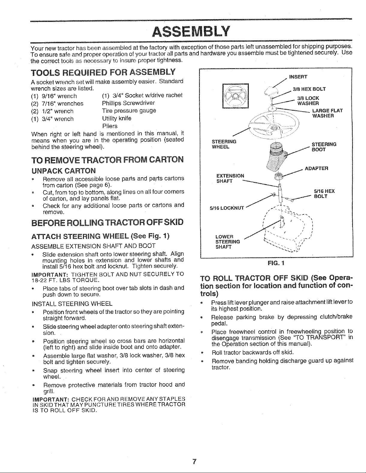
ATTACH STEERING WHEEL (See Fig. 1)
ASSEMBLE EXTENSION SHAFT AND BOOT
• Slide extension shaft onto tower steering shaft. Align
mounting holes in extension and lower shafts and
install 5/16 hex bolt and IocknuL Tighten securely.
iMPORTANT: TIGHTEN BOLT AND NUT SECURELY TO
18-22 FT. LBS TORQUE.
= Place tabs of steering boot over tab slots in dash and
push down to secure.
INSTALL STEERING WHEEL
• Position front wheels of the tractor so they are pointing
straight forward.
S_idesteering wheel adapter onto steering shaft exten-
sion.
Position steering wheel so cross barn are horizontal
(left to right) and slide inside boot and onto adapter.
• Assemble large fiat washer, 3/8 lock washer, 3/8 hex
bolt and tighten securely.
- Snap steering wheel insert into center of steering
wheet.
Remove protective materials from tractor hood and
grill.
IMPORTANT: CHECK FOR AND REMOVE ANY STAPLES
tN SKID THAT MAY PUNCTURE TIRES WHERE TRACTOR
IS TO ROLL OFF SKID.
EXTENSION
SHAFT
5/16 HEX
BOLT
FIG. 1
TO ROLL TRACTOR OFF SKiD (See Opera-
tion section for location and function of con-
trois)
Press tift lever plunger and raise attachment liftlever to
its highest position.
* Release parking brake by depressing clutch/brake
pedal.
Place freewheel control in freewheeling position to
disengage transmission (See "TO TRANSPORT" in
the Operation section of this manual).
, Roll tractor backwards off skid.
, Remove banding holding discharge guard up against
tractor.
Page 8
ASSEMBLY
HOW TO SET UP YOUR TRACTOR iNSTALL SEAT (See Fig, 3)
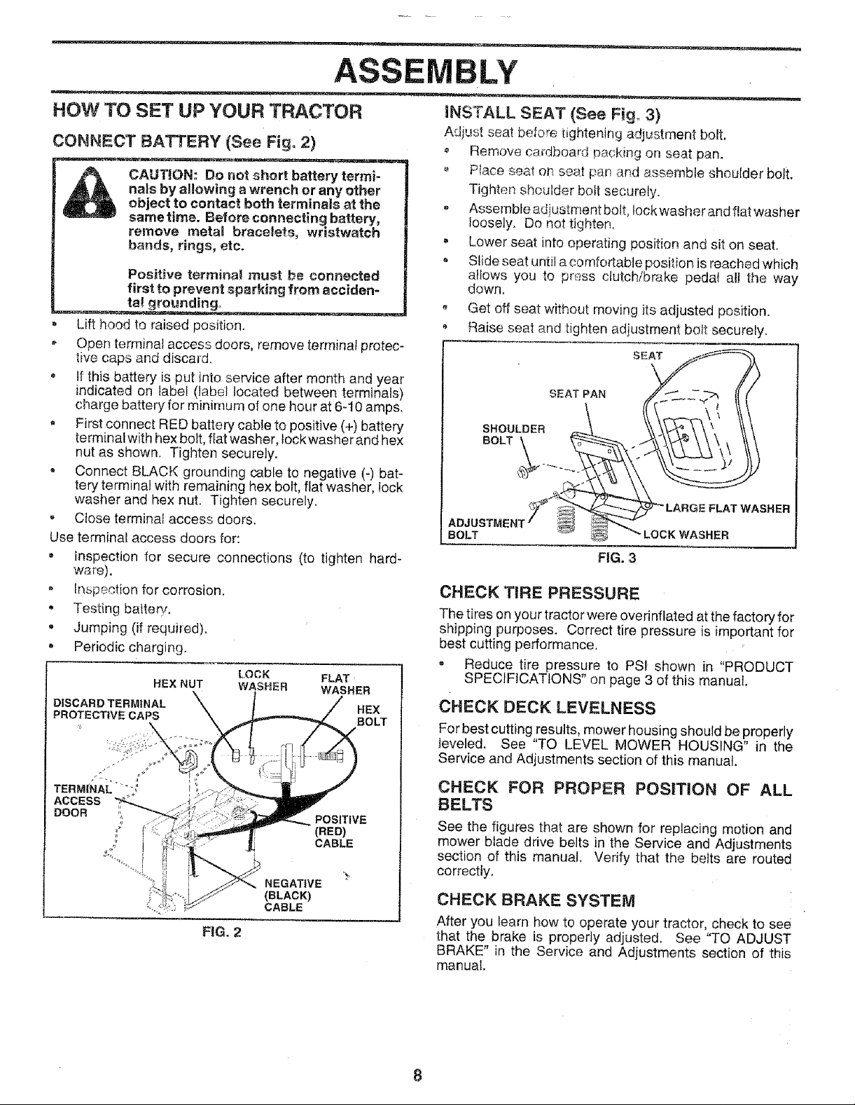
CONNECT BATTERY (See Fig, 2)
CAUTION: Do m_otshort battery termi-
nals by allowing a wrench or any other
object to contact both terminals at the
sametime. Before connecting battery,
remove metat bracelets, wristwatch
bonds, rings, etc.
Positive termina! must be connected
first to prevent sparking from acciden-
ta_ grot_nding,
Lift hood to raised position.
• Open terminal access doors, remove terminal protec-
tive caps and discard.
• It this battery is put into service after month and year
indicated on label (label located between terminals)
charge battery for minimum of one hour at 6-10 amps.
, First connect RED battery cable to positive (+) battery
terminal with hex bolt, fiat washer, lock washer and hex
nut as shown. Tighten securely.
• Connect BLACK grounding cable to negative (-) bat-
tery terminal with remaining hex bolt, flat washer, lock
washer and hex nut. Tighten securely.
• Close terminal access doors.
Use terminal access doors for:
a inspection for secure connections (to tighten hard-
wa re),
, Inspection for corrosion.
• Testing batterv_
• Jumping (if required).
° Periodic charging.
LOCK FLAT
HEX NUT WASHER WASHER
DISCARD TERMINAL HEX
PROTECTIVE CAPS BOLT
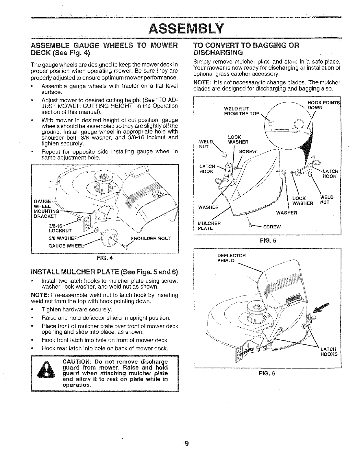
Adjust seat before tightening adjustment bolt.
Remove cardboard packing on seat pan.
Place seat o_ seat pan and assemble shoulder bolt.
Tighten shoulder bolt securely.
, Assemble aditJstment bolt, lock washer and fiat washer
loosely. Do not tighten.
= Lower seat into operating position and sit on seat.
Slide seat until a comfortable position is reached which
allows you to press clutch/brake pedal al! the way
down.
- Get off seat without moving its adjusted position.
, Raise seat and tighten adjustment bolt securely.
SEAT
SEAT PAN
SHOULDER
BOLT___
BOLT
FIG. 3
CHECK TIRE PRESSURE
The tires on your tractor were overinflated at the factory for
shipping purposes. Correct tire pressure is important for
best cutting performance.
= Reduce tire pressure to PS_ shown in "PRODUCT
SPECIFICATIONS' on page 3 of this manual.
CHECK DECK LEVELNESS
For best cutting results, mower housing should be properly
leveled. See "TO LEVEL MOWER HOUSING" in the
Service and Adjustments section of this manual.
FLAT WASHER
LOCK WASHER
FIG. 2
NEGATIVE
(BLACK)
CABLE
POSITIVE
(RED)
CABLE
CHECK FOR PROPER POSITION OF ALL
BELTS
See the figures that are shown for replacing motion and
mower blade drive belts in the Service and Adjustments
section of this manual. Verify that the belts are routed
correctly.
CHECK BRAKE SYSTEM
After you learn how to operate your tractor, check to see
that the brake is properly adjusted. See "TO ADJUST
BRAKE" in the Service and Adjustments section of this
manual.
Page 9
ASSEMBLY
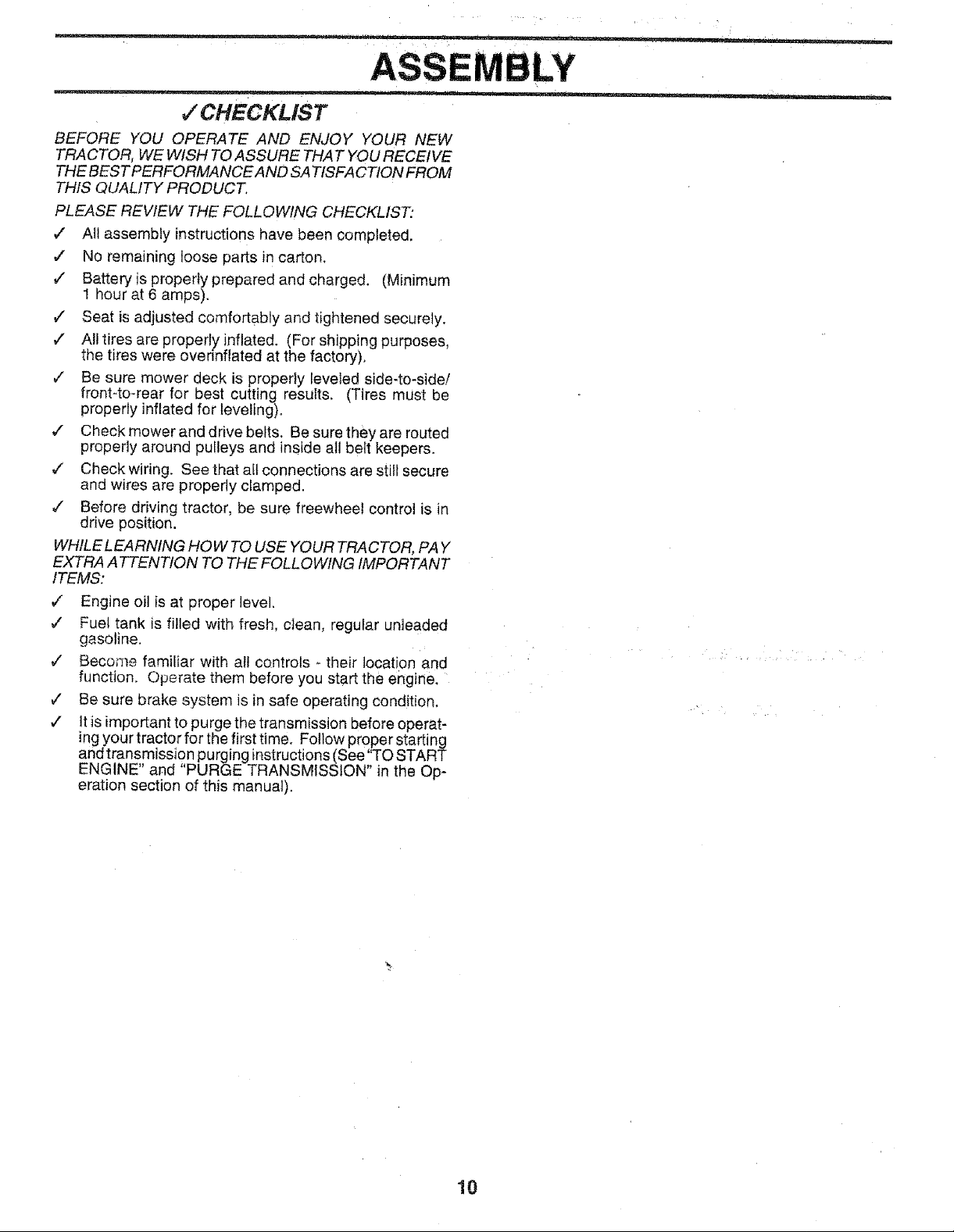
ASSEMBLE GAUGE WHEELS TO MOWER
DECK (See Fig. 4)
The gauge wheels are designed to keep the mower deck in
proper position when operating mower. Be sure they are
properly adjusted to ensure optimum mower performance.
, Assemble gauge wheels with tractor on a flat level
surface.
- Adjust mower to desired cutting height (See "TO AD-
JUST MOWER CUTTING HEIGHT" in the Operation
section of this manual).
- With mower in desired height of cut position, gauge
wheels should be assembled sothey are slightly off the
ground. Instatl gauge wheel in appropriate hole with
shoulder bolt, 3/8 washer, and 3/8-16 Iocknut and
tighten securely.
= Repeat for opposite side installing gauge wheel in
same adjustment hole.
WHEEL
BRACKET
LOCKNUT
TO CONVERT TO BAGGtNG OR
DISCHARGING
Simply remove mutcher plate and store in a safe place,
Your mower is now ready for discharging or ]nstalration of
optional grass catcher accessory.
NOTE: It is not necessary to change blades. The mulcher
blades are designed for discharging and bagging also.
HOOK POINT
WELD NUT
DOWN
\
WELD. WASHER
NUT _
LATCH "_
HOOK
WASHER
MULCHER
PLATE
LOCK
LOCK
WASHER
HOOK
WELD
NUT
GAUGE WHEEL
FiG. 4
INSTALL MULCHER PLATE (See Figs. 5 and 6)
• Install two latch hooks to mutcher plate using screw,
washer, lock washer, and weld nut as shown.
NOTE: Pre-assemble weld nut to latch hook by inserting
weld nut from the top with hook pointing down.
• Tighten hardware securely.
Raise and hold deflector shield in upright position.
• Place front of mutcher plate over front of mower deck
opening and slide into place, as shown.
, Hook front latch into hole on front of mower deck.
= Hook rear latch into hole on back of mower deck.
guard from mower. Raise and hold
CAUTION: Do not remove discharge
guard when attaching mutcher plate
and altow it to rest on plate while in
operation.
FiG. 5
DEFLECTOR
SHIELD
HOOKS
FiG. 6
9
Page 10
,/ CHECKLIST
BEFORE YOU OPERATE AND ENJOY YOUR NEW
TRACTOR, WE WISH TO ASSURE THAT YOU RECEIVE
THE BEST PERFORMANCE AND SA TISFA CTION FROM
THIS QUALITY PRODUCT.
PLEASE REVIEW THE FOLLOWING CHECKLIST:
•/ All assembly instructions have been completed.
,/ No remaining toase parts in carton.
¢" Battery'is properly prepared and charged. (Minimum
1 hour at 6 amps).
¢" Seat is adjusted comfortably and tightened securely.
,/ All tires are properly inflated. (For shipping purposes,
the tires were overinflated at the factory).
,/ Be sure mower deck is properly leveIed side-to-side!
front-to-rear for best cutting results. (Tires must be
properly inflated for leveling).
v" Check mower and drive belts. Be sure they are routed
properly around pulleys and inside all belt keepers.
¢' Check wiring. See that all connections are still secure
and wires are properly clamped.
•/ Before driving tractor, be sure freewheel control is in
drive position.
WHILE LEARNING HOW TO USE YOUR TRAC TOt l, PAY
EXTRA ATTENTION TO THE FOLLOWING IMPORTANT
ITEMS:
J Engine oil is at proper level.
¢" Fuel tank is filled with fresh, clean, regular unleaded
gasoline.
¢ Become familiar with all controls - their location and
function. Operate them before you start the engine,
¢ Be sure brake system is in safe operating condition,
¢ It is important to purge the transmission before operat-
ing your tractor for the first time. Follow proper starting
and transmission purging instructions (See "TO START
ENGINE" and "PURGE TRANSMtSSLON" in the Op-
eration section of this manual).
10
Page 11
OPERATiO
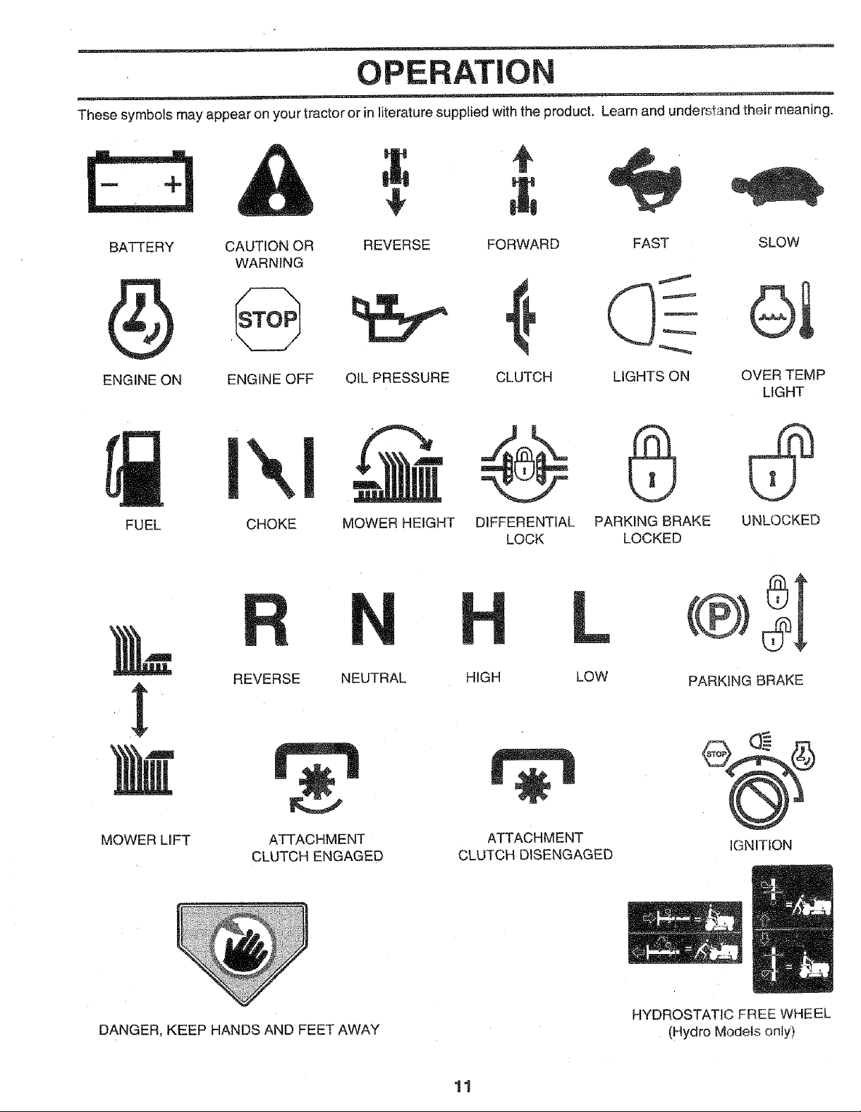
These symbols may appear on your tractor or in literature supplied with the product. Learn and understand their meaning.
BATTERY CAUTION OR REVERSE FORWARD FAST SLOW
WARNING
ENGINE ON ENGINE OFF OIL PRESSURE CLUTCH LIGHTS ON OVER TEMP
LIGHT
p-@ @
FUEL CHOKE
MOWER LIFT
MOWER HEIGHT DIFFERENTIAL PARKING BRAKE UNLOCKED
REVERSE NEUTRAL
ATTACHMENT
CLUTCH ENGAGED
LOCK LOCKED
L
HIGH LOW
ATTACHMENT
CLUTCH DISENGAGED
PARKING BRAKE
IGNITION
DANGER, KEEP HANDS AND FEET AWAY
HYDROSTATIC FREE WHEEL
(Hydro Models only)
11
Page 12
OPERATIC
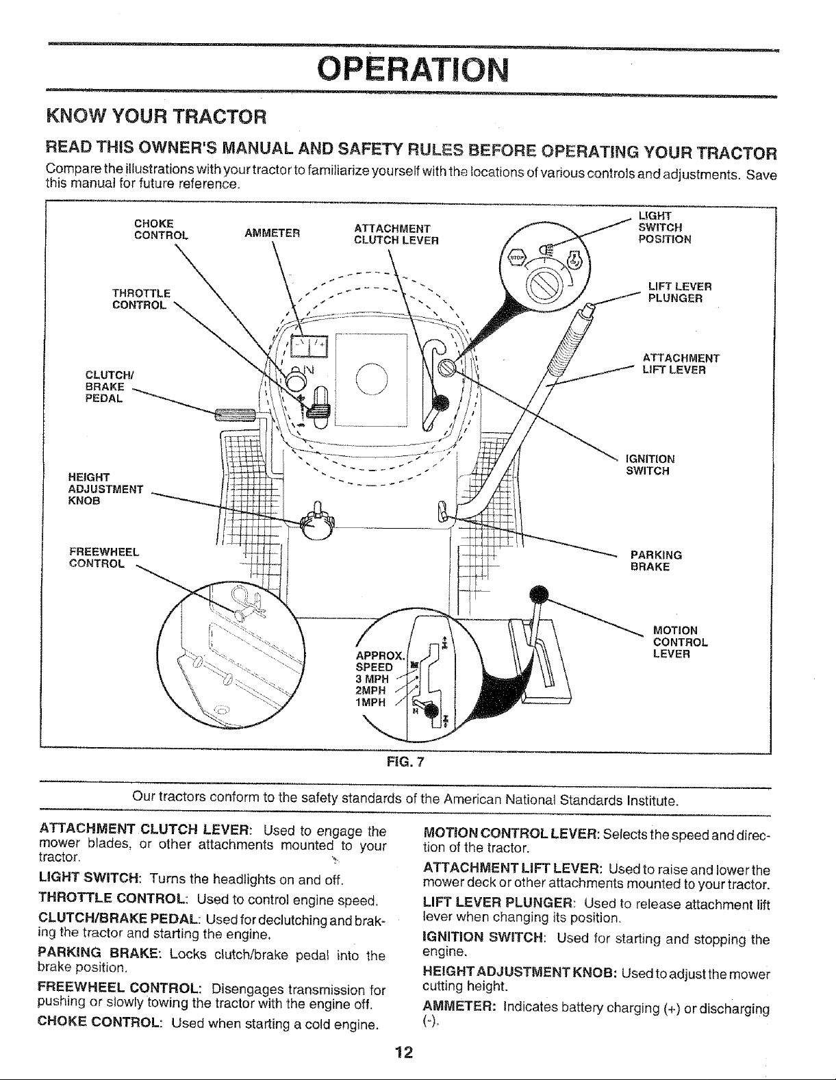
KNOW YOUR TRACTOR
READ THiS OWNER'S MANUAL AND SAFETY RULES BEFORE OPERATING YOUR TRACTOR
Compare theitlustrationswithyourtractortofami]iadzeyourselfwiththe locations of various cQntrolsand adjustments, Save
this manual for future reference.
LIGHT
CHOKE ATTACHMENT SWITCH
CONTROL AMMETER CLUTCH LEVER POSITION
THROTTLE
CONTROL
ATTACHMENT
CLUTCH/
BRAKE
PEDAL
HEIGHT
ADJUSTMENT
KNOB
LIFT LEVER
IGNITION
SWITCH
FREEWHEEL
CONTROL
APPROX.
SPEED
3MPH
2MPH
1MPH
Our tractors conform to the safety standards of the American National Standards Institute.
ATTACHMENT CLUTCH LEVER: Used to engage the
mower blades, or other attachments mounted to your
tractor. ,-.
LIGHT SWITCH: Turns the headlights on and off.
THROTTLE CONTROL: Used to control engine speed,
CLUTCHtBRAKE PEDAL: Used for dectutching and brak-
ing the tractor and starting the engine.
PARKING BRAKE: Locks clutch/brake pedat into the
brake position.
FREEWHEEL CONTROL: Disengages transmission for
pushing or slowly towing the tractor with the engine off.
CHOKE CONTROL: Used when starting a cold engine.
PARKING
BRAKE
MOTION
CONTROL
LEVER
FIG. 7
MOTION CONTROL LEVER: Selects the speed and direc-
tion of the tractor.
ATTACHMENT LIFT LEVER: Used to raise and lower the
mower deck or other attachments mounted to your tractor.
LIFT LEVER PLUNGER: Used to release attachment lift
lever when changing its position.
iGNITiON SW_TCH: Used for starting and stopping the
engine.
HEIGHTADJUSTMENT KNOB: Usedto adjustthe mower
cutting height.
AMMETER: indicates battery charging (+) or discharging
(4.
12
Page 13

OPERATION
spectacles or standard safety glasseso
HOW TO USE YOUR TRACTOR
TO SET PARKING BRAKE (See Fig. 8)
Your tractor isequipped with an operator presence sensing
switch. When engine is running, any attempt by the
operator to leave the seat without first setting the parking
brake will shut off the engine.
, Depress clutch/brake pedal into full "BRAKE" position
and held.
* Place parking brake lever in "ENGAGED" position and
releasepressurefromclutch/brakepedaL Pedal should
remain in "BRAKE" position. Make sure parking brake
wil! hold tractor secure.
THROTTLE ATTACHMENT CLUTCH
CONTROL LEVER"ENGAGE'°;
CHOKE
CONTROL
"BRAKE"
POSITION
CLUTCH_RAKE
PEDAL"DRWE .... DISENGAGED"
POSITION HEIGHT POS_ION
ADJUSTMENT
KNOB
STOPPING (See Fig. 8)
MOWER BLADES -
o Move attachment clutch Lever to "DISENGAGED"
position.
GROUND DRIVE -
- Depress dutch/brake pedal into full "BRAKE" position.
= Move motion control {ever to neutral (N) position.
IMPORTANT: THE MOTION CONTROL LEVER DOES
NOT RETURN TO NEUTRAL (N) POSITtON WHEN THE
CLUTCH/BRAKE PEDAL IS DEPRESSED.
ENGINE -
o Move throttle control to stow position.
NOTE: Failure to move throttle control to stow position and
allowing engine to idle before stopping may cause engine
to "backfire".
- Turn ignition key to "OFF" position and remove key.
Always remove key when leaving tractor to prevent
unauthorized use,
Never use choke to stop engine.
POSITION
"DISENGAGE"
MOTIONCONTROL
FIG. 8
NOTE: Under certain conditions when b'actor isstanding
idle withthe e_gine running, hot engine exhaust gases may
cause "browning" ef grass. To eliminate this possibility,
always stop engine when stepping tractor on grass areas.
ompty 1
TO USE THROTTLE CONTROL (See Fig. 8}
Always operate engine at futl throttle,
Operating et_,gineat less than full throttle reduces the
battery cha_ging rate.
- Full throttle offers the best bagging and mower perfor-
mance,
TO USE CHOKE CONTROL (See Fig. 8)
Use choke control whenever you are starting a cold engine.
Do not use to start a warm engine.
, To engage choke control, pull knob out. Slowly push
knob in to disengage.
TO MOVE FORWARD AND BACKWARD (See
Fig, 8)
The direction and speed of movement is controlled by the
motion control lever.
o Start tractor with motion control fever in neutral (N)
position,
, Release parking brake and clutch!brake pedal.
Slowly move motion control lever to desired position,
TO ADJUST MOWER CUTTING HEIGHT
(See Fig. 8)
The cutting height isc0ntrolied by turning the height adjust-
ment knob in desired direction.
• Turn knob clockwise (/_) to raise cutting height.
• Turn knob counterclockwise (_#_'_)to lower cutting
height.
The cutting height range is approximately 1-!/2" to 4". The
heights are measured from the ground to the blade tip with
the engine not running. These heights are approximate
and may vary depending upon soil conditions, height of
grass and types of grass being mowed.
The average lawn should be cut to approximately 2-1/2
inches during the coo! season and to over 3 inches
during hot months. For healthier and better looking
lawns, mow often and after moderate growth,
For best cutting performance, grass over 6 inches in
height should be mowed twice. Make the first cut
relatively high; the second to desired height,
13
Page 14

0 ERATION
TO OPERATE MOWER (See Fig. 9)
Your tractor isequippedwithanoperatorpresencesensing
switch. Any attempt by the operator to leave the seat with
the engine running and the attachment clutch engaged will
shut off the engine.
• Select desired height of cut.
Lower mower with attachment lift control.
, Start mower biades by engaging attachment clutch
control
- TO STOP MOWER BLADES - disengage attachment
clutch control.
ATTACHMENT CLUTCH
LEVER"ENGAGED"
POSiTiON
POSITION
ATTACHMENT LIFT
LEVER HIGH
POSITION
TO TRANSPORT (See Fig. 10)
When pushing or towi_g your tractor, be sure to disengage
transmission by ptacing freewheel controljn freewheeling
position. Free wheel control is ]ocated al the _ear drawbar
of tractor.
- Raise at_acilmer_t lift to highest position with attach-
ment _iftcontrct.
• Pull freewheel control knob out s.nd hold in position by
inseding retainer spri_g ir_toforv,'ard hote of control rod.
, Do not push or tow tr_ctor at more than two (2) MPH.
, To reengage transmission, reverse above procedure,
NOTE: To protecl: hood fmrn damage when transporting
your tractor on atruck or atraitor, be sure hood is dosed and
secured to tractor. Use an appropriate means of tying hood
to tractor (ro_e, cord, etc_).
HEIGHT /
ADJUSTMENT DISCHARGE
KNOB GUARD
FIG. 9
TO OPERATE ON HILLS
• Choose the slowest speed before starting up or down
hills.
, Avoid stepping or changing speed on hills.
o tf slowing is necessary, move throttle control lever to
slower position.
If stopping is absolutely necessary, push clutch/brake
pedal quickly to brake position and engage parking
brake.
• Move motion control lever to neutral (N) position.
IMPORTANT.' THE MOTION CONTROL LEVE_ClDOES
NOT RETURN TO NEUTRAL (N) POSITION WH'EN THE
CLUTCH/BRAKE PEDAL IS DEPRESSED.
, To restart movement, slowly release parking brake and
clutch/brake pedal.
, Slowly move motion control lever to slowest setting.
° Make all turns slowly.
FiG, 10
BEFORE STARTING THE ENGINE
CHECK ENGSNE OIL LEVEL (See Fig. 15)
• The engine in your tractor has been shipped, from the
factory, already filled with summer weight oil.
, Check engine oil with tractor on level ground.
• Remove oil fill cap/dipstick and wipe clean, reinsert the
dipstick and screw cap tight, walt fera few seconds,
remove and read oil level. If necessary, add oit until
"FULL" mark on dipstick is reached. Do not overfill,
, For cold weather operation you should change oil for
easier starting (See "O1L VISCOSITY CHART" in the
Customer Responsibilities section of this manual).
- To change er_gi_e oil, see the Customer Responsibili-
ties section in this manual.
ADD GASOUNE
Fili fuel tank. Use fresh, clean, regular unleaded
gasoline with a minimum of 87 octane. (Use of leaded
gasoline wilt increase carbon and lead oxide deposits
and reduce valve life). Do not mix oil with gasoline.
Purchase fuel in quantities that can be used withi__30
days to assure fuel freshness.
IMPORTANT: WHEN OPERATING iN _BMPERATURES
BELOW 32°F(0°C), USE FRESH, CLEAN WINTER GRADE
GASOLINE TO HELP INSURE GOOD COLD WEATHER
STARTING.
Page 15
OPERATION
WARNING: Experience indicates that alcohol blended
fuels (called gasohot or using ethanol or methanol) can
attract moisture which leads to separation and formation of
acids during storage. Acidic gas can damage the fuel
system of an engine while in storage. To avoid engine
problems, the fuel system should be emptied before stor-
age of 30 days or longer. Drain the gas tank, start the
engine and let it run until the fuel lines and carburetor are
empty. Use fresh fuel next season. See Storage Instruc-
tions for additional information. Never use engine or
carburetor cleaner products in the fuel tank or permanent
damage may occur,
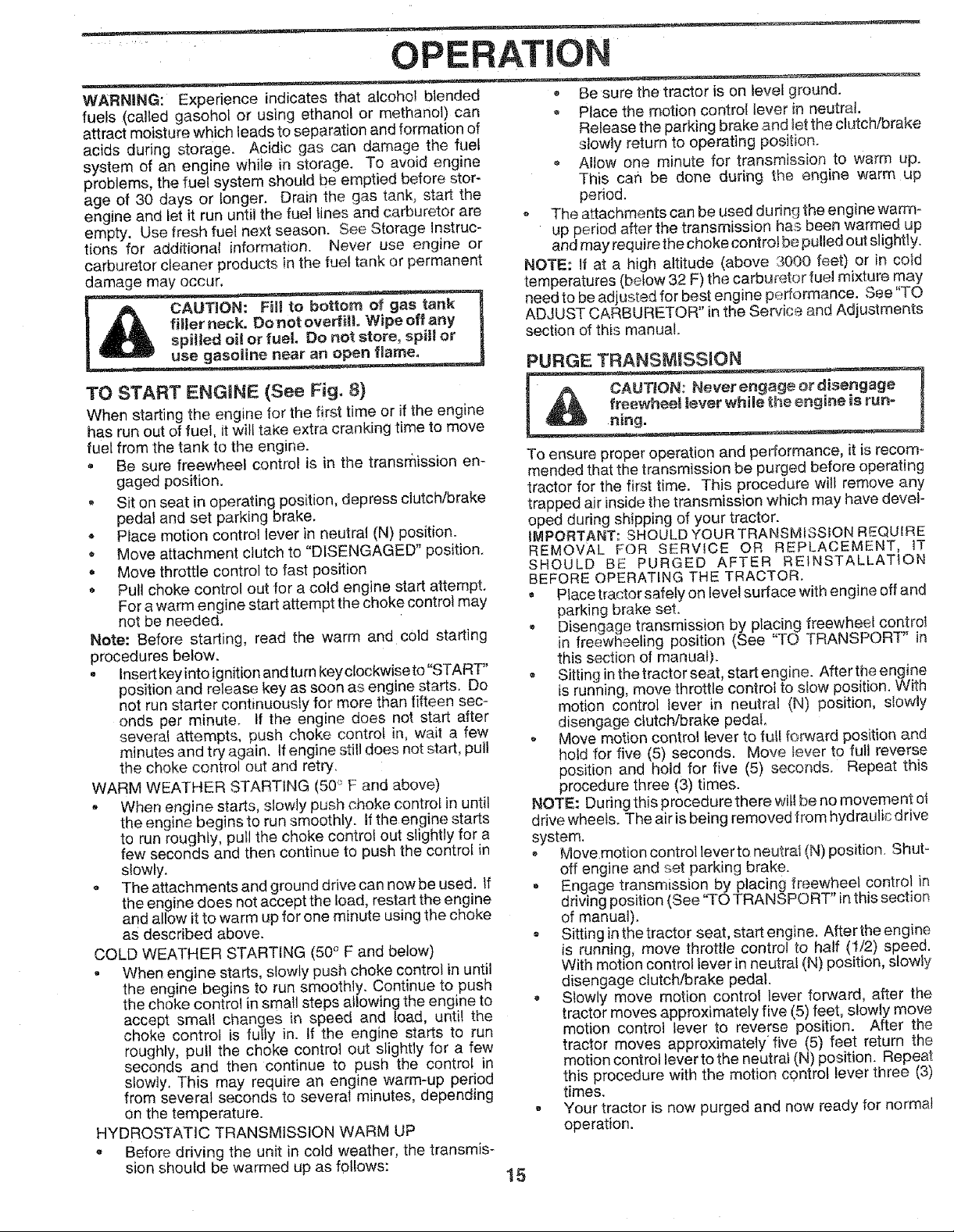
TO START ENGINE (See Fig. 8)
When starting the engine for the first time or if the engine
has run out of fuel, it will take extra cranking time to move
fuel from the tank to the engine.
• Be sure freewheel control is in the transrflission en-
gaged position.
, Sit on seat in operating position, depress clutch/brake
pedal and set parking brake.
- Place motion control lever in neutral (N) position.
• Move attachment clutch to "DISENGAGED" position,
• Move throttle control to fast position
• Pull choke control outfor a cold engine start attempt,
For a warm engine start attempt the choke control may
not be needed.
Note: Before starting, read the warm and c01d starting
procedures below.
• Insert key into ignition and turn keyctockwise to "START"
position and release key as soon as engine starts. Do
not run starter continuously for more than fifteen sec-
onds per minute. If the engine does not start after
severe! attempts, push choke contro/ in, wait a few
minutes and try again. If engine still does not start, pull
the choke control out and retry.
WARM WEATHER STARTING (50° F and above)
, When engine starts, slowly push choke control in until
the engine beginsto run smoothly, if the engine starts
to run roughly, pull the choke controi out slightly for a
few seconds and then continue to push the control in
slowly.
• The attachments and ground drive can now be used. If
the engine does not accept the toad, restart the engine
and allow it to warm up for one minute using the choke
as described above.
COLD WEATHER STARTING (50° F and below)
, When engine starts, slowly push choke control in until
the engine begins to run smoothly. Continue to push
the choke control in small steps allowing the engine to
accept small changes in speed and load, until the
choke control is fully in. If the engine starts to run
roughly, pull the choke control out slightly for a few
seconds and then continue to push the control in
slowly, This may require an engine warm-up period
from several seconds to several minutes, depending
on the temperature.
HYDROSTATIC TRANSMISSION WARM UP
• Before driving the unit in cold weather, the transmis-
sion should be warmed up as follows:
Be sure the tractor is on level ground.
Place the motion control lever Jhneutral.
Release the parking brake and Iet the clutch/brake
slowly return to operating position.
, Allow one minute for transmission to warm up.
This can be done during the engine warm up
period.
- The attachments can be used during the engine warm-
up period after the transmission has been warmed up
and may require the choke control be pulled out slightly.
NOTE: If at a high altitude (above 3000 feet) or in cold
temperatures (below 32 F) the carburetor fuel mixture may
need to be adjusted for best engine performance. See "TO
ADJUST CARBURETOR" inthe Service and Adjustments
section of this manual.
PURGE TFIANSMISSION
To ensure proper operation and performance, it is recom-
mended that the transmission be purged before operating
tractor for the first time. This procedure will remove any
trapped air inside the transmission which may have devel-
oped during shipping of your tractor.
IMPORTANT: SHOULD YOUR TRANSMISS!ON REQUIRE
REMOVAL FOR SERVICE OR REPLACEMENT, tT
SHOULD BE PURGED AFTER REtNSTALLATtON
BEFORE OPERATING THE TRACTOR.
• Place tractor safely on level surface with engine off and
parking brake set.
, Disengage transmission by placing freewheel control
in freewheeling position (See "TO TRANSPORT" in
this section of manual).
• Sitting in the tractor seat, start engine. After the engine
is running, move throttle control to slow position, With
motion control ]ever in neutral (N) position, slowly
disengage clutch/brake pedal,
, Move motion control lever to futf forward position and
hold for five (5) seconds. Move tever to full reverse
position and hold for five (5) seconds. Repeat this
procedure three (3) times.
NOTE: During this procedure there will be no movement ol
drive wheels. The air is being removed from hydraulic drive
system.
, Move motion control lever to neutrai (N) position. Shut _
off engine and set parking brake.
, Engage transmission by placing freewheel control in
driving position (See "TO TRANSPORT" in this section
of manual).
, Sitting inthetractor seat, star!engine. Aftertheengine
is running, move throttle control to half (1/2) speed.
With motion control lever in neutral (N) position, slowly
disengage clutch/brake pedal.
Slowly move motion contro! lever forward, after the
tractor moves approximately five (5) feet, slowly move
motion control lever to reverse position. After the
tractor moves approximately five (5) feet return the
motion control lever to the neutral (N) position. Repeat
this procedure with the motion control lever three (3)
times.
• Your tractor is now purged and now ready for normal
operation.
15
Page 16
OPERATION
MOWING TIPS
Tire chains cannot be used when the mower housing is
attached to tractor.
Mower should be properly leveled for best mowing
performance. See "TO LEVEL MOWER HOUSING" in
the Service and Adjustments section of this manual.
The left hand side of mower should be used for trim-
ming.
o Drive so that clippings are discharged onto the area
that has been cut. Have the cut area to the dght of the
tractor. "['his will result in a more even distribution of
clippings and mere uniform cutting.
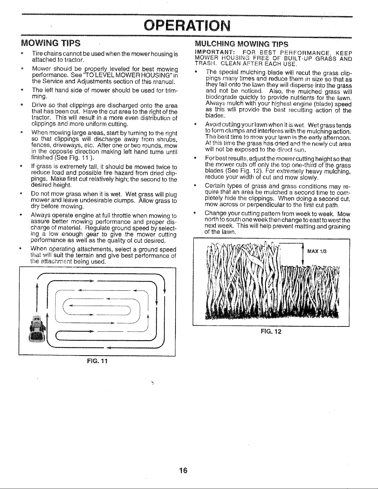
- When mowing large areas, start by turning to the right
so that clippings wilt discharge away from shrubs,
fences, driveways, etc. After one or two rounds, mow
in the opposite direction making left hand turns until
finished (See Fig. 11 ).
- If grass is extremely tall, it should be mowed twice to
reduce load and possible fire hazard from dried clip_
pings. Make first cut relatively high; the second to the
desired height.
, Do not mow grass when it is wet. Wet grass will plug
mower and leave undesirable clumps. Atlow grass to
dry before mowing.
, Atways operate engine at full throttle when mowing to
assure better mowing performance and proper dis-
charge of material, Regulate ground speed by select-
ing a low enough gear to give the mower cutting
performance as well as the quality of cut desired.
, When operating attachments, select a ground speed
that ,_vi!tsuit the terrain and give best performance of
the attachm;_nt being used.
MULCHING MOWING TIPS
IMPORTANT: FOR BEST PERFORMANCE, KEEP
MOWER HOUSING FREE OF BUILT-UP GRASS AND
TRASH. CLEAN AFTER EACH USE,
* The special mulching blade wiif recut the grass clip-
pings many times and reduce them in size so that as
they fall onto the lawn they will disperse into the grass
and not be noticed. Also, the mulched grass wilt
biodegrade quickly to provide nutrients for the lawn.
Always mulch with your highest engine (blade) speed
as this wilt provide the best recutting action of the
btades.
, Avoid cutting your lawn when it iswet. Wet grass tends
to form ck._mpsand interferes with the mulching action.
The best time to mow your law# i£the early afternoon.
At this time the grass has dried ar,d the new_y cut area
will not be exposed to the direct sun.
For best resutts, adjustthe mowercutting height so that
the mower cuts off only the top one-third of the clrass
blades (oee Fig. 12). For extremely heavy mulching,
reduce your width of cut and mow slowly.
. Certain types of grass and grass conditions may re-
quire that an area be mulched a second time to com-
pletely hide the clippings. When doing a second cut,
mow across or perpendicular to the first cut path.
* Change your cutting pattern from week to week. Mow
north to south one week then change to east to west the
next week. This will help prevent matting and graining
of the lawn.
MAX 1/3
(
FIG. 12
FiG. 11
16
Page 17

CUSTOMER RESPONSIBILIT!
MAINTENANCE SCHEDULE
FILL [N DATES
AS YOU COMPLETE
REGULAR SERVICE
;heck Brake Operation
Check Tire Pressure
T I Check for Loose Fasteners
R I" SharpenlReptace Mower Blades
A l" Lubrication Chart
Cl.
T [ Check Battery Level/Recharge
0 I Clean Battery a_td Terminals
R [ Check Transaxle Cooling
Adjust Biade Belt(e)Tension
Adjust Motion Drive Belt{s) Tension
Check Engine Oil Lever
Change Engine Oil
F_..} Clean Air Filter
N 1 Clean Air Screen
G I inspect Muffler/Spark Arrester
I Replace Oil Filter (If equipped)
N I clean Engine Cooling Fins
El
Replace Spark Plug
Replace Air Filter Paper Cartridge
Replace Fuel Filter
I - Change more often when operating under a heavy iced or in high ambient temperatures,
2 - Service mo_a often when operating in dirty or dusty conditions-
3 - I1 equipped with oil filter, change oil every 50 hours,
4- Replaceblades more oftenwhen mowingin sandysoil
;ERVICE DATES
I
i
m
5 - Ifequippedwith adjustabtesystem,
6 *Not requiredif equippedwith maintenance4reebattery.
7- Tightenfront axlepivot bo{tto 35 ft.4bs,maximum,
Donot overtighten.
GENERAL RECOMMENDATIONS
The warranty on this tractor does not cover items that have
been subjected to operator abuse or negligence. To
receive full value from the warranty, operator must maintain
tractor as instructed in this manual.
Some adjustments will need to be made periodically to
property maintain your tractor.
All adjustments in the Service and Adjustments section of
this manual should be checked at least once each season.
Once a year you should replace the spark plug, clean
or replace air filter, and check blades and belts for
wear. A new spark ptug and clean air filter assure
proper air-fuel mixture and help your engine run better
and last longer.
BEFORE EACH USE
, Check engine oil level
= Check brake operation.
, Check tire pressure.
, Check for loose fasteners.
LUBRICAT|ON CHART
(_) SPINDLE
(_) FRONT
BEARING ZERK
0
CLUTCH
PIVOT(S)
(_) SAE 30 OR 10W30 MOTOR OIL
(_ GENERAL PURPOSE GREASE
(_ REFER TO CUSTOMER RESPONSIBILITIES "ENGINE" SECTION
iMPORTANT: DO NOT OIL OR GREASE THE PIVOT POINTS
WHICH HAVE SPECIAL NYLON BEARINGS. VISCOUS LUBRi-
CANTS WILL ATTRACT DUST AND DIRT THAT WILL SHORTEN
THE LIFE OF THE SELF-LUBRICATING BEARINGS. tF YOU
FEEL THEY MUST BE LUBRICATED, USE ONLY A DRY, POW-
17 DERED GRAPHITE TYPE LUBRICANT SPARINGLY.
•_PINDLE ZERK (_)
-FRONT WHEEL (_)
BEARING ZERK
ENGINE (_
Page 18

CUSTOME RESPONSIBILITIES
TRACTOR TO SHARPEN BLADE (See Fig. 14)
Always observe safety rules when performing any mainte-
nance.
BRAKE OPERATION
tf tractor requires more than six (6) feet stepping dts[ance
at high speed inhighest gear, then brake must be adjusted.
(See "TO ADJUST BRAKE" in the Service and Adjust-
ments section of this manual)
TIRES
, Maintain proper air pressure in all tires (See "PROD-
UCT SPECIFICATIONS" on page 3 of this manual).
o Keep tires free of gasoline, oil, or insect control chemi-
cals which can harm rubber,
• Avoid stumps, stones, deep ruts, sharp objects and
ether hazards that may cause tire damage.
NOTE: Te seat tire punctures and prevent flat tires due to
slow leaks, tire sealant may be purchased from your local
parts dealer. Tire sealant also prevents tire dry rot and
corrosion.
Care should be taken to keep the blade balanced. An
unbatanced b}ade wit} cause excessive vibration and ever]..
tuat damage to mower and engine.
• the btade can be sharpened with a file er on a grindhtg
wheet. Do not attempt to sharpen while on the mower.
Q "Tocheck blade balance, you will need a 5/8" diameter
steel bolt, pin. or acene balancer. (When us nga cone
balancer, follow the instructions supplied with bal-
ancer).
• Slide blade on to an unthreaded portion of the steeJbolt
or pin and hold the bolt or ptn parallel with the ground.
If blade is balanced, it should remain in a horizontal
position, If ekher end ot the Made moves downward,
sharpen the heavy end until the biade is balanced.
NOTE: Do not use a nail foi balancing b)ade. -[he lobes of
the center hole may appear to be centered, but are not.
CENTER HOLE
BLADE CARE
For best results mower blades must be kept sharF Re-
place bent or damaged blades.
BLADE REMOVAL (See Fig, 13)
o Raise mower to highest position to allow access to
blades.
o Remove hex bolt, lock washerand flat washer securing
blade.
• Install new or resharpened blade with trailing edge up
towards deck as shown.
Reassemble hex bolt, lock washer and flat washer in
exact order as shown.
- Tighten bolt securely (30-35 Ft. Lbs. torque),
iMPORTANT: BLADE BOLT ISGRADE 8 HEAT TREATED.
NOTE: We do not recommend sharpening blade -but ifyeu
do, be sure the blade is balanced.
BLADE
FLAT WASHER ._.%
HEX BOLT
(GRADE
MANDREL
ASSEMBLY
TRAILINGEDGE
518" BOLT
OR PiN
BLADE
FiG. !4
BATTERY
Your tractor has a battery charging system which is suffi-
cient for normal use. However, periodic charging of the
battery with an automotive charger wilf extend its life.
, Keep battery and terminals clean.
, Keep battery bolts tight.
o Keep small vent holes open.
= Recharge at 6-10 amperes for I hour.
TO CLEAN BATTERY AND TERMINALS
Corrosion and dirt on the battery and terminals can cause
the battery to "leak" power.
• Remove terminal guard.
° Disconnect BLACK battery cable first the_ RED
battery cable and remove battery from tractor.
Rinse the battery with plain water and dry.
o Clean terminals and battery cable ends with wire
brush until bright.
, Coat terminals with grease or petroleum je!ly.
Reinstall battery (See "CONNECT BATTERY" in the
Assembly section of this manual).
*A GRADE 8 HEAT TREATED BOLT CAN BE
IDENTIFIED BY SJ× LINES ON THE BOLT HEAD.
FIG. 13
18
Page 19

CUSTO BILITIES
V-BELTS
Check V-belts for deterioration and wear after 100 hours of
operation and replace if necessary. The belts are not
adjustable. Replace belts if they begin to slip from wear.
TRANSAXLE COOUNG
The fan and cooling fins of transmission should be kept
clean to assure proper cooling.
Do not attempt to dean fan or transmission while engine is
running or while the transmission is hot.
• Inspect cooling fan to be sure fan blades are intact and
clean.
Inspect cooling fins for dirt, grass clippings and other
materials. To prevent damage to seals, do not use
compressed air or high pressure sprayer to clean
cooling fins.
TRANSAXLE PUMP FLUID
The transaxle was sealed at the factory and fluid mainte-
nance is not required for the life of the transaxte. Shoutd the
transaxte ever leak or require servicing, contact your near-
est authorized service center/department.
ENGINE
LUBRICATION
Only use high quality detergent oil rated with API service
classification SF, SG, or SH. Select the oil's SAE viscosity
grade according to your expected operating temperature.
SAE VISCOSITY GRADES
.20 _ 0o 60 _ 80 °
.30 o -20 _ _10_= 0_ 10 _ 20 ° 0*
TEMPERATURE RANGE ANTICIPATED BEFORE NEXT OIL CHANGE
NOTE: Although multi-viscosity oils (5W30, 10W30 etc.)
improve starting in cold weather, these multi-viscosity oils
wili result in increased oil consumption when used above
32°F. Check your engine oil leveI more frequently to avoid
possible engine damage from running low on oiI.
Change the oil after every 25 hours of operation or at least
once a year ifthe tractor is not used for 25 hours in one year.
Check the crankcase oil level before starting the engine
and after each eight (8) hours of operation. Tighten oil fill
cap/dipstick securely each time you check the oil level
TO CHANGE ENGINE OIL (See Figs. 15 and 16)
Determine temperature range expected before oil change.
All oil must meet API service classification SF, SG or SH.
, Be sure tractor is on level surface.
• Oil wilf drain more freely when warm.
, Catch oil in a suitable container.
• Remove oil fill cap/dipstick. Be careful not to allow dirt
to enter the engine when changing oil.
, Remove drain plug.
7 T T "
FIG. 15
After oif has drained completely, replace oil drain plug
and tighten securely.
, Refill engine with oil through oil fill dipstick tube. Pour
slowly. Do not overfill. For approximate capacity see
"PRODUCT SPECIFICATIONS" on page 3 of this
manual.
Use gauge on oil fill cap/dipstick for checking level. Be
sure dipstick cap is tightened securely for accurate
reading. Keep oil at "FULL" line on dipstick;
OiL
DRAIN
PLUG
OIL FILL
CAPiDIPSTSIC K
FiG. t 6
CLEAN AIR SCREEN (See Fig. 16)
Air screen must be kept free of dirt and chaff to prevent
engine damage from overheating. Clean with a wire brush
or compressed air to remove dirt and stubborn dried gum
fibers.
AIR FILTER (See Fig. 17)
Your engine will not run properly using a dirty air filter.
Clean the foam pre-cteaner after every 25 hours of opera-
tion or every season. Service paper cartridge every 100
hours of operation or every season, whichever occurs first.
Service air cleaner more often under dusty conditions.
* Remove knob(s) and cover,
TO SERVICE PRE-CLEANER
, Slide foam pre-cleaner off cartridge.
= Wash it in liquid detergent and water.
o Squeeze it dry in a clean cloth.
, Saturate it in engine oil. Wrap it in ctean, absorbent
cloth and squeeze to remove excess oil.
o If very dirty or damaged, replace pre-cleaner.
, Reinstall pre-cleaner over cartridge.
- Reinstall cover and secure with knob(s).
TO SERVICE CARTRIDGE
Remove wing nuts and cartridge plate.
= Carefully remove cartridge to prevent debris from en-
tering carburetor.
, Ciean cartridge by tapping gently on flat surface. Ifvery
dirty or damaged, replace cartridge.
, Reinstall cartridge plate, wing nuts, prec]eaner, cover
and secure with knob(s).
19
............ ,i,_ ; ....... =:_........................................._ ..... .... : ......
Page 20

CUSTOMER RESPONSIBILITIES
IMPORTANT: PETROLEUM SOLVENTS, SUCH AS
KEROSENE, ARE NOT TO BE USED TO CLEAN THE
CARTRIDGE. THEY MAY CAUSE DETERIORATION OF
THE CARTRIDGE. DO NOT OiL CARTRIDGE. DO NOT
USE PRESSURIZED AIR TO CLEAN OR DRY
CARTRIDGE.
KNOB
PLATE
FOAM
AIR SCREEN
CARTRIDGE
FIG. 17
ENGINE COOLING FINS (See Fig. 18)
Remove any dust, dirt or oil from engine cooling fins to
prevent engine damage from overheating. Air guide covers
must be i'emoved. Remove side panels and hood (See "TO
REMOVE HOOD AND GRILL ASSEMBLY" inthe Service
and Adjustments section of this manual).
TOP A]IR
GUIDE COVE
ENGINE
COOLING FINS
MUFFLER
Inspect and replace corroded muffler and spark attester (if
equipped) as it could create a fire hazard and/or damage.
SPARK PLUGS
Replace spark plugs at the beginning of each mowing
season or after every 100 hours of operation, whichever
occurs first. Spark plug type and gap setting are shown in
"PRODUCT SPECIFICATIONS' on page 3 of this manual.
IN-LINE FUEL FILTER (See Fig, i9)
The fuel filter should be replaced once each season, iffuel
filter becomes clogged, obstructing fuel flow to carburetor,
replacement is required.
, With engine cool, remove filter and plug fuel line
sections_
- Place new fue! filter in position in fuel line with arrow
pointing towards carburetor.
• Be sure there are no fuel line leaks and clamps are
properly positioned.
Immediately wipe up any spilled gasoline.
FIG. t 9
CLEANING
* Clean engine, battery, seat, finish, etc. of all foreign
matter.
- Keep finished surfaces and wheels free of all gasoline,
oil, etc.
, Protect painted surfaces with automotive type wax.
We do not recommend using a garden hose to clean your
tractor unless the electrical system, muffler, air filter and
carburetor are covered to keep watereut. Waterin englne
can result in a shortened engine lifel
A|R GUIDE COVER (BOTH SIDES)
FIG. 18
20
Page 21

SERVICE ADJUSTMENTS
CAUTION: BEFORE PERFORMING ANY SERVICE OR ADJUSTMENTS:
• Place motion control tever in neutral (N) position.
= Depress clutch/brake pedal fuUy and set parking brake,
- Place attachment clutch in "DISENGAGED" position,
• Turn ignition key "OFF" and remove key.
• Make sure the blades and all moving parts have completely stopped.
- Disconnect spark plug wire from spark plug and place wire where it cannot come in contact
with plugo
TO REMOVE MOWER (See Fig. 20)
Mower wilt be easier to remove from the right side oftractor.
= Ptace attachment clutch in "DISENGAGED" position.
o Move attachment lift fever forward to lower mower to its
lowest position.
• Roll belt off engine pulley.
• Disconnect clutch rod from clutch lever by removing
retainer spring.
, Disconnect anti-sway bar from chassis bracket by
removing retainer spring.
• Disconnect suspension arms from rear deck brackets
by removing retainer springs.
, Disconnect front links from deck by removing retainer
springs.
, Raise lift lever to raise suspension arms. Slide mower
out from under tractor.
IMPORTANT: IF AN ATTACHMENT OTHER THAN THE
MOWER DECK IS TO BE MOUNTED ON THE TRACTOR,
REMOVE THE FRONT LINKS.
TO INSTALL MOWER (See Fig. 20)
• Raise attachment lift lever to its highest position.
• Slide mower under tractor with discharge guard to right
side of tractor.
• Lower lift lever to its lowest position.
• Install mower in reverse order of removal instructions.
LEVER
CLUTCH SPRING
SUSPENSION rpULLE Y
ARMS
RETAINER
SPRING
ANTI-SWAY BAR
RETA{NER
SPRINGS
(BOTH SIDES)
ENGINE
'RETAINER
SPRINGS
(BOTH SIDES)
FiG. 20
FRONT
LINK
21
Page 22

SERVlC
ADJUSTM NTS
TO LEVEL MOWER HOUSING
Adjust the mower while tractor is parked on level ground or
driveway, Make sure tires are properly inflated (See
"PROD UCT SPECIFICATIONS" on page 3 of this manual).
If tires are over or underinflated, you will not properly adjust
your mower,
SIDE-TO-SIDE ADJUSTMENT (See Figs. 21 and 22)
* Raise mower to its highest position.
= Atthe midpoint of both sides of mower, measure height
from bottom edge of mower to ground. Distance"A" on
both sides of mower should be the same or within 1/4"
of each other.
= If adjustment is necessary, make adjustment on one
side of mower only.
* To raise one side of mower, tighten lift link adjustment
nut on that side.
. To _owerone side of mower, loosen {ift link adjustment
nut on that side.
NOTE: Each full turn of adjustment nutwillchange mower
height about l/8".
- Recheck measurements after adjusting.
BOTTOM EDGE
OF MOWER TO
GROUND
BOTTOMEDGE equal number of turns.
OF MOWER TO
GROUND o When distance "D" is 1/8" to 1/2" lower at front than
FRONT_TO-BACK ADJUSTMENT (See Figs. 23 and 24)
IMPORTANT: DECK MUST BE LEVEL SIDE-TO-SIDE, IF
THE FOLLOWING FRONT-TO-BACK ADJUSTMENT IS
NECESSARY, BE SURE TO ADJUST BOTH FRONT LINKS
EQUALLY SO MOWER WILL STAY LEVEL SIDE-TO-
SIDE.
To obtain the best cutting results, the mower housing
should be adjusted so that the front is approximately 1/8" to
1/2" lower than the rear when the mower is in its highest
position.
Check adjustment on right side of tractor. Measure dis-
tance"D" directly in front and behind the mandrel at bottom
edge of mower housing as shown.
, Before making any necessary adjustments, check that
both front links are equal in length_ Both links should be
approximately 10o3/8".
• If links are not equal in length, adjust one link to same
length as other link.
- To _ower front of mower loosen nut "E" on both front.
links an equal number of turns.
When distance "D" is 1/8" to !/2" lower at front than
rear, tighten nuts "F" against trunnion on both front
links.
• To raise front of mower, loosen nut"F" from trunnion on
both front links. Tighten nut "E" on both front links an
rear, tighten nut "F" against trunnion on both front links.
, Recheck side-to-side adjustment.
GROUND LINE A
FIG. 21
SUSPENSION
'\
ARM
LIFT LINK
ADJUSTMENT NUT
FIG, 22
FIG, 23
BOTH FRONT LINKS MUST BE EQUAL IN LENGTH
NUT "E"
NUT "F"
22
FRONT LINKS TRUNNION
FIG, 24
Page 23

SERVICE AND ADJUSTMENTS
TO REPLACE MOWER BLADE DRIVE BELT
(See Fig. 25)
The mower blade drive belt may be replaced without tools.
Park the tractor on level surface, Engage parking brake.
BELT REMOVAL -
° Remove mower from tractor (See "TO REMOVE
MOWER" in this section of this manual).
• Work belt off both mandrel pulleys and idler pulleys,
Pull belt away from mower.
BELT INSTALLATION -
Install new belt in reverse order of removal.
- Make sure belt is in all pulley grooves and inside all belt
guides.
- lnstall mower in reverse order of removal instructions.
MANDREL
PULLEY
IDLER
PULLEYS
TO ADJUST BRAKE {See Fig, 26)
Your tractor is equipped with an adjustable brake system
which is mounted on the side of the transaxle.
If tractor requires more than six (6) feet stopping _Jstance
at high speed in highest gear, then brake must be adjusted.
• Depress clutch!brake peda} and engage parking brake.
• Measure distance between brake operating arm and
nut "A" on brake rod,
• Ifdistance is other than 1-3/4", ioosen jam nut and turn
nut "A" until distance becomes 1-3/4". Retighten jam
nut against nut "A".
• Road test tractor for proper stopping distance as Stated
above. Readjust if necessary. If stopping distance is
stJJl greater than six (6) feet in highest gear, further
maintenance is necessary. Contact your nearest au_
thorized service center/department.
MANDREL
PULLEY
FIG. 25
DO NOT TOUCH THIS NUT, IF FURTHER 8RAKE ADJUST-
MENTISNECESSARYCONTACTYOUR NEAREST AUTHO-
RIZEDSERVICE CENTEWDEPARTMENT
FiG. 26
23
Page 24

SERVICE AN AD, USTMENTS
TO REPLACE MOTION DRIVE BELT
(See Fig. 27)
Park the tractor on level surface. Engage parking brake.
For assistance, there is a belt installation guide decal on
bottom side of left footrest,
• Remove mower (See "TO REMOVE MOWER" in this
section of this manual,)
o Remove upper belt keeper,
• Remove belt from stationary idler and clutching idler.
® Pull belt slack toward rear of tractor. Carefully remove
belt upwards from transmission input pulley and over
cooling fan blades.
Pull belt toward front of tractor and remove downward
from around eng{ne pulley.
- Install new belt by reversing above procedure.
IMPORTANT: MAKE SURE UPPER BELT KEEPER ES
POSITIONED PROPERLY BETWEEN LOCATOR TABS.
ENGtNE'--....JI
PULLEY _T_ _ _ LOCATOR
CLUTCHING --_-_'_'_,,L _
STATIONARY ......
,_DLER r_=_'_:_
I_-_,,, I" "-TABS
TO ADJUST MOTION CONTROL LEVER
(See Fig. 28)
The motion control lever has been preset at the factory and
adjustment should not be necessary.
If for any reason the motion control lever will not hold its
position while at a selected speed, itmay be adjusted at the
friction pack located on the right side of transmission.
o Park tractor on levei surface. Stop tractor by turning
ignition key to "OFF" position, and engage parking
brake.
Adjust motion control lever by tightening adjustment
locknut one half (1/2) turn.
NOTE: tf for any reason the effort to move the motion
control lever becomes too excessive, reverse the above
adjustment procedure by loosening ]ocknut t/4 to 1/2 turn.
Road test tractor after adjustment and repeat procedure if
necessary.
TRANSMISSION REMOVAL/REPLACEMENT
Should your transmission require removal for service or
replacement, it shou{d be purged after reinstallati0n and
before operating the tractor. See "PURGE TRANSMIS-
SION" in the Operation section of this manual.
IARY_ UPPER BELT
TRANSMISSION _Y ._._',,_
INPUT PULL_
FIG. 27
ADJUSTMENT
LOCKNUT
FtG. 28
24
Page 25

i i, ! Jl,lll i
SERVICE AND ADJUSTMENTS
TO ADJUST STEERING WHEEL ALIGNMENT
ifsteering wheel crossbars are not horizontal (left to right)
when wheels are positioned straight forward, remove steer-
ingwheel and reassemble per instructions inthe Assembly
section of this manual,
FRONT WHEEL TOE-IN/CAMBER
The front wheel toe-in and camber are not adjustable on
your tractor, tf damage has occurred to affect the front
wheel toe-in or camber, contact your nearest authorized
service center/department.
TO REMOVE WHEEL FOR REPAIRS
(See Fig. 2g)
• Block up axle securely.
= Remove axle cover, retaining ring and washers to allow
wheel removal (rear wheel contains a square key - Do
not lose),
= Repair tire and reassemble.
• On rear wheels only: align grooves in rear'whee] hub
and axle, Insert square key.
• Replace washers and snap retain}rig ring securely in
axle groove.
• Replace axle cover.
NOTE: To seat tire punctures and prevent fiat tires due to
slow leaks, tire sealant may be purchased from your local
parts dealer, Tire sea_ant also prevents tire dry rot and
corrosion,
iiiiii
TO START ENGINE WITH A WEAK BATTERY
(See Fig. 30)
If your battery is too weak to start the engine, it should be
recharged. If "jumper cables" are used for emergency
starting, foflow this procedure:
IMPORTANT: YOUR TRACTOR IS EQUIPPED WiTH A
12 VOLT NEGATIVE GROUNDED SYSTEM. THE OTHER
VEHICLE MUST ALSO BE A 12 VOLT NEGATIVE
GROUNDED SYSTEM. DO NOT USE YOUR TRACTOR
BATTERY TO START OTHER VEHICLES.
TO A]-FACH JUMPER CABLES -
* Connect each end of the RED cable to the POSITIVE
(+) terminal of each battery, taking care not to short
against chassis.
, Connect one end of the BLACK cable to the NEGA-
TIVE (-) terminal of fully charged battery.
, Connect the other end of the BLACK cable to good
CHASSIS GROUND, away from fuel tankand battery.
TO REMOVE CABLES, REVERSE ORDER -
* BLACK cable first from chassis and then from the fully
charged battery.
* RED cable last from both batteries.
RETAINING
RiNG
WASHERS
"POSITIVE" (+) "NEGATIVE" (-)
FiG. 30
25
Page 26

SERVICE AND
TO REPLACE HEADLIGHT BULB
o
Raise hood.
Pull bulb holder out of the hole in the backside of the
grill.
e
Replace bulb in holder and push bulb holder securely
back into the hole in the backside of the grill,
e
Close hood,
INTERLOCKS AND RELAYS
Loose or damaged wiring may cause your tractor to run
poorly, stop running, or prevent it from starting,
• Check wiring, See electrical wiring diagram tn the
Repair Parts section of this manual.
TO REPLACE FUSE
Replace with 30 amp automotive-type plug-in fuse. The
fuse holder is located behind the dash.
TO REMOVE HOOD AND GRILL ASSEMBLY
(See Fig. 31)
- Raise hood.
= Unsnap headlight wire connector.
° Stand in front oftractor. Grasp hood at sides, tilt toward
engine and lift off of tractor.
- To replace, reverse above procedures.
ENGINE
TO ADJUST THROTTLE CONTROL CABLE
(See Fig, 32)
The throttle control has been preset at the factory and
adjustment should not be necessary. Check adjustment as
described below before loosening cable, If adjustment is
necessary, proceed as follows:
° With engine not running, move throttle control lever to
fast posItion.
• Check that swivel is against side of quarter circle, tf it
is not loosen cable clamp screw and pull cable back
until swivel is against quarter circle. T ghten cable
clamp screw securely.
&
HOOD
/
HEADLIGHT
_\ WIRE
",,, CONNECTOR
FIG. 31
SWIVEL
r r
FIG. 32
26
Page 27

SERVICE AND ADJUSTMENTS
TO ADJUST CHOKE CONTROL (See Fig. 33)
The choke control has been preset at the factory and
adjustment should not be necessary. Checkadjustment as
described below before loosening cable, tfadjustment is
necessary, proceed as follows:
• With engine not running, move choke control (located
on dash pane!) to full choke position.
° Remove air cleaner cover, filter and cartridge plate to
expose carburetor choke (see AIR FILTER" in the
Customer Responsibilities section of this manual),
= Choke should be closed. If it is not, loosen casing
clamp screw and move choke cable until choke is
completely closed. Tighten casing clamp screw se-
curely,
• Reassemble air cleaner,
CHOKE
CLOSED
- With throttle control lever in slow position, hold throttle
lever against idle speed screw and adjust idle speed
screw to obtain t200 to !400 RPM.
• While still holding throttle lever against idle speed
screw, turn idle mixture screw _n (clockwise) until
engine begins to die and then turn out (counterclock-
wise) until engine runs rough. Turn screw to a point
midway between those two positions,
o Continue to hold throttle lever against idle speed screw
and adjust idle speed screw to obtain 900 to ! 200 RPM,
Release throttle lever.
ACCELERATION TEST -
Move throttle control lever from show to fast position. If
engine hesitates or dies, turn idle mixture screw out
(counterclockwise) 1/8 turn. Repeat test and continue
to adjust, if necessary, until engine acce!erates
smoothly.
High speed stop is factory adjusted. Do not adjust -
damage may result.
IMPORTANT: NEVER TAMPER WITH THE ENGINE
GOVERNOR, WHICH IS FACTORY SET FOR PROPER
ENGINE SPEED. OVERSPEEDING THE ENGINE ABOVE
THE FACTORY HIGH SPEED SETTING CAN BE
DANGEROUS. IF YOU THINK THE ENGINE-GOVERNED
HIGH SPEED NEEDS ADJUSTING, CONTACT YOUR
NEAREST AUTHORIZED SERVICE CENTER/
DEPARTMENT, WHICH HAS PROPER EQUIPMENT AND
EXPERIENCE TO MAKE ANY NECESSARY
ADJUSTMENTS.
CLAMP
c,,,,o
SCREW
FIG, 33
TO ADJUST CARBURETOR (See Figs. 34 &
35)
The carburetor has been preset at the factory and adjust-
ment should r_ot be necessary. However, minor adjust-
ment may be required to compensate for differences infue!,
temperature, attitude or load, If the carburetor does need
adjustment, proceed as follows:
In general, turning the mixture screw in (clockwise) de-
creases the supply of fuel to the engine giving a leaner fuel/
air mixture. Turning themixture screw out (counterclock-
wise) increases the supply of fuel to the engine giving a
richer fuel/air mixture.
IMPORTANT: DAMAGE TO THE NEEDLES AND THE
SEATS 1N CARBURETOR MAY RESULT 1F SCREW tS
TURNED IN TOO TIGHT.
pRELIMINARY SETTING -
• Be sure you have a clean air filter, and the throttle
control cable and choke are adjusted properly (see
above),
o With engine off turn idle mixture screw in (clockwise)
closing it finger tight and then turn out (counterclock-
wise) 1-1/4 to 1-1/2 turns,
FINAL SETTING -
• Start engine and ai]ow to warm for five minutes. Make
final adjustments with engine running and shift/motion
contro! leve( in neutral (N) position. •
FIG. 34
IDLE SPEED
sCREW
THROTTLE /
LEVER
27 FIG. 35
IDLE SPEED
SCREW
IDLEMIXTURE
SCREW
THROTTLE
LEVER
IDLE MIXTURE
SCREW
Page 28

STO
Immediately prepare your :tractor for storage at the end of
the season or if the tractor will not be used for 30 days or
more.
_nside a bui}ding
L, Whetefumes may reach an open flame
P or _1 w the engine to cool
_ng in any enclosure.
TRACTOR
Remove mower from tractor for winter storage. When
mower is to be stored for a period of time, clean it thor-
oughly, remove all dirt, grease, leaves, etc. Store in a
clean, dry area.
Clean entire tractor (See"CLEANING" inthe Customer
Responsibilities section of this manual).
, Inspect and replace belts, if necessary (See belt re-
placement instructions inthe Service and Adjustments
section of this manual).
• Lubricate as shown in the Customer Responsibilities
section of this manual.
, Be sure that all nuts, bolts and screws are securely
fastened. Inspect moving partsfordamage, breakage
and wear. Replace if necessary.
• Touch up all rusted or chipped paint surfaces; sand
lightly before painting.
BATTERY
• FuIly charge the battery for storage.
- After a period of time in storage, battery may require
recharging.
To help prevent corrosion and power teakage during
long periods of storage, battery cables should be
disconnected and battery cleaned thoroughly (see"TQ
CLEAN BATTERY AND TERMINALS" in the Cus _
tomer Responsibilities section of this manual).
o After cleaning, leave cables disconnected and place
cables where they cannot come in contact with battery
terminals.
. Be sure battery drain tube is securely attached.
• if battery is removed from tractor for storage, do not
store battery directly on concrete or damp surfaces.
ENGINE
FUEL SYSTEM
iMPORTANT: IT IS IMPORTANT TO PREVENT GUM
DEPOSITS FROM FORMING IN ESSENTIAL FUEL
SYSTEM PARTS SUCH AS CARBURETOR, FUEL FILTER,
FUEL HOSE, OR TANK DURING STORAGE. ALSO,
EXPERIENCE INDICATES THAT ALCOHOL BLENDED
FUELS (CALLED GASOHOL OR USING ETHANOL OR
METHANOL) CAN ATTRACT MOISTURE WHICH LEADS
TO SEPARATION AND FORMATION OF ACIDS DURING
STORAGE ACIDIC GAS CAN DAMAGE THE FUEL
SYSTEM OF AN ENGINE WHILE IN STORAGE.
Drain the fuel tank.
,, Start the engine and let it run unti! the fuel lines and
carburetor are empty.
Never use engine or carburetor cleaner products inthe
fuet tank or permanent damage may occur.
- Use fresh fuel next season.
NOTE: Fuel stabilizer is an acceptable alternative in
minimizing the formation of fuel gum deposits during stor-
age. Add stabilizer to gasoline in fuel tank or storage
container. Always follow the mix ratio found on stabilizer
container. Run engine at least 10 minutes after adding
stabilizer to allow the stabilizer to reach the carburetor. Do
not drain the gas tank and carburetor if using fuef stabilizer.
ENGINE OiL
Drain oi! (with engine warm) and reptace with clean engine
oil. (See "ENGINE" in the Customer Responsibilities
section of this manual).
CYLINDERS
, Remove spark plug(s).
• Pour one ounce of eil through spark plug hole(s) into
cylinder(s).
. Turn ignition key to"START',position for a few seconds
to distribute oil.
Replace with new spark plug(s).
OTHER
Do not store gasoline from one season to another.
,, Replace your gasoline can if your can starts to rust.
Rust and/or dirt in your gasoline will cause problems.
If possible, store your tractor indoors and cover it to
give protection from dust and dirt.
, Cover your tractor with a suitable protective cover that
does not retain moisture. Do not use plastic. Plastic
cannot breathe which allows condensation to form and
wilt cause your tractor to rust.
IMPORTANT: NEVER COVER TRACTOR WHILE ENGINE
AND EXHAUST AREAS ARE STILL WARM.
28
Page 29

I • • _Juu_
TROUBLESHOOTING POINTS
PROBLEM
Wi|l not start
Hard to start
Engine will not turn over
Engine clicks but will not
start
CAUSE
1 Out Of fuel.
2. Engine not "CHOKED" properly.
3. Engine flooded,
4. Bad spark plug,
5. Dirty air filter.
6. Dirty fuel filter.
7. Water in fuel.
8. Loose or damaged wiring,
9. Carburetor out of adjustment.
10. Engine valves out of adjustment.
1 Dirty air filter.
2, Bad spark plug,
3, Weak or dead battery.
4, Dirty fuet filter.
5. Stale or dirty fuel.
6. Loose or damaged wiring,
7. Carburetor out Of adjustment.
8. Engine valves out of adjustment,
1_ Clutch/brake pedal not depressed.
2, Attachment clutch is engaged.
3. Weak or dead battery.
4. Blown fuse.
5. Corroded battery terminals.
6, Loose or damaged wiring,
7. Faulty ignition switch,
8, Faulty solenoid or starter.
9, Faulty operator presence switch(es).
i
1 Weak or dead battery.
2 Corroded battery terminals,
3. Loose or damaged wiring.
4. Faulty solenoid or starter,
CORRECTION
1. Fill fue! tank,
2, See "TO START ENGINE" in Operation section.
3, Wait several minutes before attempting to start,
4. Replace spark plug,
5. Clean/replace air filter.
6, Replace fuel filter.
7, Drain rue} tank and carburetor, refilt tank with fresh
gasotine and replace fuel filter.
8. Cheek att wiring.
9, See "To Adjust Carburetor" in Service Adjustments
section.
10. Contact an authorized service center/department.
1, Clean/replace air rifler.
2. Replace spark plug.
3. Recharge or replace batteR7.
4. Replace fuet filter.
5. Drain fuel tank and refill with fresh gasoline.
6. Cheek a{t wiring.
7. See "To Adjust Carburetor" in Service Adjustments
section.
8. Contact an authorized service center/department.
1, Depress clutch/brake pedal.
2, Disengage attachment clutch.
3. Recharge or replace battery.
4, Replace fuse
5. Clean battery terminals.
6. Check alt wiring,
7. Check/replace ignition switch.
8. Check/replace solenoid or starter.
9, Contact an authorized service center/department.
1, Recharge or replace battery.
2, Clean battery terminals,
3. Check el! wiring.
4, Check/replace sofenoid or starter.
Loss of power
Excessive vibration
1. Cutting too much grass/too fast,
2. Throttle in "CHOKE" position,
3, Build-up of grass, leaves and trasn under mower,
4. Dirty air filter.
5. Low oil level/dirty oil,
6. Faulty spark plug.
7. Dirty fuel ti|ter.
8. Stale or dirty fuel.
9, Water in fuel.
10, Spark ;)lugwire loose,
11 Dirty engine air screen/fins,
12. Dirty/clogged muffler,
13, L_ooseor damaged wiring.
14, Carburetor out of adjustment.
15. Engine valves out of adjustment,
- ..... =
1. Worn, bent or loose blade.
2. Bent blade mandrel,
3. Loose/damaged part(s),
29
1. Set in "Higher Cut" position/reduce speed,
2. Adjust thrott{e control.
3. Ciean underside of mower housing.
4. Cleantreplace air filter.
5. Check oil leveVchange oil
6. Clean and regap or change spark pIug.
7. Replace fue! filter.
8. Drain fuel tank and refitt with fresh gasoline.
9. Drain fuel tank and carburetor, refill tank with fresh
gasoline and replace fuel filter.
10. Connect and tighten spark plug wire.
11. CIean engine air screen/fins .....
t2. Clean/replace muffler.
13. Check all wiring.
14. See 'q'o Adjust Carburetor" in Service Adjustments
section.
t5. Contact an authorized service center/department,
t. Replace blade, Tighten b_ade bolt,
2, Replace blade mandrel.
3. Tighten loose part(s), Replace damaged parts.
Page 30

.... i,,n i ¸ ,
....... .k •
/ .
PROBLEM
Engine continues to run
when operator leaves seat
with attachment clutch
engaged
Poorcut-uneven
Mower biades will not
rotate
nnnllUl
Poor grass discharge
BLESHOOTI
I CAUSE
1. Faulty 0perator-safety presence control systeml
t, Worn, bent orloose blade.
2. Mower deck not brat.
3. Buildup of grass, leaves, and trash under mower.
4. Bent blade mandrel.
5. Clogged mower deck vent holes from buildup of
grass, leaves, and trash around mandrels.
1. Obstruction in clutch mechanism.
2. Worn/damaged mower drive belt.
3. Frozen idter puIiey.
4. Frozen blade mandrel.
1. Engine speed too slow,
2. Travel speed too fast,
3. Wet grass.
4. Mower decknot level
5. Low/uneven tire air pressure.
6. Worn, bent or loose blade,
7. Buildup of grass, leaves and trash under mower,
8. Mower drive belt worn.
9. Blades improperly installed.
10, Improper blades used.
! 1. Clogged mower deck vent holes from buiEdup of
grass, loaves, and trash around mandrels.
POINTS
................. :"" _ i i i'
CORRECTION
,t,=............ ! 
scHEMATIC
TRACTOR - - MODEL NUMBER 917.259573
REDOitlo
__ RED
) WHITE
IGNITION
SWITCH
÷ill
BATTERY
I ......
b
FUSE 3OAMP.
L ..... i
J
V
....... J
CLUTCH/ BRAKE
(PEDALUP)
HOURMETER
(OPTIONAL)
BLUE I-- -- _ I
I
WRITE
WHITE I........ _ NOT OCCUPIED)
O _ _ BLACK
--__SPARK PLUG
BLACK __ IGNITIONUNIT
CHARGING SYSTEM OUTPUT
3 AMP DC @ 8600 RPM 28VOLTS AC M{N. @ 3609 RPM
STARTER
GAP a
(2 PLUGS ON
TWIN CYL ENGINES)
(CHARGING SYSTEM DISCONNECTED)
D
I
I
P
IGNITION SWITCH
POSITION
o#
RUN/LIGHT
: RUN
START
CIRCUIT "MAKE"
.........=4 ""' '
G + M + L NONE
B + L + S NONE
B+L A+Y
B + L NONE
NOTE
YOUR TRACTOR IS
EQUIPPED WITH A SPECIAL
ALTERNATOR SYSTEM.
THE LIGHTS ARE NOT
CONNECTED TO THE
BATTERY, BUT HAVE THEIR
OWN ELECTRICAL SOURCE.
BECAUSE OF THIS, THE
BRIGHTNESS OF THE LIGHTS
WILL CHANGE WITH ENGINE
SPEED, AT IDLE THE LIGHTS
WILL DIM, AS THE ENGINE IS
SPEEDED UP, THE LIGHTS
WILL BECOME THEIR BRIGHTEST.
31
HEADLIGHTS
BROWN __
O O
NON-REMOVABLE REMOVABLE
CONNECTIONS CONNECTIONS
WIRING INSULATED CLIPS
NOTE: IF WIRING INSULATED
CLIPS WERE REMOVED FOR
SERVICING OF UNIT, THEY
SHOULD BE REPLACED TO
PROPERLY SECURE YOUR WIRING.
_V
Page 32

REPAIR PARTS
ELECTRICAL
19
TRACTOR - =MODEL NUMBER 917.259573
4t
26
33
20
I
16
11
\
\
\
\
i
I
l
I
1
1
t
I
%7
12
32
Page 33

REPAIR PARTS
ELECTRBCAL
TRACTOR - -MODEL NUMBER 917.259573
KEY PART
NO. NO. DESCRIPTION
1 144926
2 74760412
3 STD551025
4 STD551t25
6 STD541025
8 7603J
10 145211
11 150109
12 145769
16 153664
19 STD551125
20 73350400
21 147430
22 4!52J
24 4799J
25 146148
26 108824X
28 145491
29 121305X
30 140301
31 124211X
32 141226
33 109310X
4O 156442
44 71110408
42 131563
43 145673
44 73640400
45 t21433X
52 141940
55 17490508
70 140413
NOTE: All component dimensions given in U.S. inches
1 inch = 25.4 mm
Batter.7
Bolt, Hex 1/4-20 x 3/4
Washer 9/32 x 5/8 x 16 Gauge
Washer, Lock t/4
Nut, Hex 1/4-20
Tray, Battery
Bolt, Btr Front 1/4-20 x 7q/2
Hoiddown Battery Front Mount
Nut, Push Nylon Battery Front 1/4
Switch Interlock Push-ln
Washer, Lock 1/4
Nut, Hex, Jam 1/4-20
Harness, Light Socket (w!4152J)
Light Bulb
Cable, Battery
Cable, Battery
Fuse
Cable, Ground
Switch, Seat
Switch, Ignition 4 Position
Nut, Ignition
Cover, Ignition Switch
Key, Molded, Craftsman
Harness, Ignition
Bott Blk Fin Hex 1/4-20 UNC x 1/2
Cover, Terminal
Solenoid
Nut Keps BIk Hex 1/4-20 UNC
Ammeter Rectangular 6 Amp
Protection Wire Loop (Hour Meter)
Screw Thdrol 5/16-18 x !/2
Harness Engine B&SiTec Dua!
33
Page 34

REPAIR PARTS
TRACTOR - - MODEL NUMBER 917.259573
CHASSIS AND ENCLOSURES
58
53
52
55
12
57
60
74 3
3 /
10
37
14
34
Page 35

REPAIR PARTS
TRACTOR -- MODEL NUMBER 917.259573
CHASSIS AND ENCLOSURES
KEY PART
NO, NO. DESCRIPTION
! 160392
2 140356
3 17490612
4 STD551025
5 155272
9 161917X0tl
10 STD533710
11 155927
12 145660
13 155936
14 17490608
17 !44983X558
18 126938X
20 156437
23 124028X
25 19131312
26 STD541437
28 145198X558
29 155217
30 151287X558
3t 139976
37 17490508
38 139886
39 139887
51 73800400
52 19091416
53 145201
54 161464
55 145202
57 STD552507
58 140547
60 72140606
64 154798
74 STD541437
140 158418
142 156095
t43 154966
144 154207
145 156524
Chassis
Drawbar
Screw. Thd., Roll. 3/8-16 x 3/4 Type TT
Washer 13/32 x 3/4 x 16 Gauge
Bumper Hood/Dash
Dash, Silkscreened
Bolt Carriage 3/8-16 x 1
Panel, Dash, LH
Clip Tinnerman Grilte P/L
Panel, Dash, RH
Screw, Thd.. Roll. 3/8-16 x t/2 Type TT
Hood Assembly
Bumber Hood
Plate Mtg Battery Fuel Tank
Bushing, Snap, Nylon, Fuel Line
Washer 13/32 x 13/16 x 12 Gauge
Locknut, Hex, with Insert 3/8-16 UNC
Grille, W/Clips MS-558
Lens, Grille
Fender/Footrest
Bracket, Fender!Support
Screw, ThdroL 5/16-18 x 1/2 TYT
Pivot Bracket Assembly, LH, Mower, Rear
Pivot Bracket Assembly, RH, Mower, Rear
Nut Lock W/Insert t/4 - 20 UNC
Washer 9/32 X 7/8 X 16 Ga.
Bracket Grille Pickoff LH
Screw. Hex Wshd #8_t8 x 7/8
Bracket Grille Pickoff RH
Bolt FinHex 1/4 -20 UNC X.75
Air Duct P/L 18HP B&S Opp. Twin
Bolt Rdhd Sqnk 3/8-16 UNC x 3/4
Dash Lower STLT
Nut Crownlock 3/8-16 UNC
Bracket Suspension Front
Plate Reinforcement STLT
Bracket Swaybar Chassis
Bracket Footrest STLT
Rod Pivot Chassis/Hood
NOTE_ All component dimensions given in U.S. inches
t inch = 25.4 mm
35
Page 36

REPAIR PARTS
DRIVE
TRACTOR - -
MODEL NUMBER 917.259573,
57
!
_66 116
77
42 _
48
'_50
151
51
36
32
3:6
Page 37

REPAIR PARTS
DRIVE
TRACTOR - -, MODEL NUMBER 917,259573
KEY PART
NO. NO. DESCRIPTION
150071
2 142431
3 143995
8 154792
10 STD5612t0
15 74490544
16 STD541431
18 STD523710
19 STD541437
21 130564
22 145627
24 73350600
25 106888X
26 STD551037
27 STD5612t0
28 145204
29 !24236X
30 130807
32 74760512
34 155071
35 120183X
36 19211616
37 1572H
38 123674X
39 STD523727
40 4470J
41 154777
42 19131312
43 19111012
47 127783
48 154407
49 123205X
50 STD523715
5t STD541437
52 STD541431
53 105710X
55 105709X
56 STD523712
57 161588
59 140312
61 17490612
62 8883R
63 161399
Transaxle ( See Breakdown) 64
Hydro Gear Model No. 310-0650 65
Spring, Return, Brake 66
Pulley, Transaxle 70
Rod Shift Fender STLT 71
Pin Cotter 1/8 x 1 CAD 72
Bolt Hex Flghd 5/16-18 Gr. 5 73
Nut Lock Hex W/Ins. 5/t6-t8 Unc 74
Bolt Fin Hex 3/8-16 Uncx 1 Gr. 5 75
Nut Lock Hex W/Wsh 3/8-16 Unc 76
Knob, Deluxe I/2-13 77
Rod, Brake Hydro 78
Nut, HexJam 3/8-16 Unc 81
Spring, Brake Rod 82
Washer 83
Pin Cotter t/8 x 3/4 CAD. 84
Rod, Parking Brake 86
Cap, Parking Brake 87
Bracket, Transaxle 88
Bolt Hex Hd 5/t6-t8 Unc x 3/4 89
Shaft, Foot Pedal 90
Bearing, Ny!on 91
Washer 92
Pin, Roll 93
Pulley, Idler, Flat 94
Bolt 95
Spacer, Split 96
Keeper, Belt Idler 97
Washer t3/32 x 13/16 x 12 Gauge 98
Washer 11/32 x 5/8 x 12 Ga. 100
Pulley, Idler, V-Groove I02
Be!lcrank Clutch Grnd Drv STL 103
Retainer, Belt 104
Bolt 105
Nut Crownlock 3/8-16 UNC 106
Nut, Crownlock 5/16-18 Unc 116
Link, Clutch t44
Spring, Return, Clutch t48
Bolt Hex 3/8-t6x 1-1/4 149
V-Belt, Ground Drive 150
Keeper, Center Span 151
Screw Thdrot. 3/8-16 x 3/4 Ty. TT
Cover, Pedal
Pulley, Engine
KEY PART
NO. NO.
71170764
STD551143
161488
134683
140158
19132012
156347
121199X
121749X
STD581075
123583X
121748X
161079
123782X
19171216
161901
157480
19212016
12000008
158388
124346X
74780536
74780524
142564
140462
144643
4497H
140469
73510600
19111216
141322
73940800
140156
71070516
74780520
72110610
19111016
159103
122052X
150935
19133210
NOTE: All component dimensions given in U.S. inches
1 inch = 25.4 mm
DESCRiPTiON
Bolt Hex 7/16-20 x 4 Gr. 5
Washer
Keeper Belt Engine Hydro
Guide Belt RH Engine
Strap Torque Lh Hydro 18/20" T
Washer 13/32 x 1-1/4 x 12 Ga.
Strap Torque Rh Hydro 0650
Spacer, Split
Washer 25/32 x 1-1/4 x 16 Gauge
E-Ring
Key, Square
Washer 25/32 x I-5/8 x 16 Gauge
Shaft Asm. Cross Hydro 20" Tires
Spring Torsion T/A
Washer 17/32 x 3/4 x 16 Ga.
Rod, Tie Hydro 20" Tires
Bushing
Washer 21/32 x 1-1/4 x 16 Ga.
Ring Klip #5304-62
Console, Shift
Nut Self-Thd Wsh-hd 1/4 Zinc
Bolt Fin Hex 5/16-t8 x 2-1/4
Bolt Fin Hex 5/6-t8 Unc x 1-1/2
Line Fue! Hydro 4"
Fan, Hydro 7"
Control Bypass Hydro 20" Tires
Retainer Spring !" Zinc!Cad
Keeper Bolt Rh Hydro 0750. 18/20"
Nut Keps Hex 3/8-16 Unc
Washer 11/32 x 3/4 x 16 Ga.
Washer Beltville .501D x 1.50D
Nut Hex Jam Toplock 1/4-20 Unf
Arm, Control Hydro
Screw Cap Hex 5/16 x 18 x t
Bolt Fin Hex 5/16-18 Unc x t-1/4
Bolt Cart. 3/8-16 x 1.25
Washer 11/32 x 5/8 x 16 Ga.
Spacer
Spacer Retainer PM Mower
Bushing Nylon Collered
Washer 13/32 x 2 x 10 Ga.
37
Page 38

REPAIR PARTS .........
TRACTOR -- MODEL NUMBER 917.259573
STEERING ASSEMBLY
_ 63
.... +Y"/,Y"y -_,,
i ........... t_ ..... z t
I +
fits3'
t
I
62
Ii
t_
i iJ+?
I i
11B
11
40
68
¼
67
13
'%_Y 10
38
3O
43
/ /
/ /
28
t /
I !
Page 39

REPAIR PARTS
STEERING ASSEMBLY
TRACTOR =- MODEL NUMBER 917.259573
KEY PART
NO, NO. DESCRIPTION
1 139768
2 154427
3 156483
4 157473
5 6266H
6 121748X
7 19272016
8 12000029
9 3366R
10 156438
1t STD551137
13 154779
15 73901000
17 !56546
I8 57079
19 124035X
20 126684X
22 71200410
23 127501
25 154406
26 126847X
27 136874
28 19131416
29 17490612
30 STD5612!0
32 130465
36 155099
37 152927
38 139769
39 19133808
40 7810H
41 100711L
42 145054
43 !21749X
44 153720
46 121232X
47 6855M
51 73800500
54 74780520
62 156594
63 74780616
65 154780
66 154404
67 74781044
68 154429
Wheel Steering Std Black
Axle Asm Front
Spindle Asm Lh
Spindle Asm Rh
Bearing Race Thrust Harden
Washer 25/32 X 1 5/8 X 16ga
Washer27/32 X 1 1/4 X 16 Ga
Ring Klip #t5304-75
Bearing Col Strg Btk
Link Drag Extended Stamped
Washer Lock Hvy Hlcf Spr 3/8
Bearing Axle STLT/GT
Locknut Flange 5/8-11 UNC
Shaft Asm Strg Private Label
Washer Thrust 515x 750x 033
Support Shaft
Washer Shim 1/4 X 5/8 X 062
Screw Hex Sckt 1/4-20 x 5/8
Shaft Asm Pittman
Bracket Steering
Bushing Rod Tie BIk Lt
Gear Sector
Washer 13/32 X 7/8 X 16ga
Screw Thdrol 3/8-16x3/4 Ty4t
Pin Cotter 1/8 X 3/4 Cad
Rod Tie Wire Form 19 75 Mech
Bushing Strg 5/8 td Dash
Screw TT #10-32x5x3/8 Flange
Insert Cap Strg Wheel Std BIk
Washer 13/32 X 2-3/8 X 8 Ga
Nut Lock Center 3/8-24 UNF
Adaptor Whee! Strg
Boot Shaft Steering
Washer 25/32 X 1 1/4 X 16 Ga
Extension Steering Non-Adjust
Cap Spindle Fr Top BIk
Fitting Grease
Nut Lock Hex W/Ins 5/16 -18 UNC
Bolt Fin Hex 5/16 - 18 UNC X 1 -1/4
Kit, Steering Assembly
Bolt Fin Hex 3/8-16unc x I Gr.5
Spacer Axle
Bearing Arm Pittman
Bolt Fin Hex 5/8-11 UNC x 2-3/4
Axle Brace
NOTE: All component dimensions given in U.S. inches
1 inch = 25.4 mm
39
Page 40

REPAIR PARTS
ENGINE
!5
38
TRACTOR - - MODEL NUMBER g17.259573
27
14
13
10
32
3t
3g
OPTIONAL EQUIPMENT
34
33
/
37
23
/
4
Spark Attester
4O
Page 41

REPAIR PAR "'
TRACTOR -.. MODEL NUMBER 917,259573
ENGINE
KEY PART
NO, NO, DESCRiPTiON
1 162152
2 17720410
3
4 149723
5 144069
6 144068
7 138129
8 150176
i0 145552
11 STD551125
12 STD522507
13 272250'
14 13280336
15 132OO300
16 STD551237
17 17490624
23 159880
25 145996
26 73920600
27 152927
29 137180:
31 157103
32 155971
33 123487X
34 106082X
35 17490512
37 8543R
38 .......
39 109227X
40 3645J
41 139277
8t 128861
Control Throt Paddle 32 22
Screw Hex Thd Cut 1/4-20x5/8 T
Engine(See Breakdown) Briggs
Model No, 42E707-2631-E1
Muffler Exhaust
Exhaust Asm, Left
Exhaust Asm. Right
Clamp Tube Double Engine
Bolt 5/I6 - 18 UNC X 3/4 W/Seres
Heat Shield Lt
Washer Lock Hvy. Helical t/4
Bolt Fin Hex !/4-20 x 3/4
Gasket Muffler
Nipple Pipe 4-1/2"
Elbow Std 90 Degree 3/8-18 Npt
Washer Lock Ext Tooth 3/8
Screw Thdrol 3/8-16xl -1/2 Tytt
Shield Browning/Debris Guard
Control Choke
Nut Keps 3/8-24 Unf
Screw TT #10-32 x 5 x 3/8 Flange
Arrestor Spark
Tank Fuel 3 50 Rear
Cap Fuel Guage STLT
Clamp Hose Blk
Spacer Pad
Screw Thdrol 5/t6-18 x 3/4 TYT
Line Fuel
Plug Oil Drain (Order From Engine
Manufacturer)
Pad Idler 1.75 x .75 x .06
Bushing
Stem Tank Fue!
Nut, Flange 1/4-20 Starter Nut
NOTE: A!t component dimensions given in U,S. inches
1 inch = 25.4 mm
41
Page 42

REPAIR P_RTS
MOWER LiFT
TRACTOR-- MODEL HUMBER 917.259573
7
13
5 49
6
6
5
13
19
2O
32
19
32
82
Page 43

REPAIR PARTS
MOWER LiFT
TRACTOR -- MODEL NUMBER 917.259573
KEY PART
NO. NO, DESCRIPTION
! 159460
2 159471
3 105767X
4 12000002
5 19211621
6 !20183X
7 125631X
8 t22365X
11 139865
12 139866
13 STD624008
15 127218
16 73350800
17 130171
18 73800800
19 139868
20 STD624008
23 t10807X
24 19131016
25 2876H
26 76020308
27 126971X
28 73350600
29 138057
30 150233
3! 140302
32 73540600
49 145212
50 110452X
NOTE: All component dimensions given in U.S. inches
1 inch = 25.4 mm
Wire Assy., Inner/Spring, w/Plunger
Shaft Asm. Lift
Pin Groove
E Ring #5133-62
Washer 21/32 x 1 x 21 Ga.
Bearing Nylon
Grip Handle Fluted
Button Plunger Read
Link Lift Lh Fixed Length
Link Lift Rh Fixed Length
Retainer Spring
Link Front
Nut Jam Hex 1/2-13 Uric
Trunnion Btk Zinc
Nut Lock W/Wsh t/2-13 Unc
Arm Suspension Rear
Retainer Spring
Nut Special
Washer I3/32 x 5/8 x 16 Ga.
Spring 2-1/8"
Pin cotter 3/32 x 1/2
Rod Adj. Lift
Nut Hex Jam 3/8-16
Knob Inf. 3/8-16
Trunnion tnfin. Height
Bearing, Pivot, Lift, Special
Nut, Crowntock 3/8-24
Nut Flange Lock
Nut Push Phos & Qit
43
Page 44

REPAIR PAinTS
MOWER OECK
TRACTOR = MODEL NIJMItER 917.259573
79
102
52
34
33
105
)6
"I!9
21
22
24
25
\
2
t6
29
.18
t1
44
26
27
Page 45

REPAIR PARTS
TRACTOR =-MODEL NUMBER 917,259573
MOWERDECK
KEY PART KEY PART
NO. NO. DESCRIPTION NO. NO. DESCRIPTION
1 144393
2 STD533107
3 138017
4 138440
5 STD624008
6 130832
8 850857
9 STD551137
10 140296
11 134149
12 129895
!3 137645
14 128774
15 110485X
16 140329
17 72110610
18 72140505
19 132827
20 136888
21 STD54!43t
22 134753
23 131267
24 105304X
25 123713X
26 110452X
27 130968
28 19111016
29 131491
30 157722
31 129963
32 153535
33 137266
34 STD533717
35 133835
36 131494
37 19131316
40 STD54t437
41 133551
43 140083
44 140088
45 STD624003
46 137729
48 133944
49 155066
50 131340
51 STD541410
52 139888
53 I31845X900
54 133943
55 155046
56 t22052X
Mower Housing 58 !40086
Bolt 59 141043
Bracket Assembly,Sway Bar, Front 67 162113
Bracket Assembly, SWay Bar 68 144200
Retainer Spring 71 142427
Arm, Suspension, Rear 72 131870
Bolt, Hex 3/8-24 x 1.25 Grade 8 73 127847
Washer, Lock 74 !21748X
Washer, Hardened 75 12000029
Blade, Mulching 76 128903
Bearing, Ball 77 127845
Shaft Assembly, Mandrel, Vented 78 160570
(Includes Key Number 6). 79 127498
Housing, Mandrel, Vented 80 153701
Bearing, Ball, Mandrel 81 73350600
Stripper, Vented Mower Deck 82 142028
Bolt, Carriage 3/8-t6 x 1-1/4 83 120958X
Bolt, Carriage 5/16-18 x 5/8 84 156084
Bolt, Shoulder 85 72140618
Baffle, Vortex 92 STD541437
Nut Crownlock 5/16-18 UNC i0! 136420
Stiffener Bracket 102 71161010
Bracket, Deflector 103 19061216
Cap, Sleeve 104 STD5511 t0
Spring, Torsion, Deflector 105 160793
Nut, Push 106 2029J
Shield, Deflector 1I1 155t97
Washer 1t/32 x 5/8 x 16 Gauge 112 155198
Rod, Hinge 113 17490512
Screw Thd Rolling Washer Head 114 73510500
Washer, Spacer I15 72110504
Pulley, Mandrel t16 137644
Nut, Toplock, Flanged t17 133957
Bolt 118 73930600
Fastner, Christmas Tree 119 19t21414
Pulley, idler, Flat 121 143723
Washer 13/32 x t3/16 x 16 Gauge 128 153390
Nut Crownlock 3/8-16 UNC 129 19131312
Rod, Pivot, with Nibs 130 STD523710
Rod, Clutch, Secondary, with Nibs 131 STD533710
Guard, Mandrel, L.H. I32 19132203
Retainer 141 6266H
Screw, Thd, Roll 1/4-20 x 5/8 - - 130794
Washer, Hardened
Roller Assembly, Cam Follower - - 145411
Bolt, Shoulder #10-24 Grade 5
Locknut
Bolt, Shoulder 5/16-18 UNC
Arm Assembly, Pad, Brake
Washer, Hardened
Arm, Idler
Spacer, Retainer
NOTE: All component dimensions given in U.S. inches
1 inch = 25.4 mm
Spring, Torsion Brakes
Guard, TUV Idler
Knob Custom Oval
V-Belt
Rod, Clutch, Primary, with Nibs
Spring, Return
Arm, Clutch, Secondary
Washer 25/32 x 1-5/8 x 16 Gauge
Ring, Klip
Bolt, Shoulder 3/8-16 UNC x 1.44
Keeper, Spring
Lever Asm. Clutch Pri PIm STLT
Bushing, Large, Brass
Spring, Mower Clutch
Nut, Flex Jam 3/8q6 Unc
Trunnion, Adj.
Washer Sintered
Keeper, Belt
Bolt, Carriage 3/8-16 x 2-1/4
Nut
Mutcher Cover
Screw
Washer #I0
Washer, Lock
Latch Assembly, Bagger
Nut, Weld
Bracket, Gauge, Wheel L.H.
Bracket, Gauge, Wheel R.H.
Screw Thdrol 5/16-t8 x 3/4
Nut, Hex, Keps 5/16-18 UNC
Bolt, Carriage 5/16 UNC x 1/2
Bolt, Shoulder
Wheel, Gauge
Nut, Centerlock 3/8-16
Washer 3/8 x 7/8 x 14 Gauge
Bracket
Washer Felt
Washer 13/32 x 13/16 x 12 Ga.
Bolt, Fin Hex 3/8-16 UNC x I Gr. 5
Bolt, RDHD SQNK 3/8-16 UNC x 1
Washer 13/32 x 1-3/8x 3 Ga.
Washer Thrust .75 x 1.230
Mandrel Assembly (Includes Key
Numbers 8-10, 12-t5, 31 and 32)
Mower Deck, Complete (Standard
Deck, Order Separately Mulcher
Plate and Gauge Wheel
Components, Key Nos. 101-106
and t11-121)
45
Page 46

REPAIR PARTS
SEAT ASSEMBLY
\
TRACTOR - - MODEL NUM BER 917.259573
KEY PART
NO. NO.
1 140123
2 140551
3 74760616
4 19131610
5 145006
6 STD541437
7 t24181X
8 17490616
9 19131614
10 155925
12 121246X
I
i
23
12
D_ESCRIPT_ON
Seat
Bracket Pnt Pivot Seat (blk)
Bolt Fin Hex 3/8-16 UNC X 1
Washer Fiat 13/32 x 1 x 10"Ga
Clip PUshqn
Nut Lock Hex W/ins 3/8 -16 UNC
Spdng Seat Oprsn 2 250 Blk Zi
Screw 3/8-! 6xl
Washer t3/32 x 1 x 14 Ga
Pan Pnt Seat (blk)
Bracket Pnt Mounting Switch
5
[_EY PART
NO, NO. DESCRIPTION
13 121248X
14 72050412
!5 134300
16 121250X
17 t23976X
2! 153236
22 STD541431
23 74780814
24 19171912
25 127018X
26 STD551150
Bushing Snap BIk Nyl 50 Id
Bolt Rdhd Sht Nk 1/4-20x1-1/2
Spacer Split 28 X 96 Zinc
Spring Cprsn 127 BIk Pnt
Nut Lock 1/4 Lge Fig Gr 5 Zinc
Bolt Shoulder 5/16_18 Unc
Nut Lock Hex W/Ins 5/16-18
Bolt Fin Hex 1/2-13 X7/8 Gr5
Washer 17/32 X 1-3/16 X 12 Ga
Bolt Shoulder 5/16-18 X 62
Washer Lock Hvy Hlct Spr 1/2
NOT_: All component dimensions given in U,S, inches
1 inch = 25,4 mm
46
Page 47

REPAmR PARTS
DECALS
TRACTOR .... MODEL NUMBER 917.25957'3
KEY PART
NO. NO.
1 156439
2 156810
3 160284
4 160285
5 273503
6 133644
7 150927
9 146709
10 I50333
11 156811
13 146046
7
10
74
\
22
'!4 13 14
t5,
DESCRIPTION
Decal Fender Danger Soars 14
Docat Fend Auto Sears Gold 15
Decal Hood Rh Craftsman
Decal Hood Lh Craftsman 20 !56787
Decat HP Engine 22 t49516
Decal Maint Customer Sears Dom - - 138311
Deca_ Panel Side B&S -- 142341
Decaf Fender Craftsman Gold - - 163270
Decal, Cap CNSMR Help Line SRS -- 163271
Decal Fender STLTH Oper lnst E/S - - 154515
Decal V-belt Dr Sch Tractor E - - 154516
19 \
KEY PART
NO. NO. DESCRiPTiON
147138 Decal Chassis Hydro 42"
160396 Decal Mower Drive Schematic
19 138047 Decal, Battery Diehard Sears
Decal Deck Mower EZ3 Mulching
Decal Battery
Decal Lift Handle
Decal, Drawbar Cntd. Mvt. Hyd. Lt.
Manual, Owner's (English)
Manual, Owner's (Spanish)
Pad Footrest Lh STLT
Pad Footrest Rh STLT
2
4,10
11
KEY PART
NO, NO. DESCRIPTION
t 59192 Valve Cap, Tire
2 65139 Stem, Valve
3 106222X Tire, Front
4 59904 Tube, FrontTire
(Not Provided, Service Item Only)
5 106732X427 Rim, Front
6 278H Fitting, Grease (Front Wheel Only)
7 9040H Bearing, Flange (Front Wheel Only)
8 106t08X427 Rim, Rear
9 122082X Tire, Rear "
t0 7152J Tube, RearTire
(Not Provided, Service Item Only)
ti 104757X Cap, Axle
- - 144334 Sealant, Tire (10 oz, Tube)
NOTE: All component dimensions given in U. S. inches
1 inch = 25.4 mm
47
Page 48

REPAIR PARTS
TRACTOR - ,-MODEL NUMBER 917.259573
HYDRO GEAR TRANSAXLE =MODEL NUMBER 310-0650
58
41
34
28
59
26
23
t9
14
9O
91
52
4
5
35
113
48
Page 49

REPAIR PARTS
TRACTOR - = MODEL NUMBER 917.259573
HYDRO GEAR TRANSAXLE - MODEL NUMBER 310-0650
KEY PART }_EY _ _FtT
NO. NO. DESCRiPTiON NO, _, DESCRIPTION
1 142930 Housing, Lower 43 142884 Washer 7/16 x 7/8 x .060
2 142931 Assembly, Upper Housing 44 150829 Differential Assembly
3 142932 Seal, Lip 52 142991 Washer 3/4 x 1.5 x .13
4 142928 Ring, Wire Retaining 53 142961 Seat .75x 1.25 x.250
5 142933 Ring, Retaining 56 142963 Shaft, Input
6 142934 Bearing, Shaft Ball 58 142964 Bolt 1/4-20 x 1.38
7 142935 Bearing, Cradle 59 142965 Pin .50D x.43 ID x.750
8 15077! Bearing, Thrust 30 x 52 x 13 62 142966 Arm, Control
9 142937 Swashplate, Variable 63 142967 Puck, Dampener
13 !42938 Block, Cylinder Assembly 64 142920 Set Screw
14 142939 Arm, Trunnion 68 142969 Spring
!5 142940 Seat, Lip 69 144610 Stud 5/16-24
t7 142941 Guide, Slot 83 142971 Jackshaft Assembly
t8 150772 Shaft, Motor 85 150806 Jackshaft
t9 !50773 Bearing, Thrust 42 x 68 x t6 88 142973 Screw, Cap
23 142944 Block, Cylinder Assembly 89 142974 Washer 7/16 x 1 x 1/2
24 142945 Seat, Lip 10 x 25 x 7 90 142975 Sleeve Bearing
25 142946 Actuator, Bypass 91 142976 Seal, Wiper
26 150774 Center Section Assembly Kit 92 !42977 Spring, Block
27 142948 Seal, Lip 26 x 42 x 8 93 142978 Washer, Block Thrust
28 142949 Ring, Retaining 113 142917 Cap, Vent Assembly
29 142950 Washer 26 x 35 x 1 114 142918 Fitting, O-Ring Assembly
30 150787 Plate, Bypass 119 142980 Spacer
34 142951 Oil Filter Element 134 144607 Nut, Castle 5/t6-24
35 142952 Arm, Bypass 135 144608 Pin, Cotter
36 142953 Ring, Retaining 139 150775 Spring, Compression
37 142954 Arm, Actuating t40 150776 Nut, Hex 5/16-24
38 142955 Pin, Actuating
39 150777 Bolt 5/16-24 x 1-3/4 NOTE: All component dimensions given in U.S. inches
40 150778 Locknut, Hex 5/16-24 UNJC I inch = 25.4 mm
41 142958 Brake Rotor/Stator Kit
49
Page 50

REPAIR PARTS
TRACTOR - - MODEL NUMBER 917.259573
BRIGGS & STRATTON ENGINE - MODEL NUMBER 42E707, TYPE NUMBER 2631-E1
552A
534
27_ I
240
5:_.5
523
%
284A
842
422
284
535
445
235
161
t
537
5O
Page 51

REPAIR PARTS
TRACTOR - - MODEL NUMBER 917.259573
BRIGGS & STRATTON ENGINE - MODEL NUMBER 42E707, TYPE NUMBER 2531=E1
358 GASKET SET_
435
392
432
51
232
257
54
52
202
52
332
7s
188
1006
334
851
383
51
Page 52

REPAIR PARTS
TRACTOR = - MODEL NUMBER 917.259573
BRiGGS & STRATTON ENGINE - MODEL NUMBER 42E707, TYPE NUMBER 2631-E1
801
783
802
615A
311
544
803
201
209A 209
414 207
52
Page 53

REPAIR PARTS
TRACTOR -- MODEL NUMBER 917.259573
BRtGGS & STRATTON ENGINE - MODEL NUMBER 42E707, TYPE NUMBER 2631=E1
8A
10A
304
10
306
308
"_ REQUmRESSPECIAL TOOLS
TO IINSTALL. SEE REPAIR
_NSTRUCTION MANUAL,
305
308A
307
307
53
Page 54

REPAIR PARTS
TRACTOR - o MODEL NUMBER 917.259573
BRtGGS & STRATTON ENGINE - MODEL NUMBER 42E707, TYPE NUMBER 2631=E!
KEY PART KEY PART
NO. NO. DESCRIPTION NO, NO, DESCRIPTION
1 497074
2 399265
3 391086
4 493304
5 493457
5A 493458
7 271867
7A 271868
8 495754
8A 222892
9 27803
10 94382
10A 94830
11 280225
12 273208
271188
271189
13 94565
15 94239
t6 394028
94196
19 399264
20 291675
22 94724
23 491180
24 222698
25 498584
498585
498586
498587
26 394959
394960
394961
394962
27 263129
28 498319
391286
29 394306
397158
32 94671
33 390420
34 261528
35 65906
36 26828
40 221596
41 292260
42 494553
45 261368
46 214484
50 213290
51 271412
51A 281412
52 270884
53 93970
Cylinder Assembly 54 93208
Bushing 75 222511
* Seal, Oil 78 95039
Sump, Engine 91 499281
Head, Cylinder #1 95 93499
Head, Cylinder #2 96 221939
* Gasket, Cylinder Head #1 97 499172
* Gasket, Cylinder Head #2 98 9!920
Breather Assembly #t 99 26157
Cover, Breather Cylinder #2 t02 271607
(Used Only on Key #572, 103 298514
Air Baffle with Holes for Mounting) t04 231435
* Gasket, Breather 105 394682
Screw, Sems t07 499655
Screw, Seres 108 225373
T_Jbe,Breather 109 392673
* Gasket, Crankcase, .015" Thick 116 280474
* Gasket, Crankcase, .005" Thick 117 2320t8
* Gasket, Crankcase, .009" Thick 232022
Screw, Cylinder Head
Plug, Oil Drain 119 94152
Crankshaft 125 19306
Timing Gear Key 127 223472
Bushing
* Seat, Oi! 161 496599
Screw, Seres 165 94289
Flywheel 188 94627
Key Flywheel
Piston Assembly, Standard Size 201 262683
Piston Assembly, .010" Oversize 202 262684
Piston Assembly, .020" Oversize 203 280997
Piston Assembly, .030" Oversize 205 93971
Ring Set, Standard Size 206 94298
Ri,qg Set, .010" Oversize 207 262337
Ring Set, .020" Oversize 209 262352
Ring Set, .030" Oversize 209A 261563
Lock, Piston Pin 219 394348
Pin, Piston, Standard Size 219A 393415
Ri_l, Piston, .005" Oversize 220 222773
Rod, Connecting, Standard Size 222 491282
Rod, Connecting, .020" Undersize 224 94297
Screw, Connecting Rod
Valve, Exhaust
Valve, intake
opnng, Valve, Intake
Spring, Valve, Exhaust
Retainer, Valve, Intake
Retainer, Valve, Exhaust
Keeper, Valve >
Tappet, Valve
Gear, Cam
Manifold, intake
.... Gasket, Carburetor Mounting
Spacer, Carburetor
* Gasket, Intake Manifold Mounting
Screw, Hex Head,
Carburetor to Manifold
121 491539
187 299146
* included in Gasket Set (495868)
** Included in Carburetor Kit (491539)
*** Included in Carburetor Kit (491539),
and Pump Repair Kit (393397)
.... Included in Gasket Set (495868),
and Carburetor Kit (491539)
NOTE: All component dimensions given in U.S. inches
Screw, Phitlips
Washer, Spring
Screw, Hex
Body Assembly, Upper
Screw, Seres
Valve, Throttle
Shaft, Throttle
Screw, Fillister Head
Spring, Throttle Adjust
Gasket, Carburetor Body
Float, Carburetor
Pin, Float Hinge
Valve, Needle
Body Assembly, Lower
Valve, Choke
Shaft, Choke
CoRing
Jet, Needle Vatve, Fixed
Jet, Needle Valve, Fixed,
High Altitude
Screw, Hex Head
Carburetor Kit
Carburetor
Plug, Welch
Base, Air Cleaner
Nut, Wing
Line, Fuel, 28" Long (Cut to Suit)
Screw
Link
Link
Crank, Bell
Screw, Hex Head
Nut
Spring, Control, Rod
Spring, Governor
Spring, Governor Idle
Gear, Governor
Oil Slinger
Washer, Thrust
Bracket, Control
Screw, Torx®
1 inch = 25.4 mm
54
Page 55

REPAIR PARTS
TRACTOR =- MODEL NUMBER 917o259573
BRIGGS & STRATTON ENGINE - MODEL NUMBER 42E707, TYPE NUMBER 2831-E1
KEY PART KEY PART
NO. NO. DESCRRPTION NO. NO. DESCRiPTiON
227 491297 Lever Assembly, Governor 556 93585 Screw, HexHead
229 62199 Washer 562 93853 Bolt, Governor Lever
230 223882 Washer, Governor Crank, Inside 567 94811 Screw, Hex Head,
235 224995 Shield, Fuel Spray Back Plate to Cylinder
240 394358 Filter, Fuel 569 272645 * Gasket, Base
244 230318 Connector, Fuel Line 572 224816 Baffle, Air, Cylinder #2
257 93897 Screw, Sems 573 491304 Plate, Back
284 94674 Screw, Hex Head 592 92278 Nut, Hex.
284A 94882 Screw, Hex Head 601 93053 Clamp, Hose
304 495469 Housing, Blower, Red 615 94296 Retainer, E-Ring
305 94786 Screw, Sems 615A 263080 Retainer
306 222846 Shield, Cylinder 616 491530 Crank, Governor
306A 223734 Shield, Cylinder 634 271013 ** Washer, Throttle Shaft
307 94930 Screw, Self-Tapping 634A 491287 * Seal, Governor Shaft
308 224774 Cover, Air Guide 635 66538 Boot, Spark Plug
308A 224775 Cover, Air Guide 642 225008 Cover, Air Cleaner
309 497596 Motor, Starter 643 496700 Plate, Air Cleaner
310 94003 Bolt, Thru 653 93585 Screw, Hex Head
311 497608 Brush Set 726 391362 Gear, Ring
332 230674 Nut, Hex (Includes Mounting Parts)
333 394891 Armature, Magneto 74t 262989 Gear, Timing
334 94731 Screw, Seres 783 280104 Gear, Starter
337 802592 Plug, Spark 801 394860 Cap, Drive
356 494705 Wire, Stop 802 497607 Cap, End
358 495868 Gasket Set 803 497604 Housing, Starter
363 19203 Ftywheel Puller 819 94675 Screw, Hex Head
383 89838 Wrench, Spark Ptug 842 270920 * Seat, Cap
391 280197 Body, Pump 847 495715 Tube Assembly, Oil
392 261395 *** Spring, Diaphragm 851 493880 Terminal, Cable
394 272638 *** Diaphragm, Carburetor 858 270989 *** Diaphragm, Carburetor
414 220680 Washer 859 271025 ***Gasket, Pump
422 222875 Bracket, Oi! Fill 860 26!358 *** Spring, Diaphragm
432 221377 *** Cap, Spring 861 393397 Repair Kit, Pump
434 223688 Cover, Diaphragm 868 497212 Seat, Valve
435 93829 Screw, Diaphragm Cover 869 261463 Seat, Valve, Intake
445 394019 Filter, Air 870 213316 Seat, Valve, Exhaust
468 497908 Screen, Rotating 871 261961 Bushing, Guide (Exhaust Only)
474 393474 Alternator 231218 Bushing, Guide (Intake, Brass)
482 93621 Screw, 877 393456 Wire, Alternator
510 497606 Drive, Starter 881 495901 Plate, Cover
523 494947 Cap, Oil Fill 955 397882 Plug and Seal, Solenoid
524 271157 * Seal, Fill Tube 1005 281053 Fan, Flywheel
525 495348 Tube, Oil Fill (Includes Seals 1006 224901 Retainer, Fan
528 393815 Hose, Vacuum t019 496726 Label Kit
534 94823 Screw, Air Cleaner 1090 497605 Retainer, Brush
535 272490 Filter, Air
537 271411 .... Gasket, Air Cleaner * Included in Gasket Set (495868)
544 497603 Armature, Starter
• p ** Included in Carburetor Kit (491539)
552 26_332 Lower Bushing, Governor
552A 262331 Upper Bushing, Governor
•** Included in Carburetor Kit (491539),
and Pump Repair Kit (393397)
Included in Gasket Set (495868),
and Carburetor Kit (491539)
NOTE: All component dimensions given in U.S. inches
1 inch = 25.4 mm
55
Page 56

56
Page 57

SERVICE NOTES
57
Page 58

SERVIC NOTES
58
Page 59

Z
0
m
im
J
,,_!
/
w
o,,,
0
W
U.,
<_
¢0
0
W
0,,
0
t_
0
u
/
0
i
0
W
a
m
a
W
¢0
W
0
::0
/
/
/.-
/
/
Page 60

£RRFTSMR#+
OWNER'S
MANUAL
MODEL NO.
917.259573
IF YOU NEED
REPAIR SERVICE
OR PARTS:
FOR REPAIR SERVICE, CALL
THIS TOLL FREE NUMBER:
1-800-4-REPAIR
(t -800-473-7247)
FOR REPLACEMENT PARTS
INFORMATION AND
ORDERING, CALL THIS
TOLL FREE NUMBER:
1-800-FON-PART
(1-800-366-7278)
FOR CONSUMER ASSISTANCE
HOT LINE, CALL THIS
TOLL FREE NUMBER:
1-800-659-5917
19.5 HP
ELECTRIC START
42" MOWER
AUTOMATIC (HYDROSTATIC)
LAWN TRACTOR
Each tractor has its own model number. Each engine has
its own model number.
The model number for your tractor will be found on the
model plate located under the seat.
The model number for your engine will be found on the
blower housing of the engine.
All parts listed herein may be ordered from any Sears,
Roebuck and Co. Service Center/Department and most Re-
tail Stores.
WHEN ORDERING REPAIR PARTS, ALWAYS GIVE THE
FOLLOWING INFORMATION:
+ PRODUCT - TRACTOR
° MODEL NUMBER +917.259573
* ENGINE MODEL NO. - 42E707-2631-E1
" PART NUMBER
" PART DESCRIPTION
Your Sears merchandise has added value when you
consider Sears has service units nationwide staffed with
Sears trained technicians.., professional technicians
specifically trained to insure that we meet our pledge to
you, we service what we sell.
163270 t0.28+97 RH
_!11!1111 I IIIIIIIIIIIIIIIIIHIIIIIII
Printed in U+S+A.
 Loading...