

Sears 917.257070 Owner's Manual

I Sears I
MODEL
917.257070
~?'?
&~
___,
NO.
OWNER'S
MANUAL
D®
Dao[po
lJWO[ill
DaY!LID~®
®ill~LIDrn[ill
Assembly
Maintenance
ll~ill~ll®~
Operation
Repair
Parts
Sears,
Roebuck
and
Co.,
Chicago,
Ill.
60684,
U.S.A. and
Simpsons
Sears
Limited,
Toronto,
Canada
.....
=-
·····\.•,
\, ~ , tK
., ,
,..•
v.,,'(~
.f.0 /
vARD
¥ '
'1
l ·
•IV,.
CARE
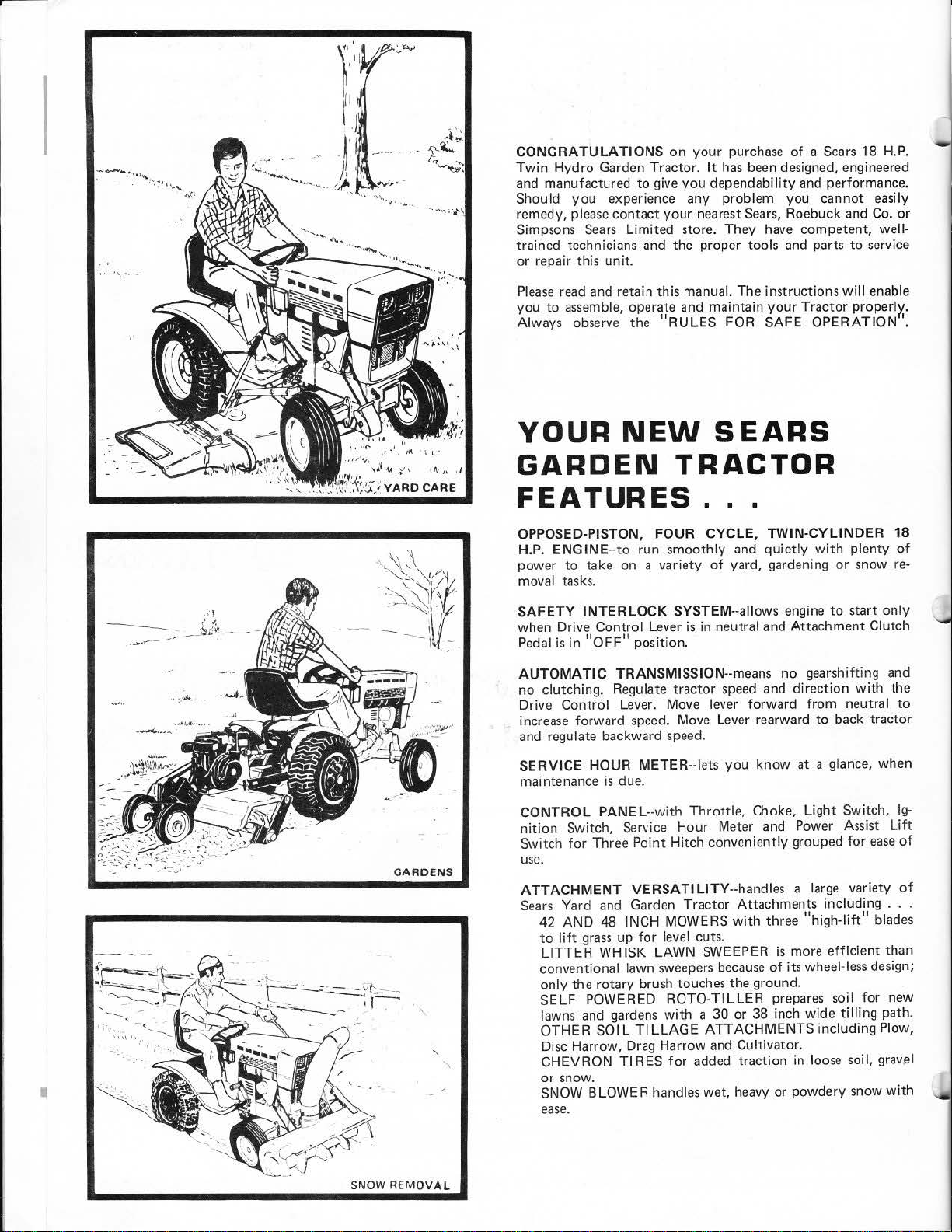
CONGRA
Twin
and manufactured
Should you experience any problem you cannot easily
remedy,
Simpsons
trained technicians and the proper tools and parts
or repair this unit.
Please
you
Always observe the
YOUR
,I
GARDEN
FEATURES
OPPOSED-PISTON, FOUR CYCLE,
H.P.
power
moval tasks.
TULATI
Hydro Garden Tractor. It
please
Sears
read
to
assemble,
ONS
on
your
purchase
has
to
give you dependability
contact
and retain this manual. The instructions
your
nearest
Limited sto
operate and maintain
NEW
re.
They have competent, well-
"R
ULES FOR SAFE OPERATION'.
SEARS
TRACTOR
...
ENGINE--to
to
take on a vari
run smooth ly
ety
of
and
yard, gardening
of a Sears
been designed, engineered
and
Sears,
Roe
buck and
your
Tractor properlx.
TWIN-CYLINDER
quietly
with
18 H.P.
performance.
Co.
to
service
will
enable
plenty
or
snow
or
18
of
re-
.n
--
_,u...
,..---,.--
I
< ,.
~£;.
__
.
_
GARDENS
SAFETY IN
when Drive Control Lever
Pedal
AUTOM
no
clutching. Regulate tractor
Drive Control Lever. Move lever forward from neutral
increase forward speed. Move Lever rearward
and regulate backward speed.
SE
RVICE HOUR METER--lets you
mainten
CONTRO
nition
Switch
use.
AT
TAC
Sears
42 AND 48 INCH MOWERS
to lift
LITTER
conventional lawn
only
SELF POWERED ROTO-TILLER
lawns
OTHER
Disc Harrow, Drag Harrow
CHEVRON Tl
or
SNOW BLOWER handles wet, heavy or powdery snow
ease
TERLOCK SYSTEM
is
in
"OFF"
ATIC TR
ance
L PANEL--with
Switch, Service Hour Meter and Power Assist
for
HMENT V
Yard
grass
the rotary brush touches the ground.
and
snow.
.
position.
ANSMISSION
is
due.
Three Point Hitch conveniently grouped
ERSATILITY
and
Garden Tractor Attachments including
up
for
sweepers
RES
level cuts.
wit
for
WHISK LAWN SWEEPER is more
gardens
SOIL TILLAGE
--a
llows engine
is
in neutral and
--means
speed
Throttle,
--handles a
with
because
h a 30 or 38 inch wide
ATTACHMEN
and
Cultivator.
added traction in l
Attachment
no gearshifting and
and direction
to
know
at a glance, when
Choke, Light Switch ,
large
three
"high-lift
of
its wheel-less design;
prepa
res
TS including Plow,
oose
to
back tractor
efficient
soil
tilling
start
only
Clutch
with
the
to
Ig-
Lift
for
ease
of
variety
soil, gravel
of
...
" blades
than
for
new
path.
with
SNOW
REMOVAL
WARRANTY.
RULES FOR SAFE OPERATION
ASSEMBLY INSTRUCTIONS
OPERATION INSTRUCTIONS
TABLE OF
.
CONTENTS
1
MAINTENANCE
1
TROUBLE SHOOTING
. 2
REPAIR PARTS
.4
INSTRUCTIONS
. . •
.6
.13
.14
ON
For
one year
will
repair any defect in material
If
this
date
of
Garden
purchase.
from the date
Tractor
is
FULL
For
90
days
from
erial
or
workma
the date ot
nship and
LIMITED
From
the 91st day
proves defective
1/12th
of
the price
Warranty service
Center
throughout
Th
is
warranty
1.
Know
the controls and
OWNER 'S
2.
Do
ad
ults
3.
Do
tance away.
Clear the
4.
and
5. Disengage all attachment clutch
fore attempting to start the engine.
6. Disengage p
fore leaving the operator's posit
7.
Disengage power
making any repairs
8. Disengage power
in
use
9.
Take all
attended, such
the attachments, shifting
brake, stopp ing the
10. Do
hill.
15°);
11. Reduce
vent tipping
wh
en changiny
2.
Stay alert
1
13.
Use
a.
Use only appr
b. Limit
c.
Do
Use
d.
th is owner's
14
. Watch
MANUAL.
not
allow
to operate
not
thrown.
.
not
Mow
never across the face.
care when pulling l
children
carry
passe
work
area
ow
er to attachments and stop the engine
poss
ibl
e precautions when leaving the vehicle u
as
stop
or
start suddenly when going
up and
speed
on sl
or
loss
direction
for hol
loads
not
counterweights
out
to
turn
manual.
for
until
in
material
of
the
is
available
the
United States.
giv
es
you
how
to
it
to
to
dow
es
oved drawbar
sharply. Use care when backing.
traffic
operate the vehicle.
without proper instruction.
ngers. Keep
of
objects which might
attachments and
or
adjustments.
attachments when transporting
disengaging the power ·take·off, lowering
into
engine
, and remov
n the face
opes
and make turns gradually
of
control.
on slopes
in the terrain and other hidden hazards.
oads
those
you
or
wheel weights when suggested in
when crossing
FULL
ELECTRIC
of
purcha~c.
used
for
90-DAY
purchase,
will
not
ONE
START
••,hen
or
workmanship in this Garden Tractor, except the battery,
commercial
this Garden
or
WARRANTY
if
any
hold
a charge,
battery
WARRANTY
one year
new
specific legal rights, and
from
or
workmanship 1nd
battery
at
your
the date
for
home,
each
full
ai
no
Sears, Roebuck and Co.
Sea
rs
sse
Chicago, I L 60684
RULES
to
stop
quickly.
children and pets a
es
and
shift
ion.
stop the engine before
neutral, setting the parking
ing the key.
of
slopes
Exercise extreme caution
.
or usin
g h
hit
ch points.
can
safely
FOR
READ
Do not
be
picked up
into
neutral
uphill
or
(not
greater than
eav
y equipment.
control.
or
near roadways.
safe
YEAR
WARRANTY
GARDEN
Tractor
rent
al
purposes, this warranty applies
is
used
ON
includ
ed
with
Sears will
replace
the
the
battery,
ON
of
purchase,
will
not
month
charge,
you
may also have
Tower
41·3
SAFE
THE
allow
dis-
bebe-
or
not
n-
down-
to
pre-
if
any
hold
a charge,
from
the date
by
simply
contacting
other
OPERATION
15. When using any attachments, never direct discharge
material toward bystanders nor
hide
16. Handle gasoline
17
18. Keep
19. Never store the equipment
20.
21. The vehicle and attachments should
22.
23. When using the vehic
24. Check the
while
a.
Use
b. Never remove the cap
a running
Wipe
Open doors
c.
fumes
. Keep the vehic
dition,
ment is in
a building where fumes may reach
Allow
To
reduce
or
excessive
ed
for
age
should
equipment.
Do
not
en
the
a.
Mow
b.
Never make a
is
running if the operator must
c. Shut the engine
unclogging chute.
Check the blade
d.
frequent intervals.
ration. Replace
TRACTOR
for
personal household purposes,
for
only
30
at
days
no
Sears
charge.
from
the
BATTERY
Garden
Tractor
at
no
proves defective in
charge.
mat·
BATTERY
battery
all nuts, bolts and screws
gine.
included
Sears
will
of
purchase.
the nearest
rights
in operation.
approved gasol ine containers.
or
up
spilled gasoline.
are
dangerous. Do
and keep safety devices in place.
the engine
damage after striking a foreign object, and the dam·
le
safe
working
fire
hazard, keep the engine free
grease.
be
repaired before restarting and operating the
change the
only
in
grass
with
replace the
which
with
hot
engine,
if
the engine
and attachments in good operating con·
to
engine governor settings
le with
daylight
cutting
off
mou
catcher
with
the Garden
battery,
Sears
store
vary
from
allow
care ·
it
is
highly
of
the fuel
or
fill
is
run
not
condition
cool before storing in any enclosure.
height adjustment
when removing the
nting bolts
bags
new
tight
with
gasoline
mower, proceed
or
in good
frequently
bags
Tractor
charging
or
Service
state
to
state.
anyone near
flammable.
tank
or
the fuel
in
run
.
an
be
for
for
add gasoline
tank indoors.
the
garage
the engine indoors.
to
be
sure the equip·
in
the tank inside
open flame
of
grass,
stopped and inspect·
or
as
artificial
dismount
follows:
light
while
grass
proper
for
tightness
wear
safety protection.
the
· exhaust
or
overspeed
.
the engine
to
do
catcher
or
deterio·
ve·
spark.
leaves
so.
of
to
·
or
at
A
LOOK
FOR
THIS SYMBOL
SAFETY PRECAUTIONS.
BECOME
ALERT! YOUR SAFETY
. 1 .
TO
POINT OUT IMPORTANT
IT
MEANS .. ATTENTION!
IS
INVOLVED .
I
CUT AWAY VIEW
FIGURE 1
::
~-:.
, I
I
rrBA
......
_
..::.::.-:.
...::
___
------
-
--
----
-
SAFETY
VENT
BATT ERY
'?':
TUBE
TT
CELL
CAP
ERY
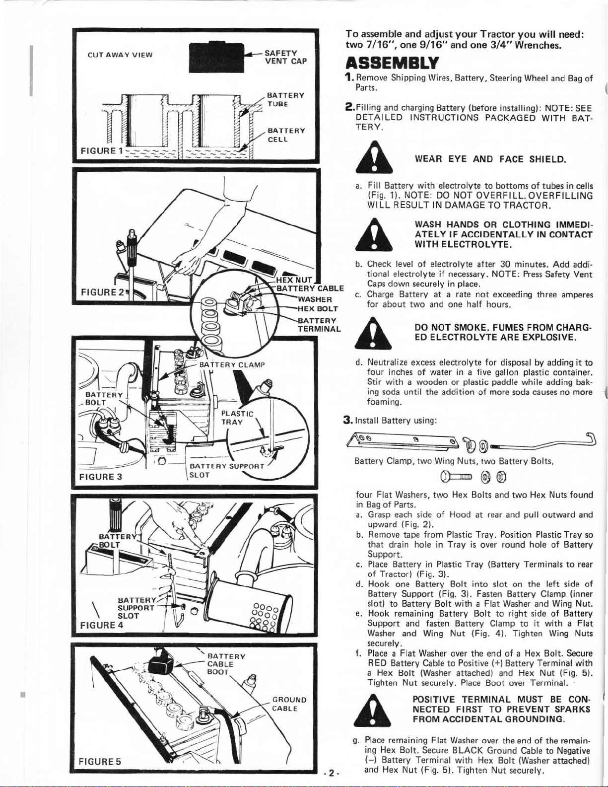
To
assemb
two
7
/16",
le
and adj u
st
one 9/16" and one 3/4" Wrenches.
ASSEMBLY
1.
Remove Shipping Wires, Batter
Parts
.
.Filli
ng
2
and charging Battery (before installing): NOT E:
DETAILED
TERY
INSTRUCTIONS PACKAGED WITH BAT-
.
WEAR EYE
A
a.
Fill Battery
(Fig.
WILL
A
b.
Check
tional electrolyte
Caps
c.
Cha
rge
for
about
with
1).
NOTE :
RESULT IN DAMAGE
level
down securely in place.
Battery at a rate
electrolyte
DO
WAS
H HANDS OR CLOTHING IMMEDIATELY
WITH
ELECTROLYTE.
of
electrolyte after
if
two
and one
your Tractor you wi
y,
Steering
AND
NOT
IF ACCIDENTALL
necessary. NOTE:
to
OVERFILL.
TO
not
exceeding three
half
hours.
Wheel
FACE SHIELD.
bottoms
TRACTOR.
30
minutes.
Press
ll
need:
and
Bag
of
SEE
of
tubes in cells
OVERF
Y IN CONTACT
ILLING
Add
addi-
Safety Vent
amperes
)
':
BAT TER Y
-BOLT
\
FIGURE 4
BAT
TERY
SUPPORT
OT
SL
DO
NOT
ED ELE CTRO
SMOKE. FUMES FROM CHARG·
LYTE
ARE EXPLOSIVE.
A
d. Neutralize
four
Stir
ing
foaming.
3 .1nstall Battery using:
Battery
four Flat
in
Bag
a. Grasp
upward (Fig.
b. Remove tape from Plastic Tray. Position Plastic Tray
that drain hole in Tray
Support.
c.
Place
of
Tractor) (Fig. 3).
d. Hook one Battery
Battery Support (Fig. 3).
slot)
e.
Hook remaining Battery
Support and fasten Battery Clamp to
Washer
securely.
f.
Place
RED Battery
a Hex Bolt
Tighten
excess
electrolyte
inches
of
water in a five gallon plastic container.
with
soda
Clamp,
a wooden
until
two
or
the addition
Wing Nuts, two Battery Bolts,
Q):::DD
Washe
rs,
two
Hex Bolts and
of
Parts.
each
side
of
Hood at rear and pull outward and
2).
Batter y in Plastic Tray (Battery Terminals
Bolt
to
Battery
and Wing
a Flat
Nut
Bolt
Washer
Cable
(Washer
securely.
with a Flat
Nut
over the end
to
for
disposal by adding
plastic paddle while adding bak-
of
more
soda
causes
@)
®
two
Hex Nuts found
is
over round hole
into
slot on the
Fasten
Bolt
(Fi
Positive (+
attached) and Hex
Place
Battery Clamp (inner
Washer
to right
g.
4).
of
)Battery
Boot over Terminal.
and Wing Nut.
side
it
Tighten Wing Nuts
a Hex
left
with a Flat
Bolt. Secure
Terminal
Nut
no more
of
Battery
to
side
of
Battery
(Fig. 5).
it
to
so
rear
of
with
•
FIGURE 5
POS
ITIVE
NECTED FIR ST TO PREV
A
g.
Plac
e remaining Flat Washer over the end
ing Hex Bolt.
(-)
Battery Terminal
. 2 . and Hex Nut (Fig. 5). Tighten
FROM ACCIDENT
Secure
TERMIN
BLACK
with
Hex
AL MUST
AL GROUNDING.
Ground
Cab
Bolt
(Washer
Nut securely.
BE
ENT
of
the remain-
le
to
CON·
SPAR
KS
Negative
attached)

4.
1nstall Steering Wheel using: Flat
Hex
Bolt
assembled
Key, and Steering
a.
Remove
Steering
b.
Insert
slide Steering
SURE WOODRUFF
SHAFT
c. Fasten
(Fig. 6). Tighten securely.
d.
Press
INITIAL
1.
Reduce
(Tires
2.
Seat
loosening Nut in
TIGHTENI NG NUT AFTER ADJUSTMENT.
SEAT PLATE HAS NOT TWISTED
MENT WITH SEAT SPRING.
Hex Bolt, Lockwasher and Flat Washer from
Shaft (Fig. 6).
Woodruff
.
with
Steering Wheel Insert
ADJUSTMENTS
Tire
pressure
were
overinflated for shipping purposes).
position
may
on
end
Wheel
Key in Keyway
Wheel
over Shaft and Key. NOTE:
KEY
Flat
Washer,
to 12 pounds in
be
adjusted forward or backward
Seat
Plate (Fig. 7). NOTE
Washer,
of
Steering Shaft; Woodruff
Insert found in
IS
SECURE IN STEER lNG
Lockwasher and
in
place.
Lockwasher, and
Bag
of
of
Steering Shaft and
Hex
front
and r
ear
WH-EN
MAKE
OUT
OF
ALIGN·
Parts.
BE
Bolt
Tires.
by
RE·
SURE
STEERING--~
WHEEL
INS
ERT
STEER I
FIGURE 6
3. The
By-Pass
rotates
Plate. Moving the Handle up or down
notch
The
By-Pass
down tight)
Index handle up
sary
to
NOTE:
Valve Handle (Fig. 8) slides in and out, and
so
that Handle
will
open
push
Do
not
or
Valve must
for
tractor
force Valve.
THIS
SAFETY
STARTING
WHILE
PEDAL
11)
IS
POSITIONS (FIG. 12).
IMMEDIATELY
THAT
ORDER.
THE
will
close By-Pass
be
tractor
at
IN
to
least
four
with
engine stopped.
TRACTOR
SWITCHES TO PREVENT
OF
THE
IS IN THE
AND
THE
" F" FORWARD
ARE
NOT
DO
PURPOSE
NOT
engage
the notch in Rotating
with
Handle engaging
Valve.
in closed
operate
notches
THE
ATTACHMENT
"ON"
DRIVE
REPLACE SWITCHES
IN
ATTEMPT TO
OF THESE SWITCHES.
pos1t1on
with
engine running.
if
it
becomes
IS EQUIPPED
TRACTOR ENGINE
POSITION (FIG.
CONTROL LEVER
OR " A"
PROPER WORKING
CLUTCH
REVERSE
DEFEAT
(rotate
neces
WIT
H
-
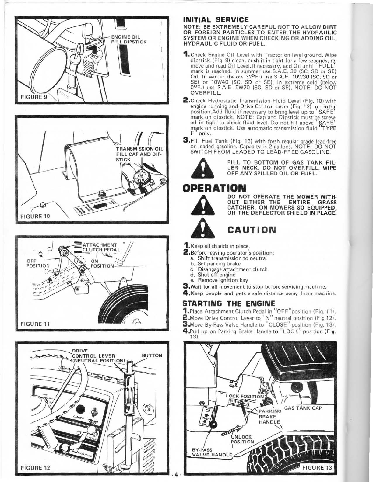
INITIAL
NOTE: BE
OR FOREIGN
SYSTEM OR ENGINE
HYDRAULIC
SERVICE
EXTREMELY
PART
FLU
ID OR
CAREFUL
ICLES
TO
WHEN CHECKING OR
FUEL.
NOT
ENTER
THE
TO A
ADDING
LLOW
HYDRA
DIRT
ULI
OI L,
C
1. Check Engine Oil Level
dipstick (Fig. 9)
move and read
ma
rk
is
Oil.
SE) or
ooF.)
OVERFILL.
2 .Check Hydrostatic Transmission
engine
position.Add
mark on dipstick. NOTE:
ed in
m,~rk
F only.
3.Fill Fuel
or
SWITCH FROM
rea
In
winter
10W40 (SC,
use
running
tight
on dipstick.
leaded gasoline. Capacity
clean, push it in tig
Oil
ched. In summer
(below
S.A.E. 5W20
and
fluid
to
check f
Tank (Fig. 13)
LEADED
FILL
LER
OFF
with
Tractor
Level.
If
necessary, add Oil
32°F.) use S.A.E. 10W30
SO
or SE).
(SC,
Drive Control Lever (Fig. 12) in neutral
if
necessary
Cap
lui
d level. Do not fill above
Use
automatic transmission
with
TO
TO BOTTOM OF GAS
NECK
. DO
ANY
SPILLED
ht
use
S.A.E.
In
SO
or
Fluid
to
bring level up
and
fresh
is
2 gallons. NOTE:
LEAD-FREE GASOLINE.
NOT
OPERATION
DO
NOT
OPERATE THE MOWER W
EITH
ER
THE
THE
DEFLECTOR
ION
A
OUT
CATCHER, ON MOWERS
OR
CAUT
A
1. Keep all shields in place.
le
avi
ng
2 .Before
a.
Shift
b.
Set
parking brake
c.
Disengage
d. Shut
e.
Remove ignition key
.W
ait
3
4.
for
Keep people and pets a safe distance away
operator's position:
transmission
attachment
off
engine
all movement
to
neutral
clutch
to
stop before servicing machine.
on l
eve
l ground . Wipe
for
a few
secf?nds,
until'
30
(SC,
extreme cold (below
SE). NOTE: DO
Level (Fig. 10)
Dipstick must
regu
lar grade lead-free
OVERFILL.
OIL OR
ENTIR
SO
SHIE LD
FULL"
SO
or
(SC,
to
"SAFE"
q~
SAFE"
fluid
"TYPE
DO
TANK FIL
FUEL.
E GRASS
EQUIPPED,
IN
PLACE.
from
machine.
sc
re-
SE)
SO
or
NOT
with
rew·
NOT
WIPE
ITH
·
-
FIGURE
FIGURE
11
12
STARTING
1.
Piace
Attachment Clutch
2 .Move Drive
3.
Move
By-Pass Val
4.Pull
up
13).
on Parki
BY-PASS
VE HANDLE
THE ENGIN
Co
ntrol
Lever
ve
Handle
ng
Brake Handle
Pedal
to
to
E
in
"OFF"position
"N"
neutral
"CL
OSE
to
"LOCK"
(Fig. 11).
posit
ion (F ig.12).
" position (Fig. 13
position (Fig.
).

5.
Push
Clutch-Brake
6.
Move
Throttle
7.
Pull Choke
8.
Turn Ignition Key
starts (Fig. 15).
Pedal
Control Lever
out
(Fig. 15).
Release
into
to
"START"
key
"BRAKE"
to
middle position (Fig. 15).
into
position (Fig. 14).
position
"ON"
position.
until
Engine
BRAKE
DRIVE
CLUTCH-BRAKE
PEDAL
NOTE:
FOR MORE
engine
Control Lever
try
NOTE: The Power Assist
lowers
Point Hitch (optional equipment).
WARMING UP
Move Throttle Control Lever
Choke in
WARM
When
in middle position, Choke may
DO
NOT RUN STARTER CONTINUOUSLY
does
again.
an
THAN
not
attachment when
THIRTY
start after
to
"F"
fast
several
pos
Lift
THE
to
as
engine warms. NOTE:
UP
FOR A FEW MINUTES BEFORE
restarting a warm engine,
ALWAYS WEAR SUBSTANTIAL FOOTWEAR
CLOTHING
IN MOVING PARTS.
LEARN TO START,
YOUR TRACTOR
SPACE.
move
AND
THAT
SECONDS
attempts, move
ition,
wait
Switch (Fig. 15)
used
with
AT
a few minutes, and
an
Electric Three
ENGINE
"s" slow
ALLOW
Throttle Control
not
AVOID
COULD GET CAUGHT
STOP
IN
pos1t1on. Push
ENGINE TO
OPE~ATING
have
to
LOOSE
AND
A LARGE,
A TIME.
throttle
raises
Lever
be
used.
FITTING
REVERSE
OPEN
If
or
.
TRACTOR
1.
With engine running and warm, move
to
Lever
2.
Push
position.
3.
Press
move
4.
Adjust Throttle Control Lever
that engine is
NOTE: Always operate power-driven equipment
tary Mower, Snow Thrower, etc. at full
otherwise specified in the attachment Owners Manual. Always
select a
the attachment being
middle position.
down on Parking Brake Handle
Button
Lev
er
safe
ground travel
OPERATION
(Fig. 12) on Drive Control L
forward and tractor
THE
SITIVE
MOVE
LY.
not
overloaded.
used.
DRIVE
CONTROL LEVER IS SEN-
TO THE SLIGHTEST MOVEMENT.
DRIVE
CONTROL LEVER SLOW-
to
desired engine
speed
that
will
5. To back-up, return Drive Control Lever
position
Lever
slowly.
and
to
"SLOW"
tractor
will
stop. Reduce
position,
NEVER PLACE
IN
OR
MENT
WHILE TRACTOR OR
ATTACHMENT
pull
UNDER
OR NEAR
ANY
Drive Control Lever back
YOUR HANDS OR FEET
ANY
IS RUNNING.
Thrott
le Con
tro
to
"UN
LOCK"
ever
and slowly
will
begin
to
move.
speed
so
such
as
Ro-
Throttle
POWERED ATTACH-
speed
unless
suit the terrain and
to
"N"
neutral
Throttle
MOVING PART
ANY
Control
POWERED
STOPPING
1.
l
Return Drive Control Lever
2.Reduce
3.P
iace
Attachment Clutch Pedal in
4.
Place
Parki
A
~
5.
Turn Ignition Key to
NOTE:
STOPS
CONTROL LEVER TO
THE CLUTCH-BRAKE PEDAL
THE TRACTOR
IN THIS POSITION. WHEN FOOT
PEDAL,
SPEED.
-
5-
USE
ONLY. FOR
TRACTOR
YOUR
Throttle
ng
CLUTCH-BRAKE PEDAL FOR EMERGENCY
Control
Brake in
MAKE
HOLD
REMOVE
TOR TO
NORMAL
AS
LONG AS THE PEDAL
NEVER
TO SLOW TRACTOR. ALWAYS
CLUTCH-BRAKE PEDAL
FORWARD
LEVER RETURNS TO
TRACTOR
to
"N''
neutral position.
Lever
to
"s" slow position.
"OFF"
"LOCK"
SURE PARKING BRAKE
TRACTOR SECURE.
"OFF"
PREVENT
NEUTRAL
WILL
USE
position.
position.
KEY WHEN LEAVING TRAC-
STOPS,
BY
HALF-WAY
RETURN TO
FOOT PEDAL
SO
THAT
position.
UNAUTHORIZED
RETURN
HAND
DEPRESSING
DECLUTCHES
IS
REMOVED FROM
TRAVELI
AS
ALL
DRIVE
NEUTRAL.
WILL
USE.
DRIVE
IS
HELD
NG
A CLUTCH
PUSH
THE
WAY
CONTROL
TRANSPORTING
TOWING IS
power transmission, internal
is
towed.
controls
1. Drive Control Lever in
2.
By-
3.
Parking Brake Handle pushed
tion.
Use
trailer to transport tractor
TRACTOR
1.
Avoid stopping on hills.
as
Pass
NOT
RECOMMENDED. As with any hydraulic
Push
tractor by hand
follows:
Valve in
OPERATION
DO
WI
TH SLOPES GREATER
DO
"N"
"OPEN"
NOT
NOT
YOUR
damage
neutral.
position.
down
for
DRIVE
DRIVE
TRACTOR
can
result when vehicle
only
short distances
to
"UN
long distances.
ON
UP
OR
THAN
ACROSS
LOCK"
HILLS
DOWN
15°,AND
ANY
with
posi-
HILLS
SLOPE.
STARTING
WITH
If
your
recharged.
follow
PED
THE OTHER
NEGA
A
1.
Connect
termina
cha
2.
Connect one
(-)
3.
Connect the other end
of
Tank
A
LOW
Battery
this procedure. NOTE: YOUR TRACTOR
WITH A 12
TIVE
ssis).
terminal
good CHASSIS GROUND
or Batt
is
If
"Jumper Cables" are
VOLT
VEHICLE
GROUNDED SYSTE M.
LEAD-ACID
PLOSIVE GASES.
AND
BATTERIES.
AROUN
each
end
ls
of
each
end
of
ery).
YOUR
BATTERY
too
low
to start the engine,
NEGATIVE
MUST ALSO
BATTERIES GENERATE EX-
SMOKING MATERI
D BATTERIES.
of
the RED cable
battery (taking
of
the BLACK cable
"GOOD"
battery.
of
the cable
TRACTOR
it
used
for
emergency starting
GROUNDED SYSTEM.
BE
KEEP SPARKS,
ALS
ALWAYS
to
the F"OSITIVE (+)
care
not
to
to
ENGINE BLOCK
on
tractor (away.
IS
A 12 VO LT
AWAY
SHIELD
to
short against
the NEGATIVE
sho
uld
EQUIP-
FLAME,
FROM
EYES
from
Gas
be
a.
If
slowing
slowly.
b.
If
stopping
neu
tral.
c.
Engage
d.
To resume travel push Drive Control Lever slowly for-
ward.
e.
Release
2.
Make."'ll turns gradually.
is
necessary,
is
necessary,
Parking Brake.
Parking Brake
~~
~~~~
pull Drive Control Lever back
pull Drive Control Lever
as
forward movement begins.
--~~-SYSTE
M
INDICATOR
to
4.
Disconnect cables in reverse order :
a.
Engine Block
b. Negat
c.
ive
Positive terminals.
or
terminal
DO
TE
RY
chassis.
of
NOT
TO
"GOOD"
USE
MAINTENANCE
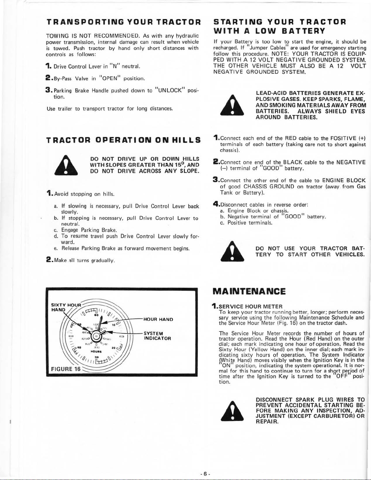
1.
SERVI
CE
HOUR METER
keep
To
sary
the Service Hour Meter {Fig. 16)
The
tractor operation.
dial;
Sixty Hour
dicating sixty hours
~White
'oN"
mal
time
tion.
your tractor running better, longer; perform
service using the following Maintenance Schedule and
Service Hour Meter records the number
each
mark indicating one hour
Hand) moves visibly when the Ignition Key
pos
ition
for
this hand
after t
Read
the Hour (Red Hand)
(Yellow Hand) on the inner dial;
he Ignitio
of
operation. The System Indicator
, indicating the system operational.
to
continue
n Key is turned
YOUR
START
on
to
turn
battery.
TRA
CTOR
OTHER VE
the tractor dash.
of
operation.
for a shwt
to
the
of
on
each
'OFF'
HICLE
hours
the outer
Read
period
BA~
neces-
of
the
mark in-
is
in the
It
is
nor-
of
posi-
S.
DISCONNECT SPARK PLUG WIRES TO
PREVENT ACCIDENTAL S
FORE
A
-
6-
JUSTMENT (EXCEPT CARBUR ETOR) OR
REPAIR.
MAKING
ANY
TARTING BE-
INSPECTION, AD-
FIRST
~
HOURS
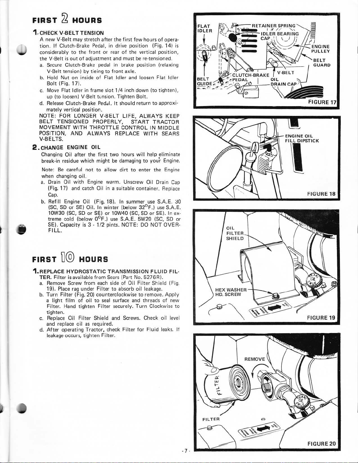
1. CHECK V-BEL T TENSION
A new V-Belt may stretch after the
If
tion.
considerably
he
t
a.
b. Hold
c.
d.
NOTE: FOR LONGER V-BE LT
BELT
MOVEME
POSITION,
V-BELTS.
2 . CHANGE
Changing Oil after the
break-in residue which
Note:
when changing
a.
b. Refill Engine Oil (Fig. 18). In summer
Clutch-Brake Pedal. in drive position (Fig. 14)
to
the
front
or
V-Belt
is
out
of
adjustment
Secure
V-Belt tension) by tieing
Bolt
Move Flat Idler in frame slot 1/4 inch down (to tighten
up (to loosen) V-Belt tt:nsion. Tighten Bolt.
Release
mately vertical position .
Clutch-Brake pedal in brake position (relaxing
to
Nut
on inside
(Fig.
17).
Clutch-Brake Pedul.
TENSIONED PROPERLY, START
NT
WIT
AND
E
NGINE
Be
careful
Drain Oil
(Fig. 17)
Cap.
(SC,
10W30 (SC,
treme cold (below
SE). Capacity
FI
LL.
SD
or
with
and
SE)
of
Flat Idler and loosen Flat Idler
H THROT
ALWAYS REPLACE
OIL
first
might
not
to
allow
oi
l.
Engine warm. Unscrew Oil Drain
catch Oil in a suitable container. Replace
Oil. In
SD
is
or
3 ·
SE)
0°F
1/2
winter
or
.)
first
few hours
rear
of
the verti
and
must
front
axle.
It
should return
LIFE,
TLE
CONTROL
two
hours
be
damaging
dirt
to
(below
10W40
use S.A.E.
pints. NOTE:
(SC,
be
ALWAYS
will
enter the Engine
32°F
5W20 (SC,
of
opera-
cal
position,
re-tensioned.
to
approxi-
TRACTOR
IN MIDDLE
WITH
to
SO
DO
SEARS
help eliminate
your
Engine.
use
S.A.E. 30
.)
use
or
SE). In ex-
NOT
OVER-
is
),
KEEP
Cap
S.A.
E.
SD
or
E
NGIN
F
ILL
'
FIGURE 17
E OIL
DIPSTICK
FIGU
RE
18
FIRST
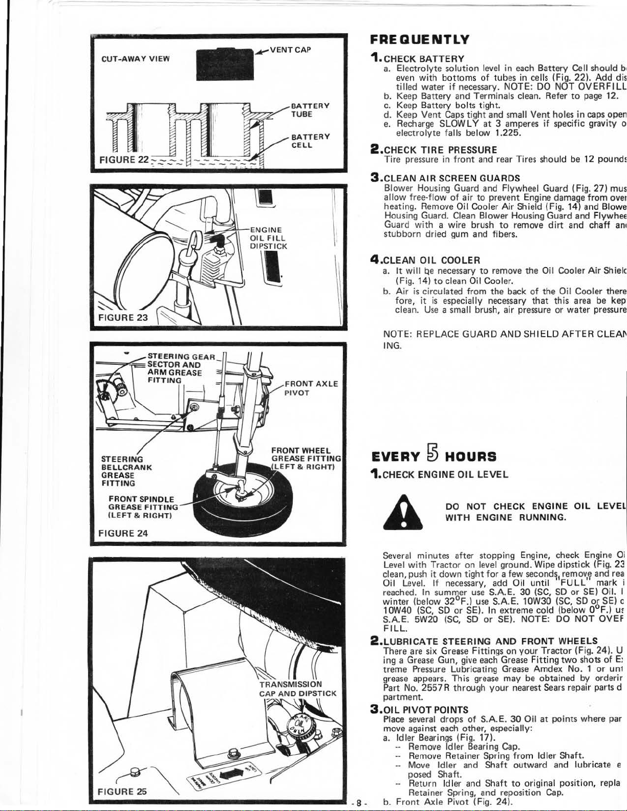
1.REPLA
TER. Fi
a.
b.
c.
d.
D@
CE HYDROSTA
lter
Remove Screw
19).
Place
Turn Filter
a
light
Filter. Hand tighten
tighten.
Replace Oil Filter Shield and Screws. Check oil level
and replace
After
operating Tractor, check
leakage
HOURS
is available
rag
(Fig. 20) counterclockwise
film
of
oil
occurs, tighten Filter.
TIC TRANSM ISSION FL
from
Sears
from
each
Filter
to
seal
Filter
side
to
surface and threads
securely.
under
oil
as
required.
(Part No. 5276R).
of
Oi I Fi Iter Shield (Fig.
absorb oil leakage.
to
remove.
Turn
Filter for
Clockw
Fluid
UID
of
leaks.
FIL
App
new
ise
·
ly
to
FIGURE 19
If
-1·
FIGURE
20
CUT-AWAY
VIEW
.....-VENT
CAP
BATTERY
TUBE
BATTERY
CELL
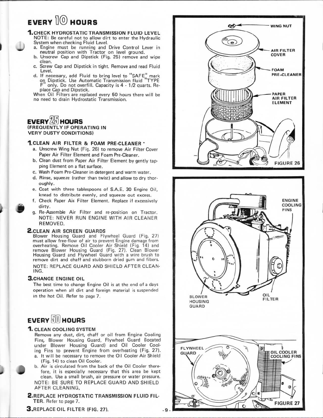
FREQUENTLY
1.
CHECK
a. Electrolyte solution
b.
c. Keep Battery bolts tight.
d.
e. Recharge
2.CHE
Tire pressure
BATTERY
level
even with bottoms of
water if necessary. NOTE:
tilled
in each Battery Cell should be
tub
es
Keep Battery and Terminals clean. Refer
Keep Vent Caps tight and small
SLOW
LY
at
3 amperes if specific gravity of
electrolyte falls below 1.225.
CK
TIRE PRESSURE
in
front and rear Tires should be 12 pounds.
in
cells (Fig. 22). Add dis·
DO NOT OVERFILL.
to
page 12.
Vent holes in caps open .
STEERING
BELLCRANK
GREASE
FITTING
FRONT
GREASE
(
FIGURE
SPINDLE
LEFT & RIGHT)
24
-'-'·--""""'-
FITTING
~1.&
~~-loNGINE
OIL
FILL
DIPSTICK
I
3.CLEAN
AIR SCREEN GUARDS
Blower Housing Guard and Flywheel Guard (Fig. 27) must
allow free·flow of air to prevent Engine
heating. Remove
Oil
Cooler
Air
Shield (Fig. 14) and Blower
dama~;~e
from over-
Housing Guard. Clean Blower Housing Guard and Flywheel
Guard with a wire brush
to
remove dirt and chaff and
stubborn dried gum and fibers.
4.CLEAN
a.
b.
NOTE:
OIL COOLER
It
will qe necessary
(Fig. 14)
Air
fore,
clean.
to
clean O
is circulated from
it
is
especially necessary
Use
a small brush, air pressure or water pr
REPLACE
to
remove the O
il
Cooler.
the
back of the
GUARD AND
il
Cooler Air Shield
Oil
that
Cooler there-
this area be
SHIELD AFTER CLEAN
lNG.
EVERY
1.CHE
0
HOURS
CK
ENGINE OI L LEVEL
DO
NOT
WITH
CHECK
ENGINE OIL
ENGINE RUNNING.
kept
ess
ure.
LEVEL
..
___________________
.. -8-
Several minutes after stopping Engine, check
Leve
l with Tractor on
clean, push
Oil
reached.
Level.
it
down tight for a few
If
necessary, add
In
sum~er
winter (below 32 F.)
1
OW40
(SC,
S.A.E. 5W20
F
ILL.
SO
(SC,
level
ground.
use S.A.E.
use
or SE).
S.A.E. 10W30
In
SO
extreme cold (be
or SE). NOTE: DO NOT OVEF
Wipe
second~
Oil
until FULL' mark i
30
(SC,
Engine
dipstick (Fig. 23
remov~
1
SO
or SE) Oil. I
(SC,
SO
low
0 F.)
2 . LUBRICATE STEERING AND FRONT WHEELS
There are six Grease
ing a Grease Gun,
treme Pressure Lubricating Grease Amdex
grease appears. This grease may be obtained
Part
No.
2557 R through your nearest Sears repair parts d
Fittings
give
on your Tractor (Fig. 24). U
each Grease Fitting
two
shots of E:
No.
1 or
by
partment.
3.0IL
PIVOT POINTS
Place several
move
aga
a.
Idler Bearings (Fig. 17).
--
Remove Idler Bearing Cap.
drops of S.A.
inst each other, especially:
E.
30
Oil
-- Remove Retainer Spring from Idler
••
Move
Idler and Shaft outward and lubricate e
at
points where par
Shaft.
posed Shaft.
--
Return
Retainer Spring, and reposition Cap .
b.
Front Axle Pivot (Fig. 24).
Idl
er and Shaft
to
original
posi
tion, repla
and rea
o6
SE) c
un1
orderir
Oi
U!
EVERY
1.CHECK
NOTE:
System when checking Fluid Level.
a.
b. Unscrew
c.
d.
When
no
TI®
HOURS
HYDROSTATIC
Be
careful
Engine
neutral position
clean.
Screw
Level.
If
on Dipstick.
F"
place
need
must
be
Cap
and Dipstick (Fig. 25) remove and
Cap
and Dipstick
necessary, add Fluid
only. Do
Cap
Oil Filters are replaced every
to
Use
not
and Dipstick.
drain Hydrostatic Transmission .
TRANSMISSION
not
to
allow
running and Drive
with
Tractor
Automatic
overfill. Capacity
dirt
on
in
tight. Remove and read
to
bring level
Transmission
FLUID
to
enter the Hydraulic
Control
level ground.
to
"SAFE"
is
50
fluid
4 - 1/2 quarts.
hours there
LEVEL
Lever in
wipe
Fluid
mark
"TYPE
Re-
will
be
~,.-------WING
AIR
COVER
FOAM
PRE-CLEANER
.---PAPER
AIR
ELEMENT
NUT
FILTER
FILTER
EVERY
(FREQUENTLY
VERY
1.CLEAN
a.
b. Clean dust
c.
d. Rinse,
e. Coat
f.
g.
2
.CLEAN
Blower Housing Guard
must
overheating. Remove Oil Cooler
remove
Housing Guard and Flywheel Guard
remove
NOTE: REPLACE
ING.
3 .CHANGE ENGINE
The best time
operation when
m the
~
HOURS
IF
OPERATING
DUSTY
Unscrew Wing
Paper
ping
Wash
oughly.
knead
Check
dirty.
Re-Assemble
NOTE: NEVER RUN ENGINE WI
REMOVED.
allow
CONDITIONS)
AIR
FILTER & FOAM
Nut
(Fig. 26)
Air
Filter Element and Foam Pre-
from
Paper
Air
Element on a
Foam Pre-Cleaner in detergent and warm water.
squeeze
with
to
distribute evenly, and
Paper
AIR
free-flow
Blower Housing Guard (Fig. 27). Clean Blower
dirt
and
hot
Oil. Refer
flat
surface.
(rather than twist) and
three tablespoons
Ai~
F
ilter
Element. Replace
Air
Filter and re-position on Tractor.
SCREEN GUARDS
chaff and stubborn dried gum and fibers.
to
change Engine Oil
all
and
of
air
to
GUARD
OIL
dirt
AND
and foreign material
to
pag
e 7.
IN
PRE-CLEANER •
to
remove
Filter Element
of
Flywheel Guard (Fi
prevent Engine
Air
SHIELD
Air
Filter
Cleaner.
by
allow
to
S.A.E.
30
Engine Oil,
squeeze
is
out
if
excessively
TH
AIR
CLEAhlER
Shield (Fig. 14) and
with
damage
a wire brush
AFTER
at the end
is
Cover
gently tap-
dry
thor-
excess.
g.
27)
from
CLEAN-
of
a days
suspended
to
FIGURE
ENGINE
COO
26
LING
EVERY
1.
CLEAN
Remove any dust,
Fins, Blower Housing Guard, Flywheel Guard (located
under Blower Housing Guard) and Oil Cooler Cooling Fins
a.
b.
NOTE: BE SURE TO REPLACE
AFTER
2 .REPLACE
TER . Refer
3.REP
~(D
COOLING
to
It
will
be necessary
(Fig. 14)
Air
is
circulated
fore,
it
clean.
Use
CLEAN
HYDROSTATIC
LACE
OIL
HOURS
SYSTEM
dirt,
chaff
or
oil
prevent Engine
to
clean Oil Cooler.
is especially necessary
a small brush, air pressure or water pressure.
to
page
FILTER
to
from
ING,
7.
from
overheating (Fig. 27).
remove the Oil Cooler
the
back
of
that
GUARD
TRANSMISSION
(FIG. 27). - 9 -
from
Engine Cooling
Air
Shield
the Oil Cooler there-
this
area
be
kept
AND
SHIELD
FLUID
FIL
-
.__;;;;:;__;;;;.iiijii;
......
~~~·----·
FIGURE
AIR
INTAKE
HOSE
FIGURE
28
28A
EVERv
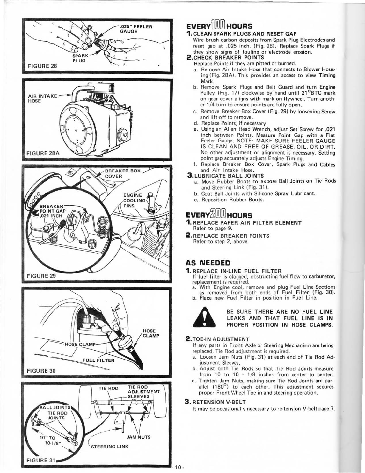
1.
CLEAN
Wire brush carbon deposits
\
reset
they show
2.CH
b. Remove
c.
3.LU
TI[OOJ
HOURS
SPARK PLUGS A
gap
at .025 inch. (Fig. 28). Replace Spark
signs
ECK
Replace Points
a.
d. Replace Points,
e.
f.
a.
b. Coat Ball Joints
c.
BREAKER
Remove
ing (Fig.
Mark.
Pulley (Fig. 17) clockwise
on
gear
er 1/4 turn
Remove
and
lift
Using
inch between Points. Measure Point Gap
Feeler Gauge. NOTE:
IS
CLEAN
No other adjustment
point
gap
Replace
and Air Intake Hose.
BRICATE BALL
Move Rubber Boots
and
Steering Li
Reposition Rubber Boots.
of
if
they
Air
Intake
28A).
This provides
Spark
cover aligns
to
ensure points
Breaker Box
off
to
remove.
an
Allen
AND
accurately adjusts Engine Timing.
Breaker Box Cover. Spark
nk
ND
RESET GAP
from
Spark Plug Electrodes and
foulin!l
Plugs
if
Head
with
or
POINTS
are
Hose
with
necessary.
FREE OF GREASE, O
JOINTS
(Fig.
electrode erosion.
pitted
or burned.
that connects
an
access
and Belt Guard and
by
hand
mark on flywheel. Turn anoth-
are
fully
CovP.r
(Fig. 29) by loosening Screw
Wrench, adjust Set Screw
MAKE
or
to
Silicone Spray Lubricant.
SURE FEELER
alignment
expose Ball Joints on Tie Rods
31
).
Plugs
to
Blower Hous·
to
view
Timing
turn
Engine
until
21°BTC
open.
for
with a Flat
GAUGE
IL,
OR
DIRT.
is
necessary. Setting
Plugs
and
Cables
if
mark
.021
EVERY
1. REPLACE PAPER
2 . REPLACE
AS
1. R
a.
2. TOE-IN ADJUS
c.
3. RETENSION
~
HOURS
AIR
FIL
TER
Refer
Refer
to
page
9.
BREAKER
to
step 2, above.
POINTS
ELEMENT
NEEDED
EPLA
CE IN-
LINE
If
fuel filter
replacement
With Engine cool, remove and plug Fuel
as
b.
Place
If
any parts in Front Axle
replaced. Tie Rod adjustment is required.
a.
Loosen
justment
b. Adjust
from
Tighten Jam Nuts. making sure Tie Rod Joints
allel
proper
It
may
is
is
removed
new Fuel F
Jam
Sleeves.
both
1 0
to
(180°)
Front
V-
be
occasionally necessary
FUEL FILTER
clogged, obstructing fuel
required.
from
both
ends
ilter
BE SURE THERE
LE
AKS
AND
PROPER POS
TMENT
Nuts (Fig. 31) at
Tie
Rods
1 0 -
to
Whee
BELT
so
1/8
each
other. This adjustment
l Toe-in and steering operation.
of
in position in Fuel Line.
ARE
THAT
ITION
or
Steering Mechanism
each
that Tie Rod Joints
inches
from
tore
flow
to
carburetor,
Fuel
FUEL
IN
-tension V-belt
Line
Filter
(Fig. 30).
NO
FUEL
LINE
HOSE CLAMPS.
are
end
of
Tie Rod Ad·
center
to
Sections
LINE
IS
IN
being
measure
center.
are
par·
secures
page
7.
 Loading...