

Sears 917.257061,GT/18 Owner's Manual

~
MODEL NO.
917.257061
OW
R'S
MANUAL
Assembly
aintenance
" "
Op
~
eratio~
Repair
--','.:',:-;.:
Parts
.,
",.
~
~~
IMPORTA
R D RULE FOR
AFE
A D I TRUCTIO
CAREFULLY
Sears.
Roebuck
OPERATIO
T:
and
Co
.•
Chicago.
Ill.
60684.
U.
S.A. and
Simpsons
Sears
Limited.
Toronto.
Canada

CONGRATULATIONS
Twin Garden
manufactured
Should
please
contact
sons Sears Limited
technicians and
this
unit
you
experience
.
Tractor.
to
give
your
nearest
store.
the
proper
on
your
purchase
It
has been designed, engineered
you
dependability
any
problem
Sears,
They
tools
you
Roebuck
have
and
of
and
cannot
and Co.
competent,
parts
to
service
a Sears
easily
GT/18
and
performance.
remedy,
or
Simp-
well-trained
or
repair
.....;c
.--~-
~l=-
-
---
~
GARDENS
-._
.'
Please read and
you
to
assemble,
"Always
observe
YOUR
GARDEN
FEATURES ...
OPPOSED-PISTON,
'
IV
,. , { H.P. ENGINE--to
power
to
tasks.
SAFETY
when
Clutch Pedal
ALL-GEAR
speeds--to
the
ing.
SERVICE
maintenance
CONTROL
nition
Three
ATTACHMENT
Sears Yard
take
INTERLOCK
tractor
let
job.
Auto-type
HOUR METER--Iets
Switch,
Point
42
AND
to
lift grass
LInER
conventional
only
SELF
lawns and gardens
OTHER
Disc Harrow, Drag Harrow
CHEVRON
or
SNOW BLOWE R
ease .
WHISK LAWN SWEEPER
the
rotary
POWERED ROTO-TILLER prepares soil for new
SOIL
snow.
retain
operate
the
NEW
this manual.
and
"RULES
GT
The
maintain
FOR
/18
instructions
your
Tractor
SAFE
OPERATION"
TWIN
TRACTOR
FOUR
run
on
a variety
Clutch-Brake Pedal
is
in
"OF
TRANSMISSION--six speeds forward,
you
select
differential helps guard
is
due
.
PANEL--wi
Service Hour Meter and Electric Lift
Hitch
conveniently
VERSA
and
Garden
48
INCH MOWERS
up
for level
lawn sweepers because
brush
TILLAGE
TI RES for
handles
CYCLE, TWIN-CYLINDER
smoothly
SYSTEM--allows engine
F"
position.
the
th
TI LlTY--handles a large variety of
Tractor
touches
with a 30
and
of
yard, gardening
proper
Throttle,
grouped
cuts
.
ATTACHMENTS including Plow,
and
added
wet,
quietly
is
depressed
match
you
know
Choke, Light
Attachments
with
three
of
the
ground
to
38
inch wide tilling path.
Cultivator.
traction
heavy
or
with
or
and
for
the
against
at
a glance,
for ease
including.
"high-lift"
is
more
its wheel-less design;
.
in loose soil, gravel
powdery
will
enable
properly.
plenty
snow
removal
to
start
Attachment
two
reverse
terrain
turf
Switch,
Switch
of
use.
blades
efficient
snow
,
18
of
only
and
scuff-
when
Ig-
for
than
with
NOW
REMOVAL
WARRANTY
RULES
FOR SAFE
ASSEMBLY
OPERATION
For
one
will
repair
If
this
Garden
date
of
For
90
erial
or
From
the
proves
1
/12th
Warranty
Center
This
warranty
OPERATION
INSTRUCTIONS
INSTRUCTIONS
ON
year
from
the
defect
date
in
is
any
Tractor
purchase.
FULL
days
from
the
workmanship
date
and
LIMITED
91
st
day
defective
of
the
service
throughout
in
price
gives
until
material
of
the
is
available
the
you
United
TABLE
OF
CONTENTS
1
MAINTENANCE
1
TROUBLE
.2
REPAIR
.4
FULL ONE YEAR WARRANTY
ELECTRIC
of
purchac~,
material
used
or
for
commercial
SO-DAY
ot
purchase,
will
not
hold a charge,
one
year
from
or
workmanship
new
battery
at
your
home,
States.
specific
legal
START
\iJhcr~
this
workmanship
if
any
Garden
or
rental'
WAR
battery
Sears
in
this
purposes,
RANTY
included
will
WARRANTY
the
date
of
for
each
rights,
and
at
and
Sears,
Sears
BSC
Ch icago, I L
full
no
you
Tower
41-3
purchase,
will
not
month
charge,
may
Roebuck
GARDEN
Tractor
replace
Garden
this
with
the
is
used
Tractor,
the
ON
if
any
hold a charge,
from
the
date
by
simply
contacting
also
have
other
and
Co.
60684
warranty
ON
battery,
battery
INSTHUCTIONS
SHOOTING
PARTS.
TRACTOR
for
personal
except
the
applies
BATTERY
Garden
Tractor
at
no
charge.
BATTERY
included
Sears
will
the
replace
nearest
which
of
purchase,
rights
household
battery,
for
only
proves
with
the
the
Sears
vary
from
.
purposes,
at
no
30
days
defective
Garden
battery,
store
state
Sears
charge.
from
in
Tractor
charging
or
Service
to
state.
.6
11
12
the
mat·
e
Know
1.
OWNER'S
Do
not
2.
adults
Do
not
3.
tance
Clear
4.
and
thrown.
5.
Disengage all
fore
attempting
6.
Disengage
fore leaving
7.
Disengage
making
Disengage
8.
rn
use.
Take
9.
attended,
the
attachments,
brake,
10.
Do
not
hrll. Mow
0
15
);
Reduce
11.
vent
when
Stay
12.
13.
Use
a. Use
b. Limit loads
c.
Do
d. Use
this
14.
Watch
the
controls
MANUAL.
allow
chrldren
to
operate
carry
away.
the
all possible
never across
tipping
alert
care
passengers. Keep
work
attachment
power
the
power
any
repairs
power
such
stopping
stop
or
up
and
speed
on
nr loss of
changing
for holes
when
only
approved
not
turn
counterweights
owner's
out
fOI
RULES FOR
and
how
to
stop
quickly.
to
it
area
to
to
operator's
to
to
precautions
as disengaging
Shlftlllg
the
start
down
direction
pulling loads or uSing heavy
to
sharply.
manual
traffic
operate
without
of
objects
clutches
start
the
attachments
attachments
or
adjustments.
attachments
Into
engine,
suddenly
the
the
face.
slopes
and
control.
on
In
the
terrain
drawbar
those
you
or
wheel
when
proper
children
which
engine.
position.
when
the
neutral,
and
removing
when
face
make
slopes.
can
Use
care
crossrng
the
vehicle.
instruction.
and
might
and
shift
and
stop
and
stop
the
when
transporting
leaving
power·take-off,
setting
the
gOing
of
slopes
(not
turns
other
points.
safely
when
when
or
LOOK FOR
SAFETY
BECOME
gradually
extreme
control.
Exercise
and
hitch
weights
READ
Do
not
pets a safe
be
picked
into
neutral
the
engine
engine
the
vehicle
lowering
the
parking
key.
uphill
or
greater
caution
hidden
hazards.
equipment.
backing.
suggested
near
roadways.
THIS
PRECAUTIONS.
ALERT'
SAFE
THE
allow
dis-
up
bebe·
before
or
not
un·
down-
than
to
pre·
15. When using
16.
17. Keep
18. Keep all
19. Never
20.
21.
22.
23.
in
24.
SYMBOL TO POINT
YOUR
SAFETY
OPERATION
material
hicle while
Handle gasoline
a. Use
b, Never
a
running
Wipe
c.
Open
fumes
dition,
ment
building
a
Allow
To
reduce
or
e xcessi
The
vehicle
ed
for
age
should
equipment.
Do
not
the
engine.
When using
a. Mow
b. Never
is
c.
Shut
unclogging
d.
Check
frequent
Check
ration.
IT
MEANS··
any
toward
in
approved
remove
or
up
spilled gasoline.
doors
are
the
vehicle
and
keep
nuts,
is
in
safe
store
the
where
the
engine
fire
ve
grease.
and
damage
be
change
the
only
make a cuttir-
running
the
engine
the
Intervals.
the
grass
Replace
OUT
An
IS
IN\!
bystanders
operation.
with
gasoline
the
hot
if
dangerous.
and
safety
bolts
working
equipment
hazard,
attachments
after
repaired
the
vehicle
in
daylig~,
if
the
chute.
blade
catcher
IMPORTANT
NTION'
lED.
attachments,
care
cap
engine,
the
engine
attachments
devices in
and
screws
condition.
fumes
may
to
cool
keep
striking
befofe'!iestarting
engin
w;
oh
;,helY.'-emcWf"-9
" .
mountin~~pf~~~
bags frequaB,ri,"I,for
with
new
never
nor
allow
- it
is
highly
containers.
of
the
fuel
or
fill
is
run
Do
not
tight
with
gasoline
reach
before
the
engine
should
a foreign
yovernor
,IIOWE
Ir
if!
9
,ight
~AU$tment
'ratormuSt
c'
~.·.c
-1.,
bags'. ':'.
direct
anyone
flammable.
tank
or
the
fuel
in
the
run
place.
storing
ou
:~''\.
1~~~·
garage -exhaust
the
in
good
to
be
in
an
open
in
free
be
stopped
object,
and
settings
proceed
artificial light.
while
dismount
the
t<i'
proper
"
5i,
safety
discharge
near
add
gasoline
tank
engine
operating
sure
the
the
tank
flame
any
enclosure.
of
grass, leaves
and
and
operating
or
overspeed
as
follows:
the
to
grass
catcher
tightness
wear
or
protection.
the
indoors.
indoors.
con-
equip-
inside
or
spark.
inspect-
the
dam-
the
engine
do
deterio-
of
ve-
to
so,
or
at

CUT
AWA Y VIEW
VENT
CAP
To assemllie
one
7/16".9/16"
NOTE: Right
mined
fr om
dnti
adjust
and 3/4"
Hand
operator's
YOllr Tractor you
Wrench
(R .
H.l and
position.
Left
will
Hand
need
(L.H.l
are
deter·
HOOD
LATCH
FIGURE
BATTERY
.
"7'
TUBE
·
0::
.
.BATTERY
CELL
-M
-
----
------
-
---_
~
._-
2
ASSEMBLY
1.
Remove
of
2. Filling
DETAILED
TERY.
Parts.
Shipping
and
charging
INSTRUCTIONS
Wires. Battery.
A WEAR
a. Fill
3.
(Fig.
WILL
A
b.
Check
tional
Caps
c.
Charge
for
A
~
d.
Neutralize
four
Stir
ing
foaming.
Install
Battery
securely,
about
with a wooden
soda
Battery
1).
NOTE
RESULT
WASH
ATELY
WITH E
level
of
electrolyte
Battery
two
DO
ED
excess
inches
of
until
using:
with
electrolyte
and
NOT
ELECTROLYTE
water
the
Batt
ery
(before
EYE
AND
electrolyte
DO
NOT
OVERFILL.
IN
DAMAGE
HANDS
IF
ACCIDENTALLY
LECTROL
after
if
necessary.
at a rate
electrolyte
addition
not
one
half
SMOKE. FUMES
in a five gallon
or
plastic
of
Steering
Installlllg) NOTE :
PACKAGED
FACE
SHIELD.
to
bottoms
TO
TRACTOR.
OR
CLOTHING
YTE.
30
minutes.
NOTE:
exceeding
hours
.
FROM
ARE
EXPLOSIVE.
for disposal
plastic
paddle
while
more
soda
Wheel
and
Bag
SEE
WITH BAT·
of
tubes
in cells
OVERFILLING
IMMEDI·
IN
CONTACT
Add
addi·
Tighten
three
by
causes
amperes
CHARG
adding
container.
adding
no
Vent
it
bak·
more
·
to
6;:::::::======9
·2·
~
Battery
four
Flat
in Bag
of
a.
Push
lease
b.
Remove
that
Support.
C.
Piace
of
Tractor)
d.
Hook
left
Clamp
Nut.
e.
Hook
Hood
Washer
Iy.
f.
Place a Flat
RED
a Hex
securely.
A
g. fJlace
ing Hex
(- )
Battery
Nut
Clamp,
Washers,
Parts.
down
Hood
tape
drain
Battery
the
curved
side
of
to
Battery
the
straight
Latch
and
Battery
Bolt
Place
remaining
Bolt.
(Fig. 5).
-.
two
Wing
two
Hex
and
slightly
Latches. Lift
from
in
in
Plastic
3).
Battery
and
Nut
Washe r
Cabl e
Boot
FROM
Flat Washer
Secure
Terminal
Tight
Plastic
Tray
shank
Support
Bolt
shank
fas ten
over the e
to
and
over Ter
ACCIDENTAL
en
hole
(Fig.
Wing
(Washer)
POSITIVE
NECTED
~@~,-==
Nuts,
two
Bolts
and
spread
rear sides
Hood
from
Tray.
Position
is
over
round
Tray
(Battery
Battery
(Fig. 3).
with a Flat
Battery
Battery
(Fig.
4).
Ti
ghten
Positive
FIRST
BLACK
with
Nut
nd
(+)
Hex
Nut
minal.
TERMINAL
TO
over
Ground
Hex
Bolt
securely.
=~
Battery
of
the
Bolts,
two
Hex
Nuts
of
Hood
rear
sides (Fig.
Plastic
hole
Terminals
Bolt
into
Washer
Bolt
into
Clamp
Wing
a Hex
Battery Terminal
(Fig. 5).
MUST BE CON·
PREVENT
GROUNDING.
end
Cable
(Washer)
Tray
of
Battery
slot
Fasten
and
slot
with a Flat
Nuts secure
Bolt. Sec
Tighten
SPARKS
of
the remain
to Nega
and
~
found
to
re o
2).
to
front
on the
Batt
ery
Wing
in R.
ure
with
Nut
tive
Hex
so
H.
·
·

4.
Install Steering Wheel using:
o c
Flat
Washer, Lockwasher and Hex
of
Steering Shaft.
Bolt
assembled on end
Woodruff
Parts.
a.
Steering Shaft (Fig. 6).
b. Insert
slide Steering Wheel over Shaft and Key.
SURE
SHAFT.
c.
6). Tighten securely.
d.
INITIAL
1.
Redu
(Tir
Key, and Steering Wheel Insert
Remove Hex
Woodruff
Fasten
Press
Steering Wheel Insert
Bolt,
Lockwasher
Key in Keyway
WOODRUFF
with
Flat Washer, Lockwasher and Hex
KEY
IS SECURE
:11
THIS
TRACTOR
SAFETY
STARTING
WHILE
PEDAL
10)
AND
IS
IN
IMMEDIATELY
THAT
ORDER.
THE
SWITCHES
OF
THE
IS
IN
THE
THE
DRIVE
ARE
PURPOSE OF THESE SWITCHES.
NOT
DO
POSITION
NOT
ADJUSTMENTS
ce
Tire pr
eSS
lHI
! to
12
pounds in front and lear Tires.
es
wel(! ovt'llnflatl'<i fOI shippinq purp
place.
THE
ATTACHMENT
CLUTCH
found
and
Flat Washer
of
Steering Shaft and
IN
STEERING
IS EQUIPPED
REPLACE
IN
ATTEMPT
TRACTOR
"ON"
PROPER
oses).
TO
POSITION
BRAKE
(FIG
. 12).
SWITCHES
TO
in
Bag
of
from
NOTE: BE
Bolt
(Fig.
WITH
PREVENT
ENGINE
CLUTCH
(FIG.
PEDAL
WORKING
DEFEAT
2.
Seat
position may be adjusted
loosening
TIGHTENING
SEAT
MENT
INITIAL
NOTE
THE ENGINE WHEN CHECKING OR
FUEL.
1.Check Engine Oil
Wipe
onds, remove
"FULL"
SD
(SC, SD
(below
DO NOT O
2. Fill Fuel T;
leaded
NOT SWITCH FROM
LINE
Nut
in Seat Plate (Fig. 7).
NUT
PLATE
WITH
HAS
SEAT
AFTER
NOT
SPRING.
SERVICE
BE
CAREFUL
dipst;ck (Fig. 8) clean, push
mark
or
SE)
Oil. In winter (below
01
SE)
OOF
.) use S.A.E. 5W20 (SC,
VERFILL
lI1k
qas
olllw
NOT
Lev
el
and
read
011
is
reached. In summer use S.A.E. 30
or 10W40
(FHj
.
7)
wot
h III '
C.lpa
clty IS 3 1 4
LEADED
FILL
TO
ER NECK. DO
OFF
BOTTOM
ANY
forward
ADJUSTMENT,
TWISTED
TO
ALLOW
with
Tractor on level qround .
it
Le
vel.
If
ncce
32°F.) use S.A.E. lOW30
(SC,
SD
or
S))
It'qul
TO
NOT
SPILLED
or backward
NOTE:
DIRT
ADDING
in tight
ssilry,
SE)
SD
;1I ql;ull' Il'dd·III'I-
(jali
LEA D FREE
OF
GAS
OVERFILl.
OIL
MAKE
OUT
TO
for a few
add
. In extre
or
SE)
ullS
NOTE DO
TANK
OR
WHEN
OF
ALIGN-
ENTfR
OIL
Oil until
me
. NOTE
GASO
FILL-
WIPE
FUEL.
by
RE·
SURE
OR
sec
·
(SC,
cold
01
FIGURE
·3
·
8

OPERATION
FIGURE
STARTING 1
1.
Pla
ce Parking Brake Lever
2. Place
3.
4.Mov
5.Push
6. Move
9
7.
S.
NOTE:
an
equipment).
Attachment
Pla
ce Gear
e Range
Clutch· Br
Throttle
Pull
Choke
Turn
Ignition Key
13).
(Fig.
NOTE
: DO
MORE
THAN
does
not
Lever
to
again.
The
attachment
Shift
Shift
out
Release
NOT
start
after
"FAST"
Electric
when
HE
ENGINE
Clutch
Pedal in
Lever
in
Lever
to
ake Pedal i
Control
(F ig.
THIRTY
13).
to
"START"
key
RUN
several
pos
Lift
used
into
Lever
STARTER
SECONDS
it i
Switch
with a Three
In
locked POSlt,o n (Fig. 91.
"OFF"
neutral
"N"
neutral position (Fig .
nto
bra ke
to
middle posit ion (F ig. 13) .
position
"ON"
position.
attempts,
on,
wait a few
(Fig. 13) raises
position
"N"
POSit
POSiti
until Engine s
CONTINUOUSLY
AT A TIME.
move
minutes,
Point
(Fig.
ion (Fig. 11).
on
IF,g
tart
If
engine
Throttle
Hitch
Control
and
or
lowers
(optional
10)
11).
12)
FOR
.
s
try
IGURE
10
WARMING UP
Move
Throttle
in
as engine
UP
FOR
When
restarting a warm
to
middle
A
warms.
A FEW
position,
Control
MINUTES
ALWAYS
WEAR
CLOTHING
IN
LEARN
YOUR
SPACE
THE
Lever
NOTE:
BEFORE
engine,
Choke
WEAR
AND
MOVING
TO
TRACTOR
.
ENGINE
to
slow
ALLOW
OPERATING
move
may
not
SUBSTANTIAL
AVOID
THAT
PARTS
START,
position
ENGINE
Throttle
have
LOOSE
COULD
.
STOP
IN A
. Push
TO
.
Control
to
GET
AND
REVERSE
LARGE,
Choke
WARM
Lever
be used .
FOOT·
FITTING
CAUGHT
OPEN
. 4 ·
..............................
...
TRACTOR
OPERATION
1.
With
engine
middle
2.
Push
Clutch·Brake
3.
Move Gear
"LOW'"
4.
Unlock
5. Release
movement.
6.
If
ground
tion
or
gear.
NOTE:
SPEED
ATTACHMENT
running
pOSition.
Shift
Parking
Clutch·
travel
press
Clutch-Brake
ALWAYS
THAT
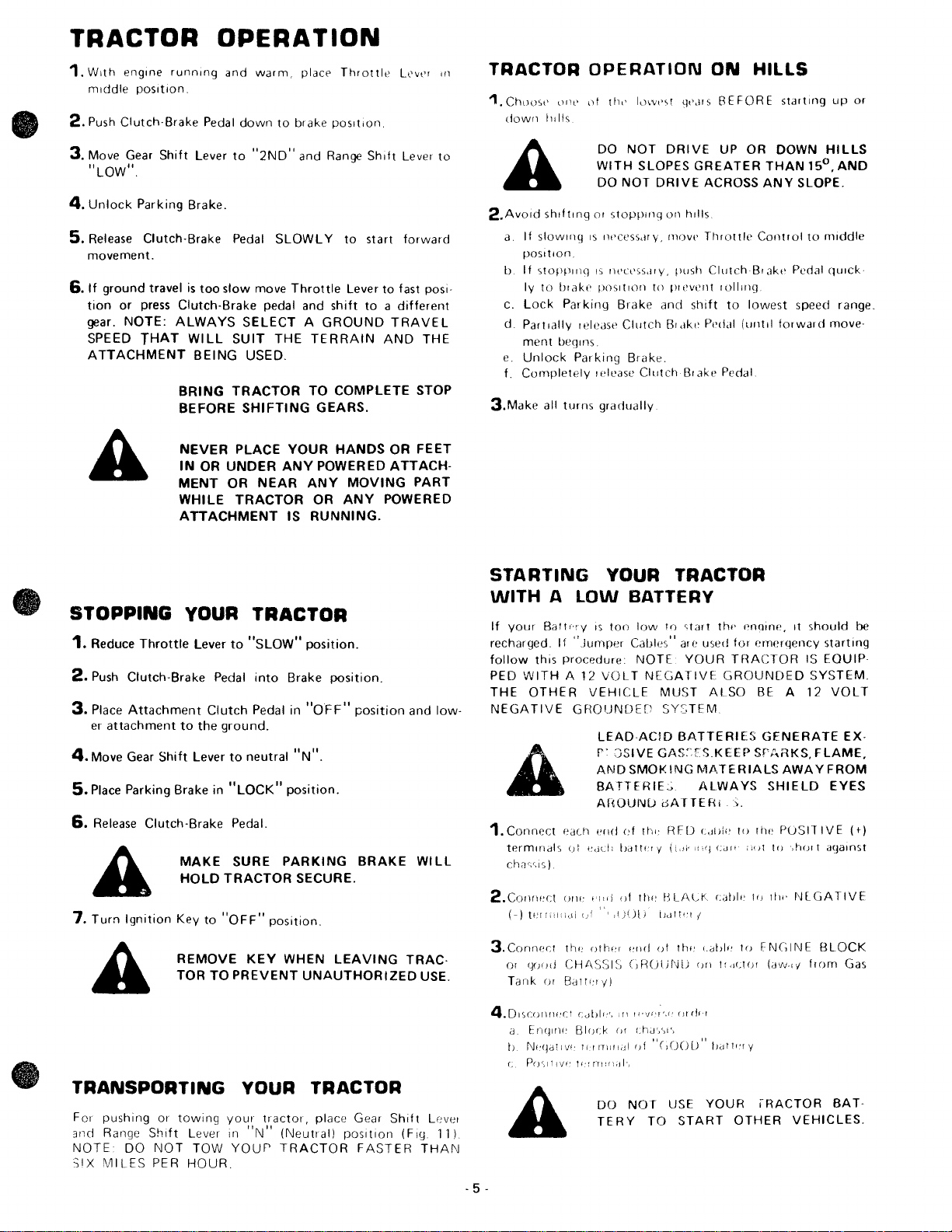
BRING
MENT
and
warm,
place
Pedal
down
to
brake
Lever
to
"2ND"
Brake.
Brake Pedal SLOW L Y
is
too
slow
SELECT A GROUND
WILL
SUIT
BEING
BEFORE
NEVER
IN
WHILE
ATTACHMENT
OR
USED.
TRACTOR
SHIFTING
PLACE
UNDER
OR
TRACTOR
move
Throttle
pedal and
THE
YOUR
ANY
NEAR
IS
and Range
Throttle
position
to
Lever
shift
TERRAIN
TO
COMPLETE
GEARS.
HANDS
POWERED
ANY
MOVING
OR
ANY
RUNNING.
Lev,'r
Shift
Lever
start
forward
to
fast posi·
to a different
TRAVEL
AND
THE
STOP
OR
FEET
ATTACH-
PART
POWERED
Ifl
to
TRACTOR
1.ChllD'C
down
(lIll'
11111s
A
2.Avold
3.Make
shifting
a
If
slOWing IS Ilt'CeSsdry,
POSition
b.
If
stoPPlIlq
to
bl
begrns.
all
ake
Parking
turns
Iy
c.
Lock
d.
Partially
ment
e.
Unlock
f.
Completely
OPERATION
elf
tilt'
ic)Wt,q
DO
NOT
WITH
SLOPES
DO
NOT
DRIVE
or
stoPPing on hills
IS
IH'Cl'SSdIY,
POSit
Ion
to
Brake
and
leleasp
Clutch
Parking
Brake.
lelease
gradually
Clutch
qt'.HS
DRIVE
GREATER
ACROSS
move
Throttle
push
pi
event
shift
Bldke
P"ddl
Blake Pedal
ON
HILLS
BEFORE
UP
OR
THAN
ANY
Control
ClutchBlak,'
lolling
to
lowest
(until
starting
DOWN
15°,
SLOPE.
to
middle
Pedal qUick·
speed range.
forward
up
or
HILLS
AND
move·
STOPPING
1.
Reduce
2.
Push
3.
Place
er
4.
Move Gear
5.
Place Parking Brake in
6.
Clutch·Brake
Attachment
attachment
Release
Throttle
Shift
Clutch·
A
7.
Turn
Ignition
A
YOUR
Lever
Pedal
Clutch
to
the
ground.
Lever
Brake Pedal.
MAKE
HOLD
TRACTOR
Key
to
"OFF"
REMOVE
TOR
TO
TRACTOR
to
"SLOW"
into
Brake
Pedal in
to
neutral
"LOCK"
SURE
PREVENT
position.
KEY
position.
PARKING
WHEN
position.
position.
"OFF"
"N".
SECURE.
UNAUTHORIZED
position
BRAKE
LEAVING
and
low·
WILL
TRAC·
USE.
STARTING
WITH A
If
your
recharged.
follow
PED
WITH
THE
OTHER
NEGATIVE
1. Connect
termlllais
Chilc,c,IS)
2.ColHwct
(-)
tfi[
3.ConrWCI
01
(¥Jod CHI\SSI:J
Tank
4.D,scorHH'ct
a Enqll1l: BII)r:K
h
NI'QdlIVI'
c
P(J(,lfl\)I't;'frllU:dl'J
lOW
BafU'ry
If
"Jumper
this procedure
A
GROUNDEr'
eacll
0\
(J/II:
:cii'
tlw
or
Battl:ty)
cdblf",
YOUR TRACTOR
BATTERY
IS
too
low
It)
qart
Cables" are
12
VOLT
VEHICLE
LEAD
r'JSIVE
AND
SMOK!NG
BATTERIE;;.
AflOUNu
"[Id
(,I
"del:
batt!:1 y
Illd
of
",
,/JUl)
oth'"
"I\d
(JRUl)NU
H1
ti"J!'r',f'
IJI
Jlllnilidl
f)f
NOTE
NEGATIVE:
ACID
thl:
tl1I:
cha',)I',
"C)()U[)"
u'>ed
YOUR
MUST
SYSTEM
GAS~ES.KEEP
of\TTERI>.
tJellt"1
of
ALSO
BATTERIES
MATERIALS
ALWAYS
RED
C,Ii)["
(l,'i'
lliq
HLALK
I
till:
cilblf!
on
()t(jf.!
th
..
enQlne, It should
for emergency
TRACTOR
GROUNDED
BE
GENERATE
Srr,RKS,FLAME.
SHIELD
to
the
Cdlt
:''it
II)
cahl"
II)
III!'
to
FNCliNE
fldUOI
halTl'IY
(aw"i
starting
IS
EOUIP·
SYSTEM.
A
12
VOLT
EX·
AWAYFROM
EYES
P()SIT
IVE
',hOI t iHJalnst
NlGATIVE
BLOCK
from
be
(t)
Gas
TRANSPORTING
For
3nei
NOTE
SIX
pushing
Range
MILES
DO
or
Shift
NOT
PER
towing
Lever in
TOW
HOUR.
YOUR TRACTOR
your
tractor,
"N"
Your
place Gear
(Neutral)
TRACTOR
position
FASTER
Shift
(Fig
Level
11)
THAN
-
5-
A
DO
TERY
NOT
TO
USE
START
YOUR
OTHER
IRACTOR
VEHICLES.
BAT·

SI XT Y
HAND
....----::=:=:-
HOUR : ..
I';,
---==
~ilil'
-
---..
--...:::::-
00
J/ /
x~.:>->-----HOURHAND
~~~~----~~-SYSTEM
INDICATOR
MAINTENANCE
To
keep
your
tractor
runnlllg better. longer;
uSing
service
Vice
Hour Meter IF,q 14) on the traclClr dash.
The Service
traclOr operation.
mark
Hand on the Inner dial,
operation. The System Indicator moves visibly when the
Ignition
operational.
the follOWing Maintenan
Hour
' Meter records the
Read
Indicating
Key
one hour
is
in the
DISCONNECT
PREVENT
FORE
JUSTMENT
REPAIR
the Hour Hand on the
of
operation. Read the
eac
h mark indicating
"ON"
position,
SPARK
ACCIDENTAL
MAKING
.
ANY
(EXCEPT
perform
ce
Schedul~
number
outer
sixty
indicating
PLUG
STARTING
INSPECTION,
CARBURETOR'
necessary
and the
of
hours
dial; each
Sixty
Hour
hours
the system
WIRES
Ser-
of
of
TO
BE·
AD·
OR
FIGUR
E 15
FIGURE 16
FIRST
1.CHECK
A
tion.
considerably
the
a.
b.
c. Move Flat Idler in frame slot 1/4 inch
d.
A
2.CHANGE
b.
~
HOURS:
V·BELTTENSION
new
V-Belt may stretch
If
Clutch·Brake Pedal, in drive
to
the
V-Belt
is
out
of
Secure Clutch-Brake pedal in brake
V-Belt
tension) by tieing
Hold
Nut
on inside
Bolt.
up
(to
loosen) V-Belt tension. Tighten
Release
mately
NOTE:
BELT
MOVEMENT
OLE
V·BELTS.
Changing
break-in residue
Note: Be
when
a.
Drain Oil
Cap.
Refill
(SC,
10W30
treme
SE). Capacity
FILL.
Clutch-Brake Pedal.
vertical position .
CHECK
NOT
SING
FOR
LONGER V-BELT
TENSIONED
POSITION,
changing
(Fig. 16) and catch Oil in a suitable container. Replace
SO
ENGINE
Oil
after
careful
with
Engine
or
SE)
(SC,
cold
WITH
which
oil.
Oil
SO
(below
is
after
the
first
few
position
front
or
rear
of
the vertical position,
adjustment and must be re·t
position
to
front
axle.
of
Flat Idler and loosen
down
Bolt
It
should
return
TO
MAKE
SURE
TRACTOR
START
CLUTCH·BRAKE
AND
the
not
Engine warm. Unscrew
Oil.
or SE)
3 -
WITHOUT
PROPERLY.
THROTTLE
ALWAYS
OIL
first
two
might
be
to
allow
(Fig. 17). In summer
In
winter
or
lOW40
OOF.)
use
112
pints. NOTE:
FULLY
PEDAl.
LIFE,
START
CONTROL
REPLACE
hours
will
damaging
dirt
to
(below
(SC,
S.A.E.
enter the Engine
320F.)
5W20
ALWAYS
SO
DO
hours
to
of
opera·
(Fig.
151.
ensioned.
(relaxing
Flat
Idler
(to tighten),
.
to
approxi-
DOES
DEPRES·
KEEP
TRACTOR
IN
WITH
help eliminate
your
Oil
use
or
NOT
MID·
SEARS
Engine.
Drain
Cap
S.A.E .
use S.A.E.
SE).
In
(SC, SO.
OVE
is
30
ex-
or
R·
CUT-
AWAY
VIEW
1 i
1
FIGURE
..
______________________
18 : :::-_-_- ;
:,1
--1J
r-lr
\1
1
.
.
' "
-
_-_-_-_
A-"'VENT
: -
~
~
:.
:!.
~
l:
n
-
~ _' j AI! Screen and Guard
CAP
BATTERY
TUBE
BCAElTlTERY
• .
FREQUENTLY:
1.
CHECK
a.
b. Keep Battery and Terminals clean. Refer
c.
d. Keep
e.
2.CHECK
Tir
3_
CLEAN
6-
and c
BATTERY
Electrolyte so
e
ven
with
tilled
wat
Keep Battery bolts tight.
ope
n.
Recha
rge
electro
TIRE
e pressure in
AIR
haff
lution
level in
bottoms
er
Vent Caps
SLOWLY
lyt
e falls below 1.225.
SCREEN
to prevent Engi
of
if
necessary. NOTE : DO
tight
at
PRESSURE
front
and rear Tires should
(F
tubes in cells (Fig . 18).
and small
3 amperes
ig 21) must
ne
each
damage
Battery
Cell should be
NOT
OVERFILL
Vent
holes in
if
specific gravity
be
be
kept free
from
Add
dis-
to
page
10.
caps
of
12
pounds.
of dirt
overheating.

EVERY
1.
CHECK
0
HOURS:
ENGINE
DO
WITH
OIL
NOT
LEVEL
CHECK
ENGINE
ENGINE
RUNNING
====;>~
OIL
LEVEL
.
STEERING
=
SECTOR
ARM
FITTING
GEAR
AND
GREASE
FRONT
PIVOT
AXLE
Several
Level
clean,
Oil Level.
reached.
winter
lOW40
S.A.E. 5W20
FILL.
2.
LUBRICATE
There
Using a
Extreme
able
at
3.01L
Place
move
a.
Idler
--
--
--
--
b.
Front
PIVOT
minutes
with
push
In
(below
(SC,
are
Grease
your
several
against
Bearing (Fig. 15)
Remove
Remove
Move Idler
posed
Return
Retainer
Axle
after
Tractor
it
down
If
necessary,
summer
320F.) use
SD
or
(SC, SO
STEERING
six
Grease
Gun,
Pressure
loeal
POINTS
drops
each
other,
Plastic
Retainer
Shaft.
Idler
Sp'ring
Pivot (Fig. 19)
stopping
on
level
ground.
ticj1t for a few
add
use
S.A.E.
S.A
.E.
SE).
In
extreme
or
SE).
AND
Fittings
give
of
Cap
and
and
each
Service
SAE
30
especially:
.
Spring
Shaft
Shaft
and
reposition
Lubricating
Sears
Engtn e , check Engine
Wipe
dipstick
seconds,
Oil untit
30
10W30
NOTE:
FRONTWHEELS
on
Grease
Grease
Center).
Oil
from
outward
to
original
remove
"FULL"
(SC, SD
cold
your
at
Idler
or
SE) Oil.
(SC,
SD
(below
OOF.) use
DO
NOT
Tractor
Fitting
Amdex No. 1 (Avail-
points
Cap.
Shaft.
and
position,
two
where
lubricate
(Fig. 17)
and
rea d
mark
or
SE)
OVER
(Fig.
shots
parts
replace
ad
is
In
or
·
19).
of
ex-
STEERING
BElLCRANK
GREASE
FITTING
FRONT
SPINDLE
GREASE
(LEFT & RIGHT)
FITTING
~-----
WING
AIR
COVER
FOAM
PRE-CLEANER
~_-PAPER
AIR
ELEMENT
FIGURE
NUT
FILTER
FILTER
19
EVERY~HOURS:
(EVERY
IN
1.CLEAN
a,
b. Clean
c. Wash
d.
e.
f.
g. Re-Assemble Air
2.CLEAN
Air
to
Screen
dirt,
3.CHANGE
The
operation
in the hot Oil Refer
15
VERY
DUSTY
AIR
Unscrew
Paper
ping
Element
Foam
Rinse,
oughly
Coat
with
knead
Check
dirty.
NOTE
REMOVED.
AIR
Screen
prevent
and
chaff,
best
HOURS
Wing
Air
dust
squeeze
.
to
distribute
Papel Air
NEVER
and
Engine
Guard
stubborn
ENGINE
time
when all
IF
CONDITIONS)
FILTER & FOAM
Nut
Filter
Element
from
Paper Air
on
a flat
Pre· Cleaner in
(rather
three
tabl
Filter
RUN
SCREEN
Guard
damage
and
dried
OIL
to
chanye
dirt
to
OPERATING
PRE-CLEANER
(Fig.
20)
to
remove
and
Foam
Pre-Cleaner.
Filter Ele
surface
detergent
than
twist)
esp
oons
evenly,
Fil~~r
(Fig.
and
Element.
and
ENGINE
21)
from
clean
with
gum
Engi ne
and
fOI elgn
page 6. - 7 -
ment
.
and
and
allow
of
S.A.E.
squeeze
Replace if excessively
re-position
WITH AIR
must
allow
overheating. Remove
a wi re
and
fibers
ad
IS at the end of a
materi al
Air
Filter
by
gently
water
to
30
Engine Oit,
out
on
CL[ANER
free-flow
brush
.
IS
Cover,
tap
.
dry
thor-
excess .
Tractor.
of
to
remove
da
suspend,'"
-
air
Air
y~
..
------------
---------
FIGU RE
21
..

EVERY
1.
CLEAN
Re
mov
(Fig
2.CHECK
a.
Block
Remove
h. Remove F,llel Plug (Fig
s
Mot
c. Check Pre:sure Relief Valve
top
pull
d.
Reposition
~@
ENGINE
e any dust,
22)
to
TRANSAXLE
up
hould
be even
or
Oi
(Fig
. 26).
ed
out
HOURS:
COOLING
dirt
iJr
event Engine damage fr
Rear A xle
le
ft rear
I I f necessary .
by
wheel.
with
It
han e
wheel
sho
!.
Secure
FINS
01 011
OIL
secure
23)
Fill
er
uld
sprrng
with
by
from
EnlJlne Cooling Fins
LEVEL
ly
or
use
removing
from
Transaxl
Plug threads.
locat
ed
completely
E·Ring.
om
overheating
a Tractor
E·Ring.
Add
on
R.H.
e.
all
S.A.E.
side near
closed
.
Jack.
Level
30
when
TRANSAXLE
FILLER
PLUG
EVERvTIOOOO
1.
CLEAN
Wire brush
reset gap at .025
they
show
2.CHECK
Replace Points
a.
Remove
ing
Mark
b. Remove
Pulley
on
er
1/4
c.
Remove Breaker
and
d.
Replace Points.
e.
Using
between
Gauge.
CLEAN
other
gap
f. Replace Break er
and
3.LUBRICATE
a.
Move
and
b. Coat Ball
c.
Reposition
HOURS:
SPARK
BREAKER
(Fig
.
gear cover aligns
lift
accurately
Air
Steering
PLUGS
carbon
deposits
signs
. 24).
(Fig.
turn
off
an
adjustment
Rubber
inch.
of
if
they
Air
Intake
This
Spark Plugs
15)
clockwise
to
ensure
Bo)<
to
remove.
if
Allen
Wrench,
Points
. Measure
NOTE: MAKE
AND
FREE
adjusts
Intake Hose.
BALL
Boots to expo
Link
Joints
with
Rubber
foulino
POINTS
necessary.
or
JOINTS
are
Box
(Fig. 28).
AND
RESET
from
(Fig.
or
pitted
Hose
that
provides
and
Belt
by
with
mark
points
Cover (F ig. 22)
adjust
Point
SURE
OF
GREASE,
alignment
Engine
Cover, Spark Plugs and Cables
Silicone Spray
Boot
s.
GAP
Spark Plug Electrodes
25). Replace Spark Plugs
electrode
or
connects
an
hand
are
Timing.
se
burned.
access
Guard
until
on
flywheel.
fully
open.
by
Set Screw
Gap
with a Flat
FEELER
OIL,
is
necessary.
Ball
Joints
Lubricant.
erosion.
to
Blower
to
view
and
turn
0
21
BTC
Turn
loosening Screw
for
GAUGE
OR
Setting
on
Hous·
Timing
Engine
mark
anoth·
.021
Feeler
DIRT.
lie
and
if
inch
IS
No
point
Hods
FIGURE
..
_________
25
ii~;.
___________
l.H
. SIDE
EVERV~UJ
1.
REPLACE
Refer
to
2.REPLACE
Refer
to
EVERY
CHANGE
a.
Block
ft Rea
Le
b.
DI ain Tr ansax Ie Oil
catchIng a ll In
c Re
fill
Transaxle
Capac
ity
Transaxl e, r iq. 26, I:l
axl
e to
C1
Check
..
.
[ IUSI'll wht'n pu
8.
(' R,'pos,tl()ll
HOURS:
PAPER
paQe
BREAKER
step
LDffiOO
TRANSAXLE
up
Rear
r Wheel
IS 5 qu,vts.
fill
mOle qui
Pres
sule Reli ef Valve. It should
\yht't"
AI
R FI L
7.
2,
above.
TER
POINTS
HOURS:
01
L
Axle
securely or
by
removing
by
rernoving Drain Plug (F ig. 26) and
sUi
table contarner. Replace
with
S.A.E.
Pressure Relief Valve
se
t)
may
ckly.
ll
ed a
li
t
iJy
S"
'Cll't' with E·R,ng .
hand and released .
ELEMENT
use a Tractor
E·Ring.
30 (SC,
be
held
Jack. Remove
Drain
SO
or
SE)
Motor
(R.H.
open
to
allow
spring co:T1pletely
PluQ.
Oil.
side
Trans·
of

AS NEEDED:
1.
REPLACE
If
fuel
replacement
a.
With
as
b. Place
A
2.TOE·IN
If
any parts
replaced,
a.
Loosen Jam Nuts (Fig. 28) at each end
justment
b.
Adjust
from
c.
Tighten
allel
proper
IN-LINE
filter
is
clogged,
is
required.
Engine
removed
new
ADJUSTMENT
(180
from
Fuel
BE
LEAKS
PROPER
In
Front
Tie Rod
Sleeves.
both
Tie Rods
10
to
Jam Nuts,
0
)
Front
Wheel
cool,
SURE
10
to
FUEL
obstructing
remove
both
Filter
in
THERE
AND
POSITION
Axle
1/8
making
each
Toe·in
or
so
other.
adjustment
ends
position
THAT
mches
FILTER
fuel
flow
to
carburetor,
and
plug
Fuel
Line
Sections
of
Fuel
Filter
(Fig.
in
Fuel
Line.
ARE
NO
FUEL
FUEL
LINE
IN
HOSE
Steering Mechanism are being
IS
required.
that
Tie Rod JOints measure
from
sure Tie Rod
This
and steering
of
center
adjustment
operation.
LINE
IS
CLAMPS.
Tie Rod Ad
to
Joints
are par·
secures
IN
center.
27).
3.BRAKE
If
Iy
then
a. Loosen Jam
b.
4.PARKING
If
justment
a.
b. Place Parking Brake Lever
c.
d.
e.
5.CARBURETOR
If
buretor
a.
b.
c.
d. Make
G.
RE·TENSION
It
page
ADJUSTMENT
Clutch·Brake
4 inches
brake
clockwise
until
Clutch·Brake
Tighten
Parking Brake
Loosen Parking Brake Hex Nuts (Fig. 29).
Hold
first
Hex
Release
.
turns
Tighten
Engine lacks
may need
Main
quire
wise, closing finger
wise 1 .
Turn
finger
one
turn.
Start Engine and
Shift
..
Turn
Engine runs
begins
tween these extremes.
Throttle
justment.
slowest engine speed
tion.
may
be
6).
Pedal (Fig. 29) has more
of
travel
from
adjustment
Nut
(from
in
Jam
Nut
against
BRAKE
is
necessary.
Clutch·8rake
Clutch·Brake
more agamst Bushing.
second Hex
Fuel (High Speed) Screw (Fig. 30)
adjustment.
Idle
tight
final
Lever
occasionally
ADJUSTMENT
will
Nut
finger
ADJUSTMENT
power
adjustment.
1/2
turns.
Adjusting
ON
L
adjustments
in
Neutral
Idle
Adjusting
"rough"
to
miss.
Stop
If
resetting
V·BEL
Screw (Fig. 30) should
vertical
is
necessary.
(Fig. 29) in
front
of
Pedal regains 4 inches
not
Pedal
tight
Nut
or
If
tight
Needle (Fig. 30)
Y,
allow
Return
T
tractor)
Turnbuckle.
hold
in
in
brake
against Bushing.
Pedal and
against first Hex
does
resetting
ON
L
and then
to
with
position
Needle
then
Screw
IS
necessary,
that
IleCeSSdlY
than
to
full
order
to
turn
one
tractor,
locked
not
will
Parking
position.
position
turn
first
idle
properly,
is
necessary,
Y,
then
turn
clockwise,
turn
counterclockwl::.e
warm
for
Engine
.
running
counterclockwise
clockwise
to a point
set
allow
smooth
to
Ie tellslOIl
approximate
brake
position
turnbuckle
turn
at a time
of
travel.
Brake ad·
and
tighten
Hex
Nut
Nut.
the Car·
snould
not
turn
clock·
counterclock·
closing
five
minutes.
and Gear
until
Engine
midway
not
require ad·
to
obtain
accelera-
Vhl!lt
two
reo
until
be-
the
(SI'(,
FIGURE
28
CHFCK
NOT
SING
TO
MAKE
SURE
START
CLUTCH-BRAKE
WITHOUT
TRACTOR
FULL Y DEPRES
PEDAL.
DOES
STOP
SCRf'W
 Loading...