

Sears 917.255561,Craftsman 917.255561 Owner's Manual
SEA/R $
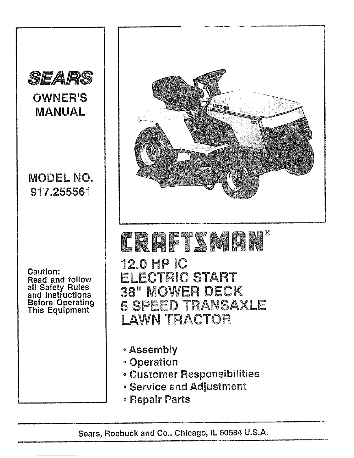
OWNER'S
MANUAL
Caution:
Read and follow
all Safety Rules
and lnstruct=ons
Before Operating
This Equipment
®
12o0HP WC
ELECTRIC START
38" MOWER DECK
5 SPESD TRANSAXLE
LAWN TRACTOR
°Assembly
oOperation
• Customer Responsibilities
oService and Adjustment
oRepair Parts
mlH,
, , H,_,M I I" I' _U,'_
Sears, Roebuck and Co., Chicago, IL 60684 U.S.A.
i , i i ii m ,,i

SAFETY RULES
Safe Operation Practices for Ride-On Mowers
IMPORTANT: THIS CUTTING MACHINE ISCAPABLE OF AMPUTATING HANDS AND FEET AND THROWING OBJECTS.
FA_LURE TO OBSERVE THE FOLLOWING SAFETY INSTRUCTIONS COULD RESULT IN SERIOUS iNJU RY OR DEATH,
I. GENERAL OPERATION
• Read, understand, and follow ail instructions in the manual
and on the machine before starting.
. Only allow responsible adults, who are familiar with the
instructions, to operate the machine,
• Clear the area of objects such as rocks, toys, wire, etc,
which could be picked up and thrown by the blade.
Be sure the area is clear of other people before mowing, Stop
machine if anyone enters the area+
Never carry passengers.
• Do not mow in reverse unfess absolutely necessary Always
look down and behind before and while backing.
= Be aware of the mower discharge direction and do not point
it at anyone, Do not operate the mower without either the
entire grass catcher or the guard in place.
. Stow down before turning
Never leave a running machine unattended., Always turn off
blades, set parking brake, stop engine, and remove keys
before dismounting.
. Turn off blades when not mowing,
• Stop engine before removing grass catcher or unclogging
chute
Mow only in daylight or good artificial lighL
• Do not operaie the machine while under the influence of
alcohol or drugs..
Watch for traffic when operating near or crossing roadways.+
Usa extra care when loading or unloading the machine into
a trailer or truck
1L SLOPE OPERATION
Slopes are a major factor related to loss-of-control and tipover
accidents, which can result in severe injury or death,, All slopes
require extra caution, if you cannot back up the slope or if you feel
uneasy on it, do not mow it,
DO:
Mow up and down slopes, not across+
Remove obstacles such as rocks, tree limbs, etc..
Watch for holes, ruts, or bumps Uneven terrain could
overturn the machine, Taft grass can hide obstacles.
Use slow speed. Choose a low gear so that you will not have
to stop or shift while on the slope
• Follow the manufacturer's recommendations for wheel
weights or counterweights to improve stabifity+
Use extra care with grass catchers or other attachments
These can change the stability of the machine,
Keep aElmovement on the slopes sfowand gradual Do not
make sudden changes in speed or direction.
• Avoid starting or stopping on a slope,, If tires lose traction,
disengage the blades and proceed slowly straight down the
slope,
DO NOT:
• Do not turn on slopes unless necessary, and then, turn slowly
and gradually downhill, if possible
• Do not mow near drop-offs, ditches, or embankments, The
mower could suddenly turn over if a wheel is over the edge
of a cliff or ditch, or if an edge caves in
• Do not mow on wet grass, Reduced traction could cause
sliding.
• Do not try to stabilize the machine by putting your foot on the
ground°
• Do not use grass catcher on steep slopes,
III. CHILDREN
Tragic accidents can occur if the operator is not alert to the
presence of children. Children are often attracted tothe machine
and the mowing activity Never assume that children wilt remain
where you last saw them,
Keep children out of the mowing area and under the watchful
care of another responsible adult.
• Be alert and turn machine off if children enter the area.
• Before and when backing, look behind and down for small
children,
• Never carry children, They may fall off and be seriously
injured or interfere with safe machine operation.
• Never allow children to operate the machine.
. Use extra care when approaching blind corners, shrubs,
trees, or other objects that may obscure vision_
IV. SERVICE
• Use extra care in handling gasoline and other fuels, They are
flammable and vapors are explosive.
Use only an approved container.
Never remove gas cap or add fuel with the engine
running Allow engine to cool before refueling, Do not
smoke
Never refuel the machine indoors.
Never store the machine or fuel container inside where
there is an open flame, such as a water heater,
Never run a machine inside a closed area
Keep nuts and bolts, especially blade attachment bolts, light
and keep equipment in good condition,,
Never tamper with safety devices, Check their proper
operation regularly
• Keep machine free of grass, leaves, or other debris build-up+
Clean oil or fuel spillage Allow machine to cool before
storing.
• Stop and inspect the equipment if you strike an object.
Repair, if necessary, before restarting,
Never make adjustments or repairs with the engine running.
• Grass catcher components are subject to wear, damage, and
deterioration, which could expose moving parts or allow
objects to be thrown, Frequently check components and
replace with manufacturer's recommended parts, when nec-
essary,
• Mower biades are sharp and can cut+ Wrap the blade(s) or
wear gloves, and use extra caution when servicing them,,
• Check brake operation frequently. Adjust and service as
required.
Look for this symbol to point out impor-
tant safety precautions. It means
CAUTION!!! BECOME ALERT!!! YOUR
SAFETY IS INVOLVED.
CAUTION: Always disconnect spark
plug wire and place wire where it cannot
contact spark plug In order to prevent
accidental starting when setting up,
transporting, adjusting or making
repairs.
2

CONGRATULATIONS on your purchase of a Sears
tractor, tt has been designed, engineered and manufac-
tured to give you the best possible dependability and
performance,
Should you experience any problem you cannot easily
remedy, please contact )/our nearest Sears Service
Center/DepartmenL We nave competent, well-trained
technicians and the proper tools to service or repair this
tractor.
Please read and retain this manual The instructions will
enable you to assemble and maintain your tractor prop-
efly, Always observe the "SAFETY RLJLES"_
MODEL
NUMBER 917255561
SERIAL
NUMBER
DATE OF PURCHAS E
THE MODELAND SERIAL NUMBERS WILL BE FOUND
ON A PLATE UNDER THE SEAT.
YOU SHOULD RECORD BOTH SERIAL NUMBER AND
DATE OF PURCHASE AND KEEP IN A SAFE PLACE
FOR FUTURE REFERENCE,
=RODUCT SPECIFICATIONS
HORSEPOWER: 12.0
GASOLINE CAPACITY: 5 QUARTS
UNLEADED REGULAR
OIL (3.0 PINTS): SAE 30 (Above 32°F)
5W-30(Below 32°F)
SPARK PLUG (GAP_030IN.): CHAMPION RJ-19LM
STD361458
VALVE CLEARANCE: INTAKE .005 - °007IN o
EXHAUST 009 _o011IN
GROUND SPEED: FORWARD
1st 1.1(_ MPH
2nd 2.00 MPH
3rd 3.00 MPH
4th 4.20 MPH
5th 500 MPH
REVERSE: 1.50 MPH
TIRE PRESSURE: FRONT: 14 PSI
REAR: 10 PSt
CHARGING SYSTEM: 3 AMPS BATTERY
5 AMPS HEADLIGHTS
BLADE BOLT TORQUE: 30-35 FT, LBS,
MAINTENANCE AGREEMENT
A Sears Maintenance Agreement is available on this trac-
tor. Contact your nearest Sears store for details.
CUSTOMER RESPONSIBILITIES
* Read and observe the safety rules.
o Follow a regular schedule in maintaining, caring for and
using your tractor°
, Follow the instructions under "Customer Responsibili-
ties" and "Storage" sections of this manual.
, iiiinll ,i n ,11,1,1111
WARNING: This tractor is equipped with an internal
combustion engine and should not be used on or near any
un mproved forest-covered, brush-covered or grass-cov-
ered land unless the engine's exhaust system is equipped
with a spark attester meeting applicable local or state taws
(if any). If a spark arrester is used, it should be maintained
in effective working order by the operator.
In the state of California the above is required by law
(Section 4442 of the California Public Resources Code).
Other states may have similar laws, Federal laws apply on
federal lands, A spark arrester for the muffler is available
through your nearest Sears Authorized Service Center
(See the REPAIR PARTS section of this manual)
i iHll u,iH, i IlllHHHI
LIMITED TWO YEAR WARRANTY ON ELECTRIC START RIDING EQj;?MENT
For two (2) years from the date of purchase, if this riding equipment is maintained, lubricated and tuned uo according to the
instructions in the owner's manual, Sears will repair or replace, free of charge, any parts found to be d,-_e:';',_ in material or
workmanship.
This Warranty does not cover:
, Expendable itemswhich become worn during normal use, such as blades, spark plugs, aircteanersand belts
• Tire replacement or repair caused by punctures from outside objects, such as nails,thorns, stumps, or glass.
• Repairsnecessary because of operator abuse,negligence,improper storage or accident or thefailure to maintain the
equipmentaccording tothe instructions contained in the owner's manual.
o Ridingequipment used for commercial or rentalpurposes
LIMITED 90 DAY WARRANTY ON BATTERY
For90 days from date of purchase, ifany battery inciuded with this riding equipment proves defective in material orworkmanship
and our testing determinesthe battery will not holda charge,Sears will replacethe battery at no charge
WARRANTY SERVICE IS AVAILABLE BY RETURNING THE RIDING EQUIPMENT TO THE NEAREST SEARS SERVICE
CENTER/DEPARTMENT INTHE UNITED STATES.
This Warranty gives you specific legal rights,and you may also have other rights which may varyfrom state to state
SEARS, ROEBUCK AND CQ, D/731CR-W, SEARS TOWER, CHICAGO, ILLINOIS 60684
IH N,,
3

TABLE OF CONTENTS
SAFETY RULES ............................................................ 2
PRODUCT SPECIFICATIONS ....................................... 3
CUSTOMER RESPONSIBILITIES ..................... 3, 14-17
WARRANTY ................................................................... 3
TABLE OF CONTENTS ................................................. 4
INDEX ............................................................................. 4
TRACTOR ACCESSORIES ........................................... 5
ASSEMBLY ................................................................ 7"9
OPERATION ........................................................... 10-t3
MAINTENANCE SCH EDULE ...................................... 14
SERVICE AND ADJUSTMENTS ............................ 18-23
STORAGE .................................................................... 24
TROUBLESHOOTING ............................................ 25-26
REPAIR PARTS - TRACTOR ................................. 28.43
REPAIR PARTS - ENGINE ..................................... 44-48
PARTS ORDERING/SERVICE ................... BACK _GE
INDEX
A
Accessories ........................................................5
Adjustments:
Brake ............................................. 20
Carburetor ....................................... 23
Mower
Front-To-Back ............................19
Side-To-Side ................................19
Throttle Control Cabie .......................23
Air Filter, Engine .................................. 17
Air Screen, Engine ................ .................. 17
Assembly ..........................................................7-9
B
Battery:
Charging ..................................................8
Cleaning ..............................................16
Installation ............................................9
Levels .............................................8,16
Preparation ..........................................8
Starting with Weak Battery ........... 21
Storage .................................................24
Terminals ........................................ 16
Belt:
Motion Drive
Removal/Replacement ........... 20
Mower Blade Drive
RemovaVReplacement ...............20
Blade:
Sharpening ...........................................15
Replacement ......................................15
Brake Adjustment ................................... 20
C
Carburetor Adjustment ...........................24
Controls, Tractor ......................................10
Customer Responsibilities .................14-17
Engine:
Air Filter ..................................... 17
Air Filter Foam Pre-Oleaner .... 17
Air Screen, Engine .................... 17
Battery ......................................... 16
Cooling Fins, Engine ...................I7
Engine Oil ....................................t6
Fuel Filter .................................... 17
Spark Plugs ................................... 17
Tractor:
Blade ...............................................15
Lubrication Chart ..................... 14
Maintenance Schedule ............ 14
Tire Care ..............................8,15,21
Cutting Height, Mower .......................... ll
E
Electrical:
interlocks and Relays .....................22
Schematic ...................................... 27
Wiring Diagram .....................................28
Engine:
Air Filter ............................................t 7
Air Filter Foam Pre-Oleaner ..........17
Air Screen ...............................................17
Cooling Fins, Engine ...........................17
Oil Change ........................................!6
Oil Level .............................................12,16
Oil Type .................................................16
Preparation ........................................12
Repair Parts ..........................................44-48
Starting ..................................................13
Storage ................................................24
F
Filter:
Air Filter ............................................... 1 7
Air Filter Foam Pre-Cleaner ...........17
Fuel .........................................................17
Fuel:
Type ...................................................12
Storage ....................................................24
Fuse ..............................................................22
H
Headlights ............................................... 22
Hood Removal/Installation ....................22
L
Leveling Mower Deck .............................19
Lubrication:
Chart ........................................... ........ 14
M
Maintenance Schedule ..........................14
Mower:
Adjustment, Front-to-Back .............19
Adjustment, Side-to-Side ............ ! 9
Blade Sharpening .............. :.......... 15
Blade Replacement ........................15
Cutting Height ............. ...................... 11
Installation ...................................... 18
Operation .........................................12
Removal ........................................... 18
Mowing Tips ........................................... t 3
Muffler ...................................................... t 7
Spark Arrester .................................3,38
O
Oil:
Cold Weather Conditions ..... 12,16
Engine ........................................... 16
Storage ........................................... 24
4
Operation ................................................10-13
Operating Mower ..................................... 12
Options:
Accessories ...........................................5
Spark Arrestel: ..............................3,38
P
Parking Brake .........................................10-t 1
Parts Bag ................................................. 6
Parts, ReplacemenlJRepair ............ 28-43
Product Specifications ...................................3
R
Repair Parts ........................................28-43
S
Safety Rules .....................................................2
Seat .................... ........................................... 8
Service and Adjustments ................ 18-23
Carburetor ...................................._.......23
Fuse ......................................................22
Hood Removal/Installation .......... 22
Motion Drive Belt
Removal/Replacement ...............20
Mower Blade Drive Belt
Removal/Replacement ........... 20
Mower Adjustment
Front- to-Back ......................... 19
Side-to-Side .............................. 19
Mower Installation .......................... 18
Mower Removal .............................. 18
Tire C_ire ...................................8,15,21
Slope Guide Sheet ..................................51
Spark Plugs ............................................ 17
Specifications .......... :..................................3
Starting the Engine .......................... 12-13
Steering Wheel .........................................7,21
Stopping the Tractor ...................................11
Storage ................................................... 24
T
Throttle Control Cable
Adjustment ..........................................23
Tires...............................................................8,15,21
Trouble Shooting Chart .....................25-26
Transaxle:
Repair Parts ............................. 42-43
W
Warranty .................................................... 3
Wiring Diagram ...................................... 28
Wiring Schematic ................................... 27
ACCE$$ORUSS AND ATTACH ENT$
........ i ii ii1,1, ,,, i
i , ,, ,i,,,i,,,i
Those accessories and attachments were available when the tractor was purchased. They are also available at most Soars retail outlets,
catalog and service centers. Most Sears stores can order these ffems for you when you provide the model number of your tractor.
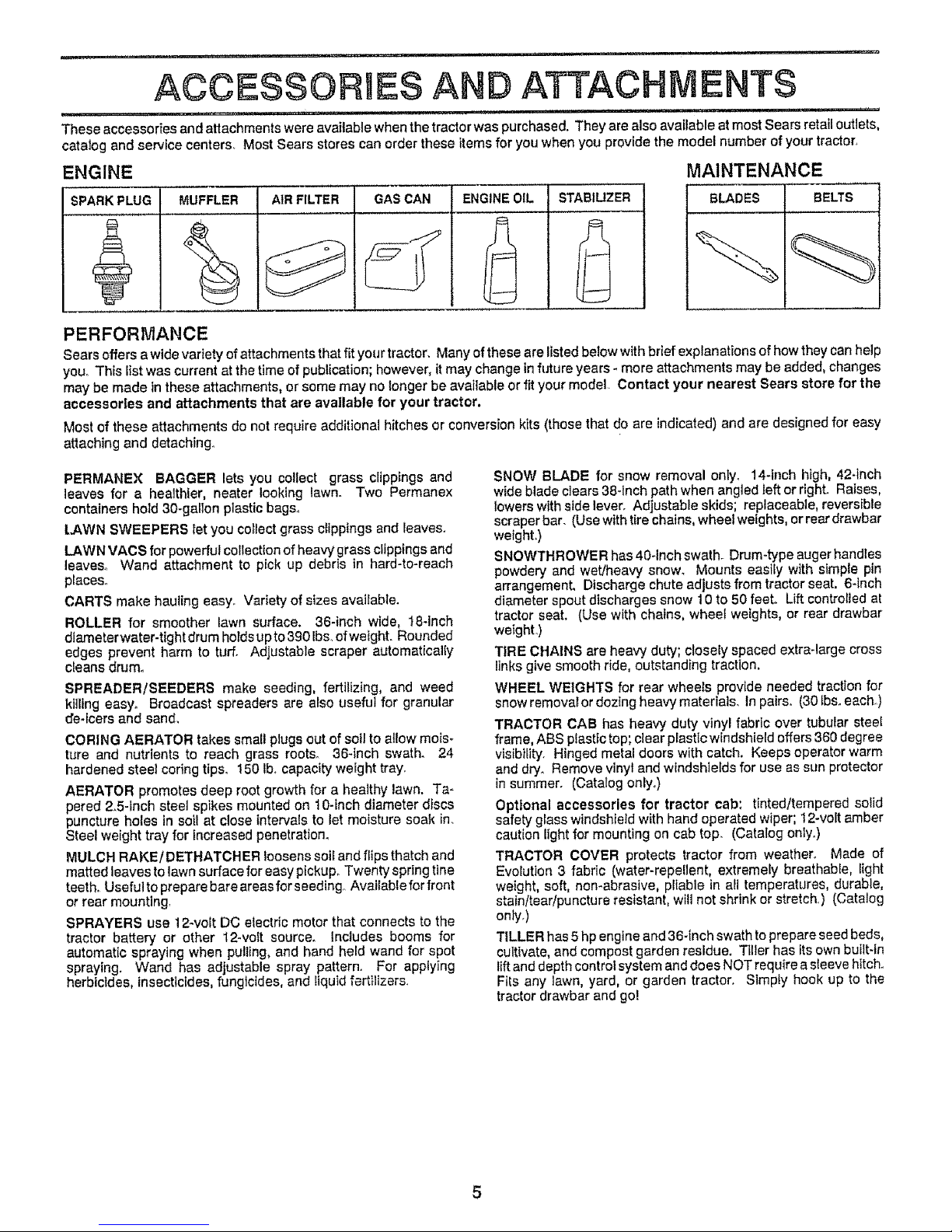
ENGINE MAINTENANCE
SPARK PLUG MUFFLER AIR FILTER GAS CAN ENGINE OIL STABILIZER
BLADES BELTS
PERFORMANCE
Sears offers a wide variety of attachments that fit your tractor. Many ofthese are listed below with brief explanations of how they can help
you° This list was current at the time of publication; however, it may change in future years - more attachments may be added, changes
may be made in these attachments, or some may no longer be available or fit your model Contact your nearest Sears store for the
accessories and attachments that are available for your tractor.
Most of these attachments do not require additional hitches or conversion kits (those that do are indicated) and are designed for easy
attaching and detaching°
PERMANEX BAGGER lets you collect grass clippings and
leaves for a healthier, neater looking lawn. Two Permanex
containers hold 30-gallon plastic bags°
LAWN SWEEPERS let you collect grass clippings and leaves.
LAWN VACS for powerful collection of heavy grass clippings and
leaves° Wand attachment to pick up debris in hard-to-reach
places°
CARTS make hauling easy_ Variety of sizes avaifable.
ROLLER for smoother lawn surface. 36-inch wide, 18-inch
diameterwater-tightdrum hoIdsupto390Ibs_ofwefght. Rounded
edges prevent harm to turf° Adjustable scraper automatical{y
cleans drum°
SPREADER/SEEDERS make seeding, fertilizing, and weed
killing easy_ Broadcast spreaders are a_so useful for granular
cre.icers and sand,
CORING AERATOR takes sma{l plugs out of soil to allow mois-
ture and nutrients to reach grass roots_ 36-inch swath. 24
hardened steel coring ttps_ t50 Ib, capacity weight tray.
AERATOR promotes deep root growth for a healthy lawn. Ta-
pered 2.5-inch steel spikes mounted on 10-inch diameter discs
puncture holes in soil at close Intervals to let moisture soak in
Steel weight tray for increased penetration_
MULCH RAKE/DETHATCHER loosens soii and flipsthatch and
matted leaves to lawn surface for easy pickup. Twenty spring tine
teeth. Usefultopreparebareareasfarseeding AvaiIablefor front
or rear mounting
SPRAYERS use 12-volt DC electric motor that connects to the
tractor battery er other 12-voft source. Includes booms for
automatic spraying when pulling, and hand held wand for spot
spraying. Wand has adjustable spray pattern. For applying
herbicides, insecticides, fungicides, and Iiquid fertilizers.
SNOW BLADE for snow removal only. 14-Inch high, 42_Inch
wide blade clears 38-1nch path when angled left or right. Raises,
towers with side leven Adjustable skids; replaceable, reversible
scraper bar. (Use with tire chains, wheel weights, er rear drawbar
weight,)
SNOWTHROWER has 40-Inch swath. Drum-type auger handtes
powdery and wet!heavy snow_ Mounts easily with simple pin
arrangemenL Discharge chute adjusts from tractor seat, 6-inch
diameter spout discharges snow 10 to 50 feet. Lift controlled at
tractor seat. (Use with chains, wheel weights, or rear drawbar
weighL)
TIRE CHAINS are heavy duty; closely spaced extra-large cross
links give smooth ride, outstanding traction.
WHEEL WEIGHTS for rear wheeIs provide needed traction for
snow removat or dozing heavy materials. In pairs° (30 lbs. each.)
TRACTOR CAB has heavy duty vinyl fabric over tubular steel
frame, ABS plastic top; clear plastic windshield offers 360 degree
visibility. Hinged metal doors with catch. Keeps operator warm
and dry_ Remove vinyl and windshields for use as sun protector
in summer. (Catalog only,)
Optional accessories for tractor cab: tinted/tempered solid
safety glass windshield with hand operated wiper; 12-volt amber
caution light for mounting on cab top. (Catalog only.)
TRACTOR COVER protects tractor from weather. Made of
Evolution 3 fabric (water-repellent, extremely breathable, light
weight, soft, non-abrasive, pliable in all temperatures, durable,
stain/tear/puncture resistant, will not shrink or stretch.) (Catalog
onty.)
TILLER has 5 hp engine and 36-inch swath to prepare seed beds,
cultivate, and compost garden residue. Tiller has its own built-in
lift and depth control system and does NOT require a sleeve hitch.
Fits any lawn, yard, or garden tractor. Slmply hook up to the
tractor drawbar and go!
.................... . .............. ,_,,,., ....... , ,. ,, ,, ,, ,..- ; ......
, ,,,,,,_,,,,_
CONTENTS OF HARDWARE PACK
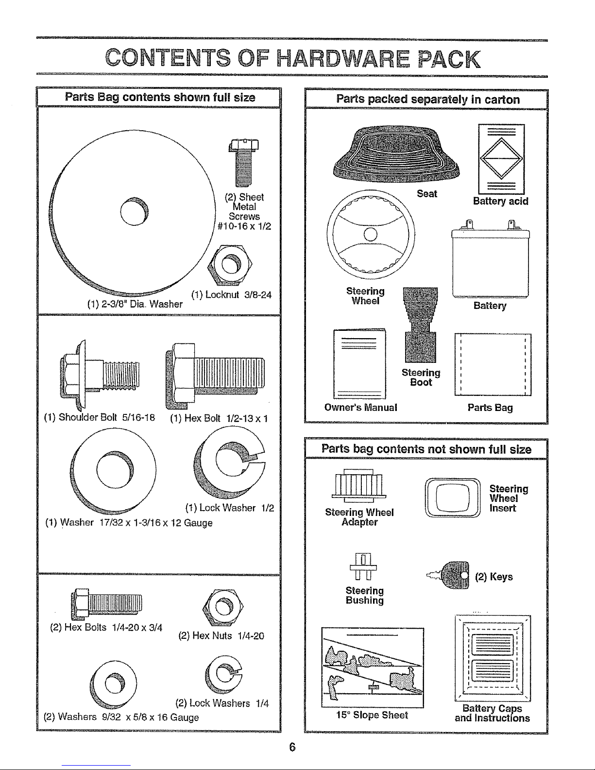
Parts Bag contents shown full size
......... ,,i,,,, i ,,, 1,1,,,,,i........... .
Sheet
112
©
i
(t) Lock Washer 1/2
(1) Shoulder Bolt 5/16-18 (!) Hex Bolt 1/2-13 x 1
@
(1) Washer 17/32 x '1-3/16x I2 Gauge
@
(2) Hex Nuts 114-20
(2) Hex Boits 1/4-20 x 3/4
G
(2) Lock Washers 1/4
(2) Washers 9/32 x 5/8 x 16 Gauge
Parts pa ked eparately in carton
,,, ,,,, ,...........
Steering
Wheel
Seat
Steering
Boot
O
Battery acid
Battery
t
Owner's Manual Parts Bag
, ,, ,.............. ,,, ,
Parts bag contents not shown full size
_[_ !_l Steering
' .... Wheel
Steering Wheel Insert
Adapter
Steering
Bushing
15 ° Slope Sheet
_(2) Keys
'_ ........ .j'
E €
I I
Battery Caps
and Instructions
6
i . ii,.i, i u ,,, i i n lUll,i, nl,,ll
ASSEM LY
L I IIU i I !1 .... i1,, I , IIII III IIIII , IIIII
Your new tractor has been assembled at the factory with except on of those parts left unassembled for shippfng purposes.
To ensure safe and proper operation of your tractor all parts and hardware you assemble must be tightened securely. Use
the correct tools as necessary to insure their proper tightness.
TOOLS REQUIRED FOR ASSEMBLY
A socket wrench set will make assembly easier+ Standard
wrench sizes are listed,
(l) 5/16" wrench
(2) 7/16" wrenches
(1) 1/2" wrench
(l) 9/t6" wrench
3/4" wrench
Tire pressure gauge
Screwdriver
Utility knife
When right and left hand is mentioned in this manual, it
means when you are in the operating position (seated
behind the steering wheel).
TO REMOVE TRACTOR FROM CARTON
UNPACK CARTON
• Remove all accessible loose parts and parts cartons
from carton (See page 6)°
• Cut along lines on carton, from top to bottom, all four
corners of carton and lay panels flaL
• Check for any additional loose parts or cartons and
remove.
BEFORE ROLLING TRACTOR OFF SKID
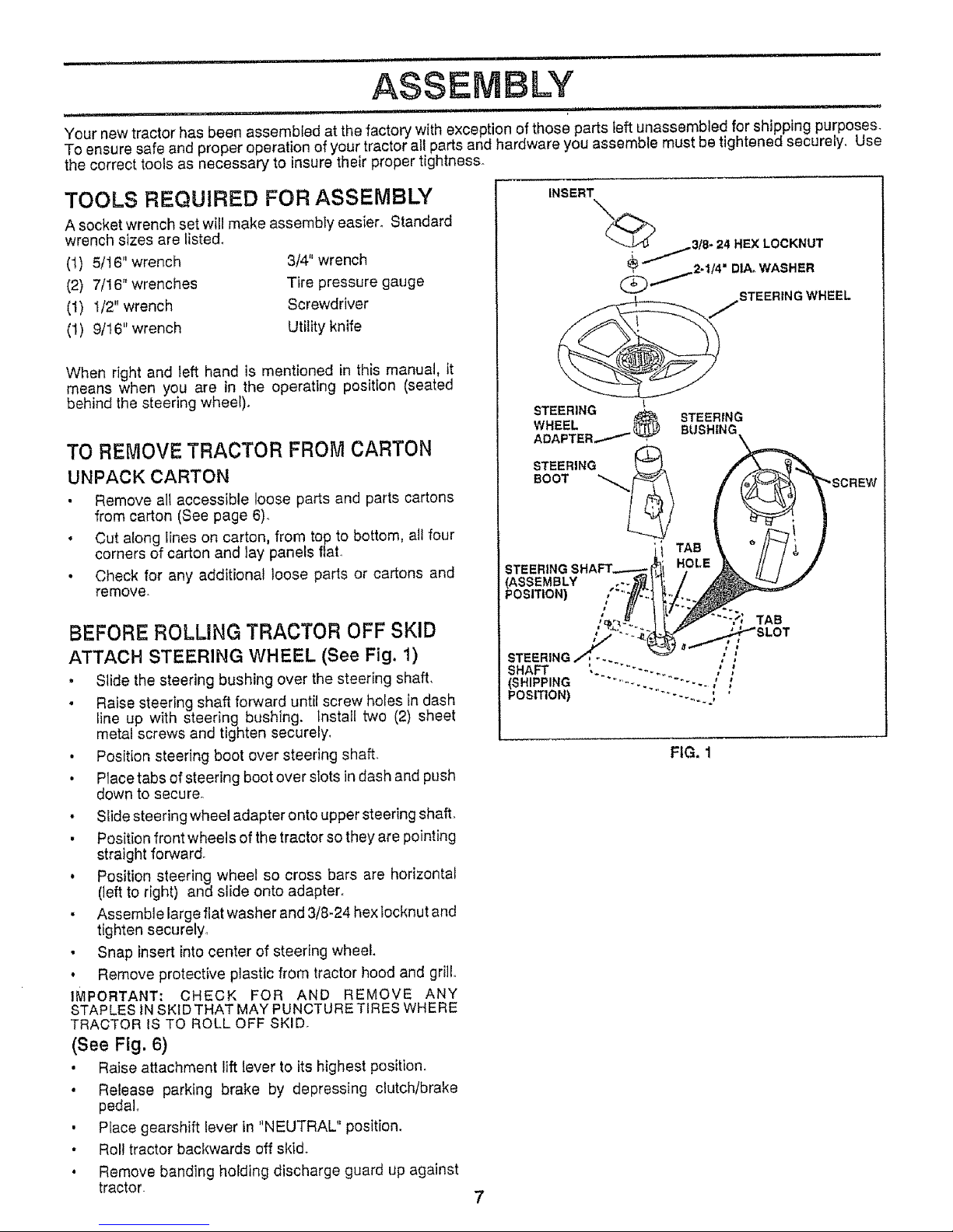
ATTACH STEERING WHEEL (See Fig, 1)
+ Slide the steering bushing over the steering shaft,
° Raise steering shaft forward until screw holes in dash
line up with steering bushing. Install two (2) sheet
metal screws and tighten securely,
, Position steering boot over steering shall
• Place tabs of steering boot over slots in dash and push
down to secure°
• Slide steering wheel adapter onto upper steering shaft,
• Position front wheels of the tractor so they are pointing
straight forward.
• Position steering wheel so cross bars are horizontal
(]eft to right) and slide onto adapter.
• Assemble large flat washer and 3/8-24 hextocknut and
tighten securely,
• Snap insert into center of steering wheel.
• Remove protective plastic from tractor hood and grill,,
IMPORTANT: CHECK FOR AND REMOVE ANY
STAPLES tN SKID THAT MAY PUNCTURE TIRES WHERE
TRACTOR IS TO ROLL OFF SKID.
(See Ftg. 6)
• Raise attachment lift lever to its highest position.
• Release parking brake by depressing clutch/brake
pedal.
• Place gearshift lever in "NEUTRAL" position.
• Roll tractor backwards off skid.
, Remove banding holding discharge guard up against
tractor.
7
INSERT
"X._ 3t8- 24 HEX LOCKNUT
_2-114" DtA. WASHER
jSTEERING WHEEL
STEERING
WHEEL _ STEERING
ADAPTER,,_,_ BUSHING
STEERING i
BOOT _i
TAB
STEERING
(ASSEMBLY
POSITION) ":'?
FIG. 1
ASSE BLY
HOW TO SET UP YOUR TRACTOR
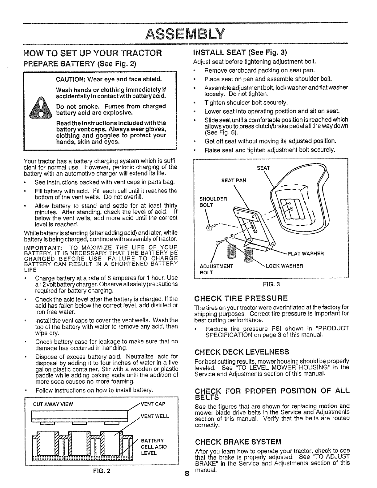
PREPARE BATTERY (See Fig. 2)
i llll i,. , i ,, i ,m i ,t=_,,,,
CAUTION: Wear eye and face shield,
Wash hands or clothing Immediately if
accldentallyln contact with battery actd.
Do not smoke. Fumes from charged
battery acld are explosive.
Read the Instructions Included with the
battery vent caps. Alwayswear gloves,
clothing and goggles to protect your
hands, skin and eyes.
Your tractor has a battery charging system which is suffi-
cient for normal use. However, periodic charging of the
battery with an automotive charger wili extend its life.
" See instructions packed with vent caps in parts bag.
, Fill battery with acid. Fill each cell until it reaches the
bottom of the vent we{Is. Do not overfill.
• Ailow battery to stand and settle for at least thirty
minutes. After standing, check the _evelof acid. If
below the vent wells, add more acid until the correct
level is reached.
While battery is standing (after adding acid) and later, while
battery isbeing charged, continue with assembly of tractor.
IMPORTANT: TO MAXiMiZE THE LIFE OF YOUR
BATTERY, IT IS NECESSARY THAT THE BATTERY BE
CHARGED BEFORE USE FAILURE TO CHARGE
BATTERY CAN RESULT {N A SHORTENED BATTERY
LiFE
• Charge battery at a rate of 6 amperes for 1 hour. Use
a 12volt battery charger. Observe all safety precautions
required for battery charging.
. Check the acid level after the battery is charged, Ifthe
acid has fallen below the correct level, add distilled or
iron free water.
. Install the vent caps to cover the vent weIIs. Wash the
top of the battery with water to remove any acid, then
wipe dry,
• Check battery case for leakage to make sure that no
damage has occurred in handling.
• Dispose of excess battery acid, Neutralize acid for
disposal by adding it to four inches of water in a five
gallon plastic container. Stir with a wooden or plastic
paddle white adding baking soda until the addition of
more soda causes no more foaming,
o Follow instructions on how to install battery.
CUTAWAYVIEW j VENTCAP
j w. W LL
_ BATTERY
t _ r-_ _ _ r_ _ r.,'J r_/f_t CELLAClD
INSTALL SEAT (See Fig. 3)
Adjust seat before tightening adjustment bolt.
° Remove cardboard packing on seat pan.
Place seat on pan and assemble shoulder bolt.
. Assemble adjustment bolt, lock washer and flat washer
loosely. Do not tighten.
• Tighten shoulder bolt securely.
, Lower seat into operating position and sit on seat.
. SIide seat until a comfortable position is reached which
aIIows you to press clutch/brake pedal all the way down
(See Fig. 6).
• Get off seat without moving its adjusted position.
, Raise seat and tighten adjustment bolt securely.
SEAT PAN
SHOULDER
BOLT
oFLAT WASHER
ADJUSTMENT " LOCK WASHER
BOLT
FIG, 3
CHECK TIRE PRESSURE
The tires on your tractor were overinflated at the factory for
shipping purposes. Correct tire pressure is important for
best cutting performance.
. Reduce tire pressure PSI shown in "PRODUCT
SPECIFICATION on page 3 of this manual.
CHECK DECK LEVELNESS
For best cutting results, mower housing should be properly
leveled. See "TO LEVEL MOWER HOUSING" in the
Service and Adjustments section of this manual.
CHECK FOR PROPER POSITION OF ALL
BELTS
See the figures that are shown for replacing motion and
mower blade drive belts in the Service and Adjustments
section of this manual. Verify that the belts are routed
correctly.
CHECK BRAKE SYSTEM
After you learn how to operate your tractor, check to see
that the brake is properly adjusted. See "TO ADJUST
BRAKE" in the Service and Adjustments section of this
manual
F1Go2 8

ASSEMBLY
iNSTALL BA3"TEF Y (See Figs. 4 & 5)
CAUTION: Do not short battery termi-
nals. Before installing battery, remove
metal bracelets, wristwatch bands,
rings, etc,
Positive terminal must be connected
first to prevent sparking from acciden-
tal grounding.
o Lift seat to raised position.
• Open battery box dOOrr
° Lower battery into battery box with battery terminals
toward front of tractor_
= Be sure battery drain tube is attached to battery box..
• First connect RED battery cable to positive (+) battery
terminal with hex bott, flat washer, lock washer and hex
nut as shown. Tighten securely
o Connect BLACK grounding cable to negative (-) bat-
tery terminal with remaining hex bolt, flat washer, lock
washer and hex nut. Tighten securely.
• Close battery box door_
Open battery box door for:
= Inspection for secure connections (to tighten hard-
ware).
o Inspection for corrosion.
• Testing battery.
o Jumping (if required).
o Periodic charging°
BATTERY
BOX DOOR
POSITIVE NEGATIVE
(RED)
CABLE CABLE
LOCK WASHER
HEX
BOLT
POSITIVE (+) TERMINAL NEGATIVE TERMINAL
FIG. 4
VENTCAPS
BEFORE YOU OPERATE AND ENJOY YOUR NEW
TRACTOR, WE WISH TO ASSURE THAT YOU RECEIVE
THE BES TPERFORMANCE AND SA TISFA C TION FROM
THIS QUALITY PRODUCT.
PLEASE REVIEW THE FOLL 0 WING CHECKLIST:
v" All assembly instructions have been completed.
v" No remaining loose parts in carton_
¢" Battery is properly prepared and charged_ (Minimum
1 hour at 6 amps)_
v" Seat is adjusted comfortably and tightened securely
v" All tires are properly inflated. (For shipping purposes,
the tires were over-inflated at the factory).
v" Be sure mower deck is properly leveled side-to-side/
front-to-rear for best cutting results.. (Tires must be
properly inflated for leveting).
v" Check mower and drive belts. Be surethey are routed
properly around pulleys and inside all belt keepers.
•/ Check wiring.. See that all connections are still secure
and wires are properly clamped.
WHILE LEARNING HOW TO USE YOUR TRACTOR, PAY
EXTRA A TTENTION TO THE FOLLOWING IMPORTANT
ITEMS:
#" Engine oil is at proper level,
V" Fuel tank is filled with fresh, clean, regular unleaded
gasoline.
J" Become familiar with all controls - their' location and
function° Operate them before you start the engine..
_" Be sure brake system is in safe operating condition.
i
OPERATION
KNOW YOUR TRACTOR
READ THIS OWNER'S MANUAL AND SAFETY RULES BEFORE OPERATING YOUR TRACTOR
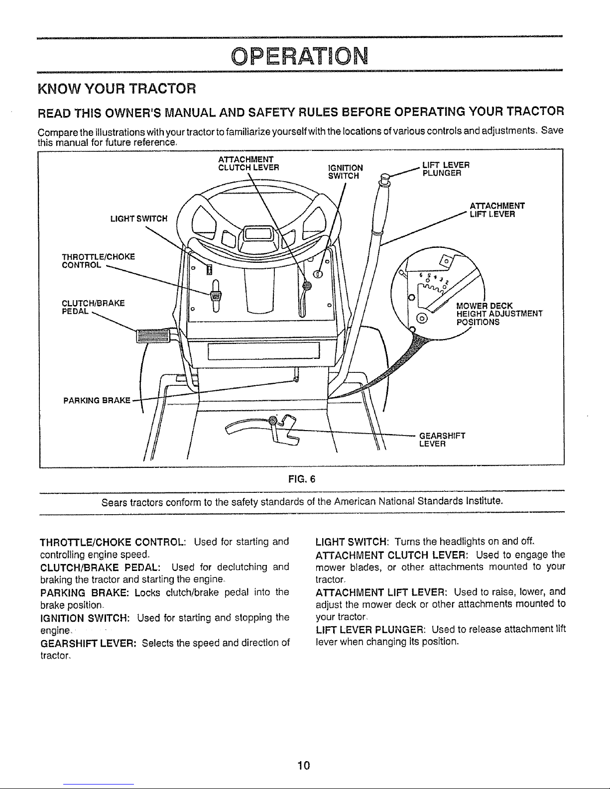
Compare the illustrationswith yourtractor to familiarize yourself with the locations ofvarious controls and adjustments, Save
this manual for future reference,
ATTACHMENT
CLUTCH LEVER
IGNITION LIFT LEVER
SWtTCH PLUNGER
LIGHT SWITCH
-.\
THROTTLE/CHOKE
CONTROL
ATTACHMENT
LIFT LEVER
CLUTCH/BRAKE
[ t
MOWER DECK
HEIGHT ADJUSTMENT
POSITIONS
PARKING
GEARSHIFT
LEVER
FIG. 6
Sears tractors conform to the safety standards of the American National Standards Institute°
THROTTLE/CHOKE CONTROL: Used for starting and
controlling engine speed.
CLUTCH/BRAKE PEDAL: Used for declutching and
braking the tractor and starting the engine.
PARKING BRAKE: Locks clutch/brake pedal into the
brake position.
IGNITION SWITCH: Used for starting and stopping the
engine_
GEARSHIFT LEVER: Selects the speed and direction of
tractor.
LIGHT SWITCH: Turns the headlights on and off.
ATTACHMENT CLUTCH LEVER: Used to engage the
mower blades, or other attachments mounted to your
tractor_
ATTACHMENT LIFT LEVER: Used to raise, lower, and
adjust the mower deck or other attachments mounted to
your tractor_
LIFT LEVER PLUNGER: Used to release attachment lift
lever when changing its position.
10
................... ............................... ,................ ' v,, i ...... _r
OPERATION
The operation of any tractor can result in foreign objects thrown into the eyes which can
result in severe eye damage. Always wear safety glasses or eye shields while operating
your tractor or performing any adjustments or repairs. We recommend wide vision safety
mask for over the spectacles or standard safety glasses, available at Sears Retail or
Catalog stores°
HOW TO USE YOUR TRACTOR
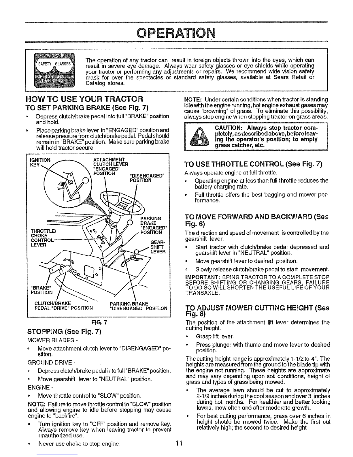
TO SET PARKING BRAKE (See Fig. 7)
o Depress clutch/brake pedal into full "BRAKE" position
and hold_
= Place parking brake lever in "ENGAG ED"position and
release pressure from clutclVbrakepedal. Pedalshould
remain in "BRAKE" position, Make sure parking brake
will hold tractor secure.
NOTE: Under certain conditions when tractor is standing
idle with the engine running, hot engine exhaust gases may
cause "browning" of grass. To eliminate this possibility,
always stop engine when stopping tractor on grass areas°
(_ CAUTION: Always stop tractor com-
pletely, as described above, before leav-
ing the operator's position; to empty
, grass catcher, etc. _........
IGNITION ATTACHMENT
KEY_ CLUTCH LEVER
"ENGAGED"
POSITION
"DISENGAGED"
POSITION
THRO'rrL_
CHOKE
CONTROL"
LEVER
PARKING
BRAKE
"ENGAGED"
GEAR-
SHIFT
LEVER
"BRAKE"
POSITION
/ \
CLUTCH/BRAKE PARKING BRAKE
PEDAL "DRIVE" POSITION "DISENGAGED" POSITION
FIG. 7
STOPPDNG (See Fig. 7)
MOWER BLADES -
. Move attachment clutch lever to "DISENGAGED" po-
sition,
GROUND DRIVE -
o Depress clutch/brake pedal into full "BRAKE" position.
o Move gearshift lever to "NEUTRAL" position_
ENGINE -
o Move throttle control to "SLOW" position.
NOTE: Failure to move throttle control to "SLOW" position
and allowing engine to idle before stopping may cause
engine to "backfire",
o Turn ignition key to "OFF" position and remove key.
Always remove key when leaving tractor to prevent
unauthorized use.
o Never use choke to stop engine.
11
TO USE THROTTLE CONTROL (See Fig. 7)
Always operate engine at full throttle.
o Operating engine at lessthan full throttle reduces the
battery charging rate.
o Full throttle offers the best bagging and mower per-
formance.
TO MOVE FORWARD AND BACKWARD (See
Fig. 6)
The direction and speed of movement iscontrolled by the
gearshift lever
• Start tractor with clutch/brake pedal depressed and
gearshift lever in "NEUTRAL" position°
° Move gearshift lever to desired position,
o Slowly release clutch/brake pedal to start movemenL
IMPORTANT: BRING TRACTOR TO A COMPLETE STOP
BEFORE SHIFTING OR CHANGING GEARS. FAILURE
TO DO SO WILL SHORTEN THE USEFUL LIFE OF YOUR
TRANSAXLE.
TO ADJUST MOWER CU'I-[ING HEIGHT (See
Fig.6)
The position of the attachment lift lever determines the
cutting height,
• Grasp lift lever,
° Press plunger with thumb and move lever to desired
position.,
The cutting height range is approximately 1-112 to 4'L The
heights are measured from the ground to tne b_adetip with
the engine not running° These heights are approximate
and may vary depending upon sob conditions, height of
grass and types of grass being mowed.
° The average lawn should be cut to approximately
2-1/2 inches during the cool season and over 3 inches
during hot months. For healthier and better looking
lawns, mow often and after moderate growth_
° For best cutting performance, grass over 6 inches in
height should be mowed twice, Make the first cut
relatively high; the second to desired height.
OPERATUON
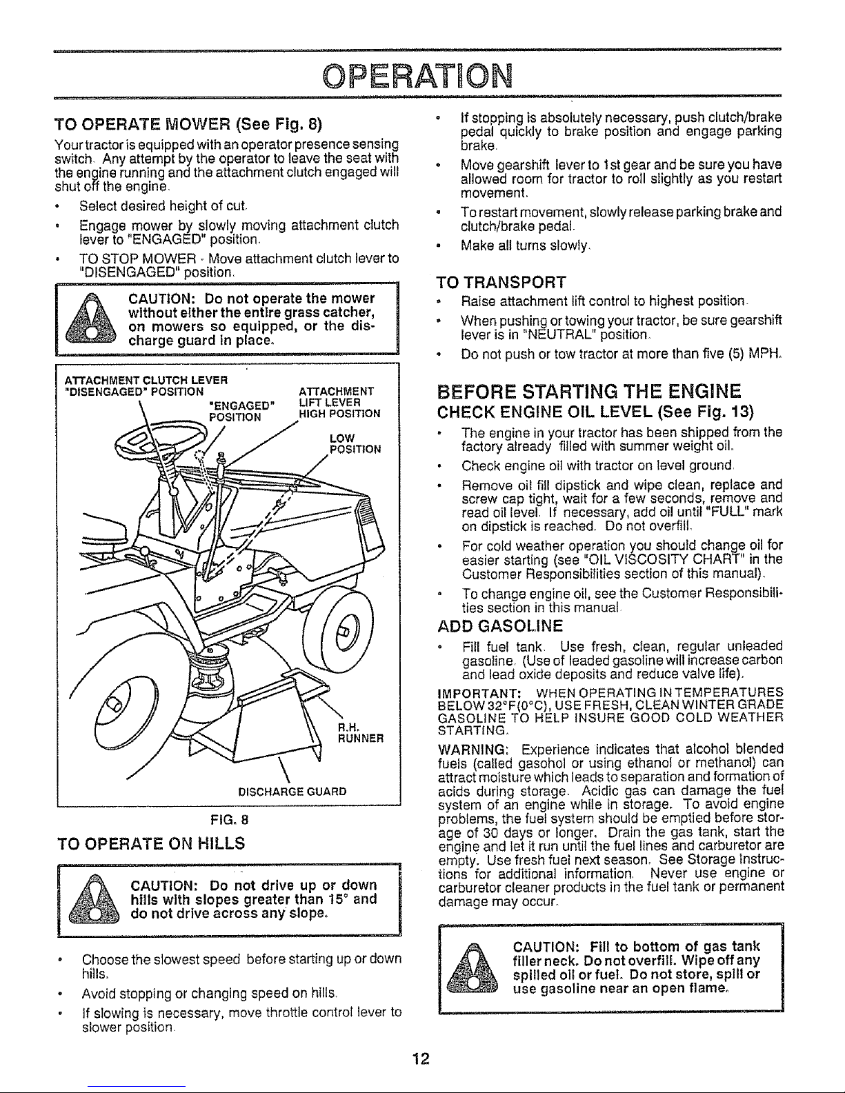
TO OPERATE MOWER (See Fig. 8) °
Your tractor is equipped with an operator presence sensing
switch. Any attempt by the operator to leave the seat with
the engine running and the attachment clutch engaged will °
shut off the engine.
• Select desired height of cut.
• Engage mower by slowly moving attachment cTutch
lever to 'ENGAGED position. .
• TO STOP MOWER - Move attachment clutch lever to
"DISENGAGED" position.
CAUTION: Do not operate the mower
without either the entire grass catcher,
on mowers so equipped, or the dis-
charge guard in place°
If stepping is absolutely necessary, push clutch/brake
pedal quickly to brake position and engage parking
brake.
Move gearshift lever to 1st gear and be sure you have
afiowed room for tractor to roil slightly as you restart
movement,
To restart movement, slowly release parking brake and
clutch/brake pedal.
Make all turns slowly.
TO TRANSPORT
. Raise attachment lift control to highest position.
° When pushing or towing your tractor, be sure gearshift
lever is in "NEUTRAL" position.
. Do not push or tow tractor at more than five (5) MPH,
ATTACHMENT CLUTCH LEVER
"DISENGAGED"POSITION
"ENGAGED"
POSITION
ATTACHMENT
LIFT LEVER
HIGH POSITION
LOW
POSITION
g.H_
RUNNER
DISCHARGE GUARD
FIG. 8
TO OPERATE ON HILLS
i , ,i,, ,,i............... II
CAUTION: Do not drive up or down
hills with elopes greater than !5 ° and
I
do not drive across any' slope.
° Choose the slowest speed before starting up or down
hills.
. Avoid stopping or changing speed on hills.
• if slowing is necessary, move throttle control lever to
slower position
BEFORE STARTING THE ENGINE
CHECK ENGINE OIL LEVEL (See Fig. 13)
The engine in your tractor has been shipped from the
factory already filled with summer weight oil,,
• Check engine oil with tractor on level ground,
- Remove oil fill dipstick and wipe clean, replace and
screw cap tight, wait for a few seconds, remove and
read oil level, If necessary, add oil until "FULL" mark
on dipstick is reached, Do not overfill.
° For cold weather operation you should change oil for
easier starting (see "OIL VISCOSITY CHART" in the
Customer Responsibilities section of this manual).
° To change engine oil, see the Customer Responsibili-
ties section in this manual
ADD GASOLINE
° Fill fuel tank. Use fresh, clean, regular unleaded
gasoline. (Use of leaded gasolinewill increase carbon
and lead oxide deposits and reduce valve life).
IMPORTANT: WHEN OPERATING IN TEMPERATURES
BELOW 32°F(0°C), USE FRESH, CLEAN WINTER GRADE
GASOLINE TO HELP INSURE GOOD COLD WEATHER
STARTING.
WARNING: Experience indicates that alcohol blended
fuels (catled gasohol or using ethanol or methanol) can
attract moisture which leads to separation and formation of
acids during storage. Acidic gas can damage the fuel
system of an engine while in storage. To avoid engine
problems, the fuel system should be emptied before stor-
age of 30 days or longer, Drain the gas tank, start the
engine and let it run until the fuel lines and carburetor are
empty. Use fresh fuel next season_ See Storage instruc-
tions for additional information. Never use engine or
carburetor cleaner products in the fuel tank or permanent
damage may occurA
, i iirl i
i_ AUTION: Fill to bottom of gas tank
filler neck. Do not overfill. Wipe off any
spilled oil or fuel Do not store, spill or
use gasoline near an open flame.
= ........
12
m,i .......................................... i i iiii i, ......................,I"JlJJlllLL I I,II,IllL
OPERATIO
TO START ENGINE (See Fig. 7) • Drive so that clippings are discharged onto the area
that has been cut. Have the cut area to the right of
When starting engine for the first time or if engine has the tractor, This will result in a more even distribu-
run out of fuel, it wilt take extra cranking time to move lion of clippings and more uniform cutting.
fuel from the tank to the engine_
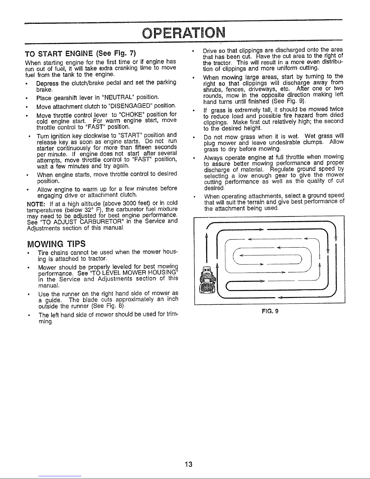
. When mowing large areas, start by turning to the
• Depress the clutch/brake pedal and set the parking right so that clippings will discharge away from
brake° shrubs, fences, driveways, etc. After one or two
• Place gearshift lever in "NEUTRAL" position° rounds, mow in the opposite direction making left
hand turns until finished (See Fig° 9).
. Move attachment clutch to "DISENGAGED" position,
• If grass is extremely tall, it should be mowed twice
• Move throttle control lever to "CHOKE" position for to reduce load and possible fire hazard from dried
cold engine start. For warm engine start, move clippings. Make first cut relatively high; the second
throttle control to "FAST" position, to the desired height.
• Turn ignition key clockwise to "START" position and • Do not mow grass when it is wet, Wet grass will
release key as soon as engine starts. Do not run plug mower and leave undesirable clumps,. Allow
starter continuously for more than fifteen seconds grass to dry before mowing_
per minute, If engine does not start after several
attempts, move throttle control to "FAST" position, • Always operate engine at full throttle when mewing
wait a few minutes and try again, to assure better mowing performance and proper
• When engine starts, move throttle control to desired discharge ef material. Regulate ground speed by
selecting a low enough gear to give the mower
position, cutting performance as well as the quality of cut
• Allow engine to warm up for a few minutes before desired.
engaging drive or attachment clutch. • When operating attachments, select a ground speed
NOTE: If at a high altitude (above 3000 feet) or in cold that wilt suit the terrain and give best performance of
temperatures (below 32 ° F), the carburetor fuel mixture the attachment being used.
may need to be adjusted for best engine performance.
See "TO ADJUST CARBURETOR' in the Service and
Adjustments section of this manual,
MOWING TiPS
° Tire chains cannot be used when the mower hous-
Ing is attached to tractor,
• Mower should be properly leveled for best mowing
performance. See "TO LEVEL MOWER HOUSING"
in the Service and Adjustments section of this
manual,
. Use the runner on the right hand side of mower as
a guide. The blade cuts approximately an inch
outside the runner (See Fig, 8).
• The left hand side of mower should be used for trim-
ming,
i., ....
FIG, 9
13
CUSTOMSR
, i
RESPONS LtT ES
.... = i , = n.............
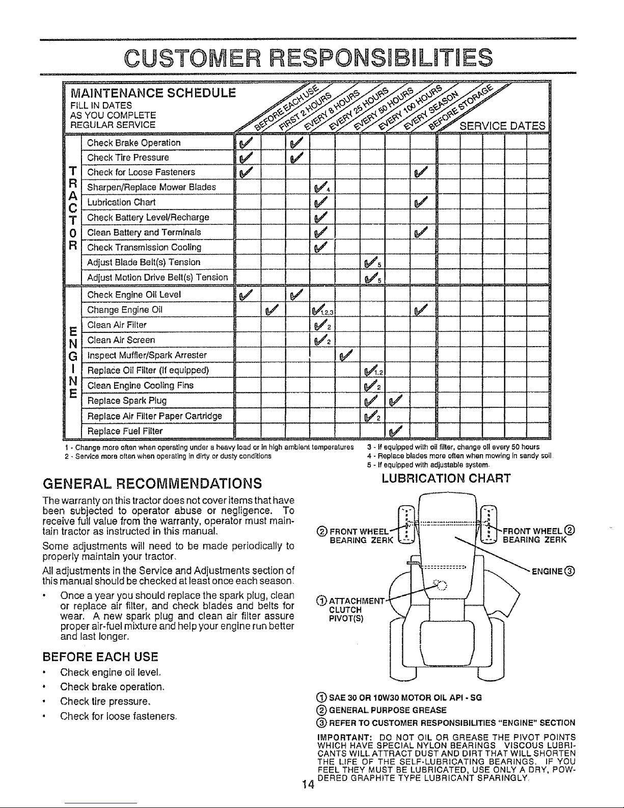
MAINTENANCE SCHEDULE
FiLL IN DATES
AS YOU COMPLETE
REGULAR SERVICE
Check BrakeOperation
Check Tire Pressure 6_
T Check for Loose Fasteners 64#
R Sharpen/Replace MowerBlades
Lubrication Chart
T Check Battery Level/Recharge
0 Clean Battery and Terminals
a CheckTransmisston Cooling
Adjust BIade Belt(s) Tension .............'
Adjust Motion Ddve Belt(s)Tension
Check Engine _OilLevel
Change Engine Oil
E Clean Air Filter
N CleanAir Screen..............
G inspectMuffler/SparkArrestor
J
SERVICE DATES
I
Replace Oit Filter (If equipped)
Clean Engine Cooling Fins
Replace Spark Plug
Replace Air Filter PaperCartridge
Replace Fuel Filter
; ; _ . =....
J
e"
v'2
e"
1 - Change more often when operating under e heavy load or in high ambient temperatures
2 - Service more often when operating In dirty or dusty conditions
GENERAL RECOMMENDATIONS
The warranty on this tractor does not cover items that have
been subjected to operator abuse or negligence. To
receive full value from the warranty, operator must main-
tain tractor as instructed in this manual,
Some adjustments will need to be made periodically to
property maintain your tractor.
All adjustments in the Service and Adjustments section of
this manual should be checked at least once each season.
• Once a year you should replace the spark plug, clean
or replace air filter, and check blades and belts for
wear. A new spark plug and clean air filter assure
proper air-fuel mixture and help your engine run better
and last longer.
3 - If equipped with oil filter, change oil every 50 hours
4 - Replace blades more oftenwhen mewing Insandy soil
S- tf equipped withadjustable system
LUBRICATION CHART
®
CLUTCH
P=VOT(S)
BEFORE EACH USE
• Check engine oil levelo
• Check brake operation°
• Check tire pressure,
• Check for loose fasteners.
(_ SAE 30 OR 10W30 MOTOR OIL APt -
SG
(_) GENERAL PURPOSE GREASE
® REFER TO CUSTOMER RESPONSIBILITIES "ENGINE" SECTION
IMPORTANT: DO NOT OIL OR GREASE THE PIVOT POINTS
WHICH HAVE SPECIAL NYLON BEARINGS VISCOUS LUBRI-
CANTS WILL ATTRACT DUST AND DIRT THAT WILL SHORTEN
THE LIFE OF THE SELF-LUBRICATING BEARINGS, IF YOU
FEEL THEY MUST BE LUBRICATED, USE ONLY A DRY, POW-
14 DERED GRAPHITE TYPE LUBRICANT SPARINGLY
L / "11nl I ' "1"""_ .............. i.!ll i .I.IlU,I .lUI,--'_ ......... I ' I
CUSTOMER RESPON IBILmTUES
am, ........................................ i in
TRACTOR
Always observe safety rules when performing any mainte-
nance.
BRAKE OPERATION
If tractor requires more than six (6)feet stopping distance
at high speed in highest gear, than brake must be adjusted.
(See "TO ADJUST BRAKE" in Service and Adjustments
section of this manua0_
TIRES
• Maintain proper air pressure in all tires (See "PROD-
UCT SPECIFICATIONS' on page 3 of this manual).
• Keep tires free of gasoline, oit,or insect control chemi-
cals which can harm rubber°
• Avoid stumps, stones, deep ruts, sharp objects and
other hazards that may cause tire damage.
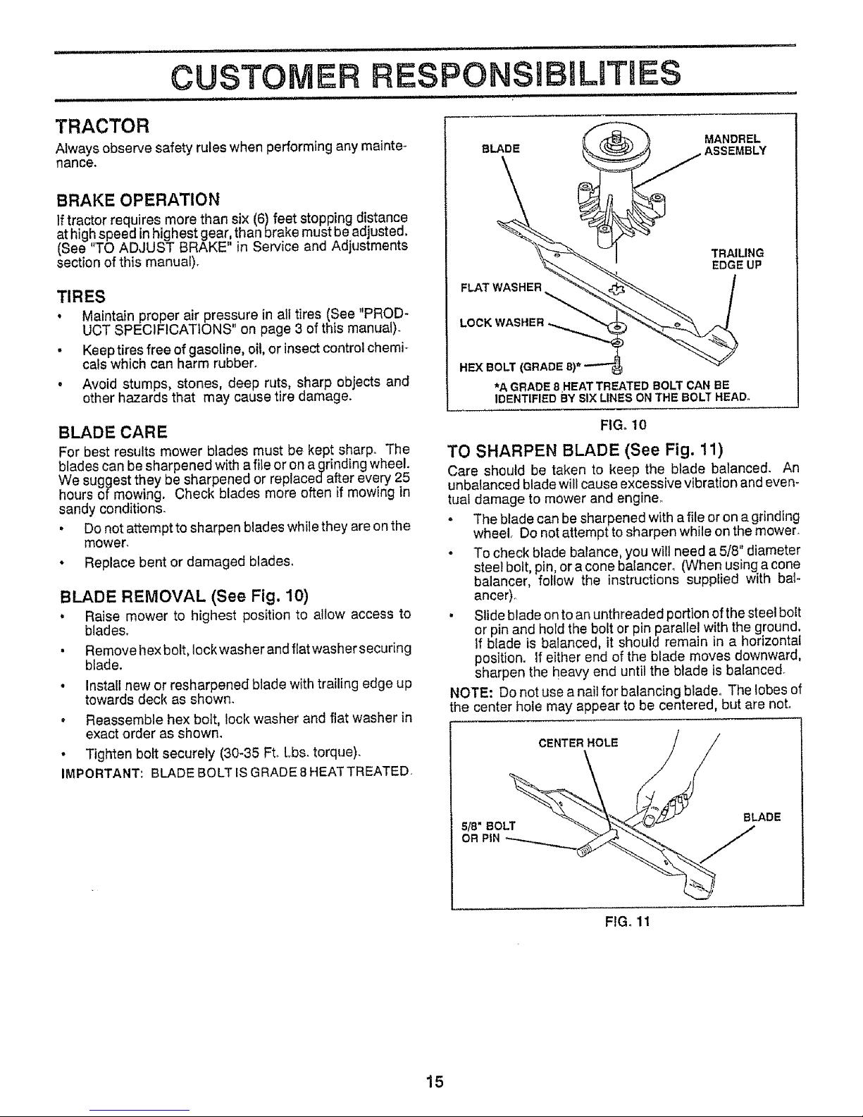
"_ MANDREL
BLA.DE _.______ _ . ASSEMBLY
_..._ _; EDGEUP
FLATWASHER -_'._ _ I
HEX BOLT (GRADE 8)* --"-"_;_
*A GRADE 8HEATTREATED BOLT CAN BE
IDENTIFIED BY SIX LINES ON THE BOLT HEAD°
BLADE CARE
For best results mower blades must be kept sharp. The
blades can be sharpened with a _e or on agrinding wheel.
We suggest they be sharpened or replacedafter every 25
hours of mowing. Check blades more often if mowing in
sandy conditions.
• Do not attempt to sharpen blades while they are on the
mower,
• Replace bent or damaged blades_
BLADE REMOVAL (See Fig. 10)
• Raise mower to highest position to allow access to
blades.
• Remove hex bolt, Iockwasher and flat washer securing
blade.
• Install new or resharpened blade with trailing edge up
towards deck as shown.
• Reassemble hex bolt, lock washer and flat washer in
exact order as shown.
• Tighten bolt securely (30-35 Ft. Lbs. torque),
IMPORTANT: BLADE BOLT IS GRADE 8 HEAT TREATED.
FIGot0
TO SHARPEN BLADE (See Fig. 11)
Care should be taken to keep the blade balanced. An
unbalanced blade will cause excessive vibration and even-
tual damage to mower and engine_
. The blade can be sharpened with a file or on a grinding
wheel. Do not attempt to sharpen while on the mower.
- To check blade balance, you wilt need a 5/8" diameter
steel bolt, pin, or a cone balancer. (When using a cone
balancer, follow the instructions supplied with bal-
ancer).
, SJideblade on to an unthreaded portion of the steel bolt
or pin and hold the bolt or pin parallel with the ground,
If blade is balanced, it should remain in a horizontal
position, if either end of the blade moves downward,
sharpen the heavy end until the blade is balanced.
NOTE: Do not use a nail for balancing blade. The lobes of
the center hole may appear to be centered, but are not.
CENTER HOLE
5/8" BOLT BLADE
OR PiN J
FIG. 11
15

¢USTO ER ESPONS BILITUE$
BATTERY (See Fig. 12)
Your unit has a battery charging system which is sufficient
for normal use. However, periodic charging of the battery
with an automotive charger will extend it's life.
• Acid solution level in each battery cell should be even
with bottoms ofvent wells. Add only distilled or iron free
water if necessary. Do not overfill.
• Keep battery and terminals clean.
• Keep battery bolts tight.
• Keep vent caps tight and small vent holes in caps open.
, Recharge at 6 amperes for 1 hour°
TO CLEAN BATTERY AND TERMINALS -
Corrosion and dirt on the battery and terminals can cause
the battery to "leak" power.
• Remove terminal guard.
• Disconnect BLACK battery cable first then RED bat-
tory cable and remove battery from tractor_
• Wash battery with solution of four tablespoons of
baking sodato one gatlon of watero Be careful notto get
the soda solution into the cel]s.
• Rinse the battery with plain water and dry°
, C1eanterminals and battery cable ends with wire brush
until bright.
" Coat terminals with grease or petroleum jelly.
• Reinstall battery (See "iNSTALL BATTERY" in the
Assembly section of this manual).
CUT AWAY VIEW CAP
WELL
CELL ACID
LEVEL
FIG. 12
V-BELTS
Check V-belts for deterioration and wear after 100 hours of
operation and replace if necessary° The belts are not
adjustable. Replace belts if they begin to slip from wear.
ENGINE
LUBRICATION
Only use high quality detergent o!1rated with API service
classification SG. Select the oil s SAE viscosity grade
according to your expected operating temperature.
I SAE VISCOSITY G_DES I,_o' o' , _o' _. 40. _0' , _,
"o .=c, -_'o" ._a" _" 1'o' 20" _'.. ,,o_
TEMPERATURE RAJ_GEA,NTICIPATEID BEFORE Nt_._'TOIL CHANGE
NOTE: Although multi-viscosity oils (5W30, 10W30, etc.
improve starting in cold weather, these multi-viscosity oils
will result in increased oil consumption when used aboe
32°C. Check your engine oil level more frequently to avoid
possible engine damage from running low on oil.
Change the oil after the first two hours of operation and
every 25 hours thereafter or at least once a year if the
tractor is not used for 25 hours in one year.
Check the crankcase oil level before starting the engine
and after each eight (8) hours of continuous use. Tighten
oil fill cap/dipstick securely each time you check the oil
level.
TO CHANGE ENGINE OIL (See Fig. 13)
Determine temperature range expected before oil change.
All oil must meet API service classification SG.
• Be sure tractor is on level surface.
• Oit will drain more freely when warm°
• Catch oil in a suitable container.
• Remove oil fill dipstick. Be carefut not to allow dirt to
enter the engine when changing oil.
• Remove drain plug
• After oil has drained completely, replace oil drain plug
and tighten securely.
• Refill engine with oil through oil fill dipstick tube. Pour
slowly. Do not overfill. For approximate capacity see
"PRODUCT SPECIFICATIONS" on page 3 of this
manual.
• Use gauge on oit fill dipstick for checking level. Be sure
dipstick cap is tightened securely for accurate reading°
Keep oil at "FULL" line on dipstick.
TRANSAXLE COOLING
Keep transaxte free from build-up of dirt and chaff which
can restrict cooling_
/
/
OIL FILL
OIL DRAIN PLUG
FIG. 13
16
 Loading...