

Page 1
..--------
I Sears I
OWNERS
MANUAL
..........
-----
~
-----'*
---------.
MODEL
917.253721
Read
Safe Operation
Instructi
and
NO
.
Caution:
Rules
Carefully
for
ons
GTV
16
TWIN
VARIDRIVE
GARDEN
TRACTOR
'
"-'
----------
Sears
Assembly
Installation
Operation
Repair
, Roebuck and Co., Chicago, Ill. 60684 U.S.A.·
Parts
Page 2
CONGRATU
16
GTV
and
manufactured
Sho
uld you
edy,
please
They
tools
and
Please read
you
to
Always observe
H.P.
cont
have
competent,
parts
and
assemble,
LATIONS
experience
Garden
to
act
to
service or
retain
operate
the
on
your
Tractor.
give
your nearest
well·trained
this
"RU
you
any
repair
manual.
and
LES
problem
FOR
It has
dependability
maintain
purchase
been
you cann
Sears,
Roebuck and
technicians
this
unit
The
instruction
SAFE
of
a Sears Varidrive
designed,
.
your Tractor
OPERATION".
engineered
and
performance.
ot easily
and
the
s will
rem·
Co. s
tore.
proper
enable
properly.
MODEL
NUMBER
SERIAL
NUMB
ER
THE
MODEL AND
BE
FOUND
ED
TO
{REFER
YOU
SHOULD
S
ERIAL
PLACE
FOR
______________________
___________
ON
THE
TO
THE
TOP
PAGE
RECORD
NUM
BERS
FUTURE REFERENCE
____________
SERIAL NUMBERS WILL
MODEL
RIGHT
16).
AND
SIDE
BOTH
KEEP
PLATE
OF
MODEL
IN A
.
_
__
ATTACH·
DRAWBAR
AND
SAFE
YOUR
GARDEN
NEW
TRACTOR
FEATURES
CRAFTSMAN
and
long life
yard,
gardening
INTERLOCK
when tracto
Clutch
ALL
reverse
the
scuffing.
VARIDRIVE SPEED
load
overloaded,
throw
operate
Lever
GEAR TRANSMISSION--thr
to
job.
is
ing,
Lever
to
at
For
repair
16
H.P. ENGINE--cool-running
with
plenty
or
snow
SWITCH
r Cl
utch-Brake
is
in
"OFF"
let
you
such
ground
speed.
year
defect
select
as
the
from the
Automotive-type
not uniform.
the
relieve
full
one
any
GTV
16
...
performance
of
power
remova
SYSTEM-allows
Pedal is
position.
the
proper
differential
CONT
ROL--is
When
with
heavy
speed
may
lo ad
while
to
take
l tasks.
engine
depressed
ee
speeds forward,
match
helps
especially valuable
engine-driven
lawn
mowing
be
reduced with
the
attachment conti
FULL
on a variety
to
start
only
and
Attachm
for
the terr
gua
rd
aga
attachments
or
deep
the
ent
plus
ain
and
inst
turf
when
are
snow
Control
nues
ONE YEAR WARRANTY
ON ELECTRIC START GARDEN TRACTOR
date
of
in
material
purchase, when
or
workma
nship in this
this
Garden
Garden
CONTROL
of
n
Li
ATTACHMENT
Sears
to
Tractor
Tractor,
PANEL--
ition
Switch,
ft
Switch--conveniently
Yard
MANUAL
Ammeter,
VERSATILITY--handles a large
and
Garden
OR
ELECTRIC
44 INCH MOWER
grass
up
for
SELF
lawns
OTHER
Disc Harrow, Drag
CHEVRON
or
snow.
46 INCH
removes
42
INCH SNOW BLOWER
snow
REAR
yards,
is
except
level
POWERED ROTO
and
gardens
SOIL
TILLAGE
TIRES
DOZER
snow.
with
ease.
GRADER
g_rading lanes, drive
used
for
personal
the
battery,
cuts.
with
Throttl
e,
Parking Brake Lever
grouped
Tractor
with
with
a 30 inch
Harrow
for
BLADE levels
AND
at
for
Attachments
LIFT
three
TILLER
ATTACHMENTS
and
Cultivator
added
traction
handl
LEVELER
ways
and
household
no charge.
Choke,
ease
of
.
"high-lift"
prepares
wide
tilling
in loose soil, gravel
or
moves
es
wet,
BLADE
parking
purposes
Light
Switch,
and
use.
variety
including .
blades
to
soil
for
path
.
including Plow,
.
dirt
and
gravel
heavy
powdery
levels
areas.
, Sears w
Electr
stand
new
new
ill
Ig-
ic
of
or
If
this
Garden
purchase.
Tractor
is
used
FULL
For
90
days
from
the date of
workmanship
and
will
not
hold
..
From
the
91st
day
until
one
tive in material
the
new
Warranty
throughout
This w
arra
batte
service
the
nty
or
workmanship
ry for
each
is
available
United
gives
you
full
States
spec
for
comme
rcial
or rental
90-DAY
purchase,
a charge, Sears will replace
if
any
battery
purposes, this
warra
nty
applies
for
WARRANTY ON BATTERY
inclu
ded
with
the
the
battery,
at
Garden
no
cha
Tractor
rge •
proves defective
LIMITED WARRANTY ON BATTERY
year
from
the
date
of
and
will
month
from
the
at
your
home,
.
ific legal rights,
purchase,
not
hold a charge,
date
of
at
no
charge,
and
you
Sears,
may
Chicago, I L
purchase
by
also have
Roebuck
Sears
BSC 41-3
if
any
battery
Sears will replace
.
simply
other
and
Towe
r
60684
included
contacting the nea
rights which vary from
Co.
with
the batte
the
ry,
charging 1/
rest
only
30 days from
Garden Tractor
12th
Sears
store
or
state
to
state
the
date
in
mater
ial
proves defec-
of
the price
Service
Center
.
of
or
of
Page 3

TABLE OF
RULES FOR SAFE OPERATION
ASSEMBLY INSTRUCTIONS
OPERATION INSTRUCTIONS . .
....•
.•....
....
......
..
........
........
RULES FOR SAFE OPERATION
1.
Know
the
contro
ls
and
how
to
stop
OWNER'S
2.
Do
adu
3. Do
tance away.
4. Always
clothing that could get caught in moving parts.
5.
Keep
area
6. Do
not
7. Always get on
hand side.
8.
Clear the
and thrown.
9.
Disengage
l
ever
10.
Disengage
fo
re l
11. Disengag
spark
ing an
12.
Disengage
in u
13. Take all possible precautions when leaving the vehicle unattended, such
the attachments, returning drive
\......../
shifting
the engine, and removing the key.
14
. Do
hill.
150);
15.
Reduce
vent tippi
when changing direction on
16.
While going up or down
to
negotiate the slope wi
move drive control lev
17.
Never
su
re or at a
18.
Stay alert for hol
19
. Do
ways.
20. Exercise
in order
deliberately run tractor or mower i
object.
21
. Never shift
22. Never
chute
running. Always keep clear
MANUAL.
not allow chi
lts
to
operate it
not
carry
wea
your
being cut. Don't let other intere
not
attempt
in driv
to
neutral before attemptin g
eav
ing the operator's
e power
plug wi
adj
ustment or repair
se.
into
not
stop or start suddenly when going uphill
Mow
nev
er
speed
mow
not
dri
specia
to
place hands
or
near any moving parts while
ldr
en
to oper
ate
without
passengers.
r substantial footwear. Do n
eyes
and
to
ers
seat.
or
off your
work
area
all
attachment
power
to
to
re(s)
from spark plu
power
to
as
disengaging the power-take-off, lowering
neutral, setting the parking brake, stopping
up and down the
across
the
on
ng
slopes
or
loss
in wet or slippery
speed
whi
es
in the terrain
ve
too close
l care when
prevent the
gears
until
or
proper instruction.
Keep children
mind
on
your
operate your tracto r or mower when
tractor from t
of
objects whi
clutches
attachments
positio
mower, stop t
s.
attachments when transporting or not
face
face
.
and make turns
of
control. Exercise extreme caution
slopes
slopes
tho
ut
er toward neutral
ch
could
cause a sk
to
creeks, ditches
mowing
blades
tractor
comes
feet under the mower, in discharge
of
discharge chute .
quickly.
the vehicle. Do
ot
tractor, mower
sts
distract you.
ch
might
and
return
to
start the engine.
and
stop the engine be-
n.
he
eng
g(s)
before cleanin
control
of
slopes
.
choose a
stopping. To reduce
grass,
when traction
and
other hidden
around fixed objects
from striking them. Never
nto
or over
to
a stop.
tractor
READ THE
and
pets a
wea
r l
oose
he
operato
be
speed
ine
and
lever
(not greater than
gradually
speed
low
positio
n.
id.
and
public h
any
or
LOOK
SAFETY
BECOME
CONTENTS
BELOW
2
4
not
allow
safe
dis-
fitting
and the
rs left
picked up
control
disconnect
g,
mak-
to
neutral,
or
down-
to
pre-
enough
speed
,
is
un-
haza
rds.
igh-
foreign
mower
FOR
are
THIS
PRECAUTIONS.
ALERT!
SYMBOL TO POINT
YOUR
MAINTENANCE INSTRUCTIONS •...•••..•••
TROUBLE
REPAIR PARTS .
23.
Use
a.
b.
c.
d.
24. Watch
25. When using any attachments, never direct discharge
material toward bystanders
hicle while in operation.
26.
Handle gasoline
a.
b. Never remove the cap
c.
27. Keep the vehicle
di
tion,
28. Keep
ment
29. Never store the equipment
a building where fumes may
Allow
30.
To
or
31. Except
cleaner
moved. Removal
32. DO
PER
or
ically
33 . The vehicle
spected
damage
the equipment.
34. Do
the engine.
35
. When using the vehicle
a.
b. Never make a
c.
d. Check the blade mounting bolts
36. Check the
ration.
37. Do
on mowers so equipped,
38. Disengage
in
careful observat
IT
SAFETY
SHOOTING .
....
care when pulling loads
Use
only
Limit
Do
Use
the owner's
Use
a running or
Wi
Open doors if the engine
fumes
reduce fire hazard, keep the
excessive
NOT
spark arresters could create a fire hazard. Inspect period·
not
Mow only in daylight
is
Shut the engine
unclogging chute.
freque
not
reverse
MEANS-ATTENTION!
approved drawbar hitch points.
loads
to
those you
not
turn
counterweig
out
approved gasoline containers.
pe
and keep safety devices in place.
all
is
the engine
WITH
and repl
running
Rep
sharply.
manual.
for traffic when crossing
with
up spilled gasoline.
nuts, bolts and screws tight
in
for
or
for
should
change the engine governor settings
nt
operate the Mower
hot
are
dangerous. Do
and
safe
working condition.
to
grease.
adjustment; DO NOT operate Engine
cover directly over carburetor air intake
of
OPERATE
THE EXHAUST SYSTEM. Damaged mufflers
ace
if necessary.
and
attachments should
damage
be
repaired before restarting and operating
cutting
if
the operator must dismount
intervals.
grass
catcher
lace
with
power
to
unless absolutely necessary and then
ion
OUT
IMPORTANT
IS
INVOLVED.
...
..•.••.•.•..
...•
. .
•••••••••.•.....
or
using heavy equipment.
can
safely
control.
Use
ht
cool before storing in any enclosu
such
after striking a foreign object, and the
off
mower before backi
of
care when backing.
or
wheel weights when
or
near roadways.
nor
allow anyone near the
care-
it
is highly flammable.
of
the fuel tank
engine,
new
or
fill
is
run in the
not
attachments in good operating con·
with
gasoline in the tank inside
reach
engine
part
could create a fire hazard.
WITHOUT A MUFFLER
with
mower, proceed
or
in good artificial light.
height adjustment while the engine
when removing the
bags
frequently
bags
for
safety protection .
without
or
the deflector shield in place.
the entire
area
or
the fuel tank indoors.
run the engine indoors.
to
be
an
open flame
free
be
for
proper tightness at
for
the entire
ng
behind the mower.
..•..
suggested
add
gasoline
garage
- exhaust
sure
the equip·
or
spark.
of
grass,
OR TAM·
stopped and in-
or
overspeed
as
follows:
to
do
so.
grass
catcher
wear
or
deterio·
grass
catcher,
up.
Do not
only
..
6
13
15
in
of
ve-
to
re.
leaves
if
air
is
re-
or
mow
after
This
unit
is
covered
laws
In
the State
have
677A936.
equipped
or
grass-covered l
(if
any).
If
of
similar laws. Federal laws apply on federal lands.
with
an
and
a spark arrester
California t
he
internal combustion engine and should
unless the engine's exhaust system
is
used, it should
above
is
required by law (Section 4442
WARNING
be
maintained in effective working order by the operator.
See
your
not
be
used
on
or
is
equipped w.ith a spark arrester meeting applicable local
of
the California Public Resources Code). Other states may
Authorized
Serv
near any unimproved forest-covered, brush-
ice Center
for
spark arrester
. 1 .
muffler
part
or
state
number
Page 4
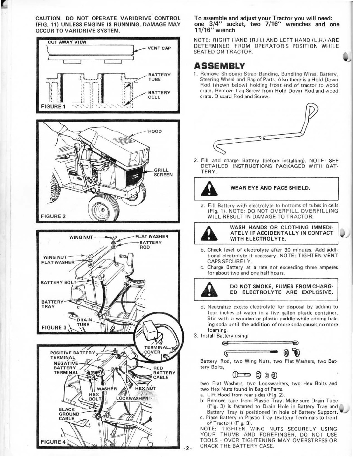
CAUTION
(FIG
OCCUR TO
FIGURE 1
: DO
NOT
OPERATE VARIDRI
. 11) UNLESS ENGINE IS RUNNING.
\?
U=
T
==A=
W
VARIDRIVE
=
A
=
Y
=
V
=
I
=
E
~ S
__.Lj
--
- - - • - - - - - -
SYSTEM.
=
W
============
1
ln
lr
i I : J
l : :
!
~:
1
:
-- . -- - -- .
'-
VE CONTROL
DAMAGE
MAY
==<~VENTCAP
To
assemble and adjust
one 3/4" socket,
11
/16" wrench
NOTE : RIGHT
DETERMI NED FROM OPERATOR
SEATED ON TRACTOR.
HAND
two
(R.H.)
ASSEMBLY
~BATTERY
~
:
~
::
: : •'
..:.J
r1
~
r;
·:
l•
:
TUBE
BATTERY
CELL
1. Remove Shipping
St
eering
Wheel
Rod (shown below) holding f
crate. Remove
crate. Discard Rod and Screw.
St
rap Banding, Bundling Wires, Battery,
and
Bag
Lag Screw from
your
Tractor you
7/ 16" wrenches and
AND LEFT HAND
'S
POSITION WHILE
of
Parts. Al
ront
Hold
so
end
there
is a Ho
of
tractor
Down Rod and
will
need:
(L.H .) ARE
ld
to
one
Down
wood
wood
FIGURE 2
BA
TTERY
TRA
Y
GRILL
SCREEN
2. Fill and charge Battery (before installing). NOTE:
DETAILED
TERY
a.
Fill Batte
(Fig. 1). NOTE: DO NOT OVER
IL
W
b. Check
tional electrolyte if necessary. NOTE:
CAPS SECURE LY.
c.
Charge
for about
d.
Neu
four
Stir
i
ng
foamin
3. Install Battery using:
INSTRUCTIONS PACKAGED WI
.
WEAR EYE
ry
with
L RESULT IN DAMAGE TO TRACTOR.
WASH
ATEL Y IF
WITH ELEC
level
of
Battery
two
and
DO NOT SMOKE,
ED ELEC
tral
ize
exce
inches
of
with
a wooden or plastic paddle while adding bak·
soda
unt
il the addition
g.
e~
;======
AND
FACE
SHIELD
electrolyte
HANDS OR CLOTHING
ACCIDENTALLY IN
electrolyte after 30 minutes. Add addi·
at
a rate
one
TROLYTE ARE
ss
electrolyte
water in a five gallon plastic container.
to
TROLYTE
not
half hours .
FUM
for
of more
==e
bottoms
.
exceeding three amperes
of
FILL.
OVERFILLI
TIGHTEN
ES FROM
EXPLOSIVE.
disposal
soda
causes
TH
.
tubes in cells
IMMED
CONTACT \j_J
CHARG·
by
addi
no more
SEE
BAT
NG
I·
VENT
ng
to
·
<S
Battery Rod,
tery Bolts,
two
Fiat
two Hex
a. Lift
b. Remove tape from Plastic Tray. Make
(Fig. 3) is fastened
Battery Tray
Place
c.
of Trac
NOTE:
YOUR
TOOLSCRACK
· 2 ·
two Wing
Q)::::B
Wash
ers, tw
Nuts found in
Hood from rear
Battery in Plastic Tray (Battery Terminals
TIGHTEN
THUMB AND FOREFINGER. DO NOT U
THE
is
tor) (Fig. 3).
OVER
BATTERY
Nuts,
@)
o Lockwash
Bag
sides
to
positioned in hole
WING NUTS SECURELY USING
TIGHTENING
CASE.
®~
two
Flat
Washers,
(g
®
ers, two
of Parts.
(Fig. 2).
su
Drain Hole in Batt
of Battery Support .
MAY
OVERSTRESS OR
two
Hex Bolts
re
Drain Tube
ery Tray and
to
front
Bat·
and
SE
Page 5
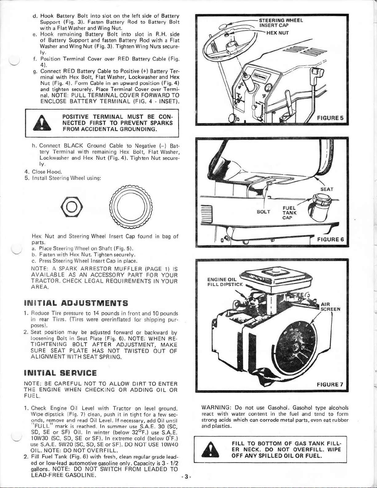
d. Hook Battery
Suppo
rt
with
a Flat
e. Hook remaining Battery
of
Battery Support
Washer
ly.
Pos
iti
f.
on
Bolt
(Fig. 3). Fasten Battery Rod
Washer
and
Wing
Terminal Cover over RED Battery Cable (Fig.
into sl
and Wing Nut.
and
fasten Battery Rod
Nut
(Fig. 3). Tighten Wing Nuts secure-
4).
g. Connect RED Battery Cable
minal
with
Hex
Nut
(Fig. 4). Form
and tighten securely.
nal. NOTE:
ENCLOSE
Bolt, Fiat
Cable
PULL
BATTERY TERMINAL
Place
TERMINAL
ot
on
the
left
side
of Battery
to
Battery
Bolt
into slot in R.H. side
to
Positive
Washer,
in
Lockwasher and Hex
an
upward position (Fig.
Terminal Cover over Termi-
COVER FORWARD
(FIG. 4 - INSET).
with
(+)
Battery Ter·
a Flat
Bolt
4)
TO
POSITIV
NECTED FI
FROM ACCIDENTAL GRO
h. Connect
tery Terminal
Lockwasher and Hex
ly.
4. Close Hood.
5.
Install Steering
BLACK
@
Hex
Nut
Place
Steering
Press
Steering Wheel
and Steering
with
SPARK ARRESTOR
parts.
a.
b. Fasten
c.
NOTE: A
AVAILABLE
TRACTOR. CHECK
AREA.
E TERM
Ground Cable
with
Wheel
using:
Wheel
on Shaft (Fig. 5).
Hex
Nut
. Tighten
AS AN ACCESSORY PART FOR YOUR
LEGAL
INAL
MUST BE CON-
RS
T TO PREVENT
UNDI
to
remaining Hex Bol
Nut
(Fig. 4). Tighten
Wheel
Insert
secure
Insert
Cap
MUFFLER
REQUIREMENTS IN YOUR
Negative (- ) Bat-
Cap
found in
ly.
in
place
.
t,
(PA
SPARKS
NG.
Flat Washer,
Nut
secure-
bag
GE
1)
of
IS
FIGURE 5
INITIAL
1. Red
uce
Tire pressure
re
ar
in
poses).
2.
Seat
loosening Bolt in
TIGHTENING
SURE SEAT PLATE HAS NOT TWISTED
ALIGNMENT
Tires. (Tires were overinflated
position may
INITIAL
NOTE: BE
THE
FUEL.
1. Check Engine
Wipe dipstick (Fig. 7) clean, push
onds, remove and read
"
FULL"
\,.__..
SO,
'IOW30
use
OIL.
2. Fill Fuel Tank (Fig. 6)
ed
gallons. NOTE:
LEAD-FREE GASOLINE. .
CAREFUL
ENGINE WHEN CHECKING
mark
SE
or
(SC,
S.A.E. 5W20
NOT
E:
or
low-l
ead
ADJUSTMENTS
to
14 pounds in
be
adjusted forward
Seat
Plate
(Fig. 6). NOTE: WHEN
BOLT
WITH
AFTER
SEAT SPRING.
ADJUSTMENT,
SERVICE
NOT
TO
ALLOW
OR
Oil
Level
with
Tractor
it
Oil
Leve
l.
is
reached. In summer
SF)
Oil. In
SO,
(SC,
DO
NOT
automotive gasoline
DO
SE
or
SO,
OVERFILL.
NOT
winter
SF). In
with fresh,
If necessary,
(below
ext
reme
SE
or
SF). DO NOT
clean regular
SWITCH FROM LEADED
only
front
and 10 pounds
for
shippi
or
backward by
DIRT
TO ENTER
ADDING
on
in
level ground .
tight
for a few
add Oil
use
S.A.E.
32°F
.)
use
cold (below 0°F.)
USE
grade
. Capacity
ng
MAKE
OUT
OIL
until
30
S.A.
10W40
lead-
is 3-1/2
pur-
RE-
OF
OR
sec-
(SC,
E.
TO
WARNING:
react
strong acids which can corrode metal parts, even eat rubber
and plastics.
A
3.
Do
not
use
with
water content in the fuel and tend
FI
LL
TO BOTTOM OF GAS
ER NECK. DO
OFF ANY
Gasohol. Gasohol type alcohols
NOT OVERFILL. WIPE
SPILLED
OIL
OR
TANK
FUEL
FIGURE 7
to
form
FIL
L-
.
Page 6
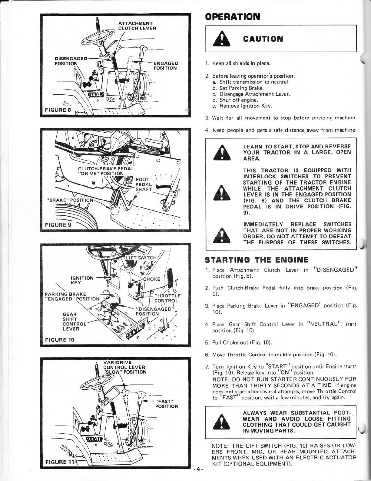
ATTACHMENT
CLUTCH
LEVER
OPERATION
--h_
FIGURE 8
[A
1.
Keep
2.
Before leaving operator's position:
a.
Shift
b.
Set
c.
Disengage
d. Shut
e.
Remove
3. Wait for all movement to stop before
Keep people
4.
CAUTION
all shields in place.
transmission to neutral.
Park
ing Brake.
Attachment
off
engine.
Ignition Key.
and
pets a
LEARN
YOUR TRACTOR IN
AREA.
THIS TRACTOR
INTERLOCK SWITCHES TO
STARTING
WHILE
LEVER
(FIG.
PEDAL
9).
Lever.
safe
TO START,
OF
THE ATTACHMENT CLUTCH
IS
IN
8)
THE ENGAGED POSITION
AND
IS
IN
distance
STOP
IS
THE TRACTOR ENGINE
THE CLUTCH BRAKE
DRIVE
serv
icing machine.
away
from machine.
AND
A LARGE, OPEN
EQUIPPED WITH
REVERSE
PREVENT
POSITION (FIG.
PARKING
"ENGAGED"
FIGURE 10
BRAKE
GEAR
SHIFT
CON
LEVER
IGNITION
KEY
POSITION
TROL
~
~
_.....,;::.QJ""ol
VARIDRIVE
CONTROL
"SLOW"
LEVER
POSITION
--~--------
"FAST"
POSITION
IMMEDIATELY
THAT
ORDER. DO
THE
STARTING
1. Place
2.
3.
4.
5. Pull Choke
6.
7.
Attachm
position (Fig. 8).
Push
Clutch-Brake
9).
Place
Parking Brake Lever in
10).
Place
Gear
Shift Control
position (Fig.
Move
Throttle Control
Turn Igni
(Fig.
10).
NOTE:
MORE
does
not start after
to
"FAST"
10).
out
tio
n Key to
Release
DO
NOT RUN STARTER CONTINUOUSLY FOR
THAN
position, wait a few minutes,
ALWAYS WEAR
WEAR
CLOTHING
IN
REPLACE SWITCHES
ARE NOT
PURPOSE
THE
ent
Clutch Lever in "DISENGAGE
Pedal
(Fig. 10).
to
"START"
key
into
THIRTY
several
AND
MOVING
IN
PROPER WORKING
NOT
ATTEMPT TO
OF THESE SWITCHES.
ENGINE
fully
into
brake position (Fig.
"ENGAG
Lev
er
middle position (Fig. 10).
position
"ON"
SECONDS
attempts, move Throttle Control
SUBSTANTIAL
AVOID
THAT
COULD GET CAUGHT
PARTS.
in
"NEUTRAL",
position.
AT
LOOSE
ED"
until
A TIME.
and
DEFEAT
D"
position (Fig.
start
Engine starts
If
engine
try
again.
FOOT-
FITTING
I
~
~
\..,l
}'
NOTE: THE
ER
S FRONT,
MENTS WHEN USED WITH
KIT
(OPTIONAL EQUIPMENT).
LIFT
SWITCH (FIG. 10) RAISES
MID,
OR
REAR MOUNTED
AN
ELECTRIC ACTUATOR
OR
LOW-
ATTACH-
Page 7
WARMING
Move
Throttle
as eng
ine warms up. NOTE:
FOR A
FEW
Control
MINUTES BEFORE OPERATING.
UP
THE
to
"SLOW"
ENGINE
ALLOW
position.
ENGINE TO WARM UP
Push
Choke in
When restartinP. a warm en9ine, move T
way between
have
to
be
'SLOW"
used.
and
'FAST"
position. Choke
TRACTOR OPERATION
1. With engine running and warm, place
way between
2.
Push
Clutch-Brake
Brake
9)
.
3. M
ove
4.
Releas
movement.
5.
Move Varidrive Control Lever to desired
If
grou
NOTE: ALWAYS SELECT A GROUND
THAT
ME
NT
A
A
"SLOW"
and
hold Clutch-Brake
Gear
Shift
e Clutch-Br
nd
trave
l is too slow
WILL SUIT THE
BEING USED.
DO
TROL UNLE
TRANSAXLE
DAMAGE
SYSTEM.
BRING
BEFORE SHIFTIN G GEARS.
NEVER PLACE YOUR HANDS
IN
MENT
WHILE TRACTOR
ATTACHMENT IS RUNNING .
and " F
AST"
Pedal
down
firmly
Peda
Control Lever to desired
ake
Pedal
SLOWLY to start forward
advance
TERRA
NOT OPERATE
OR
SS
ENGINE IS RUNNING .
DAMAGE
MAY
OCCUR TO
TRA
CTOR TO COMPLETE
UNDER
OR
ANY POW
NEAR
position.
l in Brake
Throttle Lever.
IN AND THE
VAR
ANY
OR
hrottle
Throttle
to
Control
may
Control mid-
disengage
position (Fig.
gear
(Fig. 10).
speed (Fig.
TRAVEL
ATTACH
IDRIVE
MAY
VARIDRIVE
ERED ATTACHMOVING
ANY POWERED
CON-
RESULT.
STOP
OR
FEET
PART
mid
not
Parking
11)
SPEED
·
FIGUR E 12
2.
Move
Shift
.
3. P
lace
-
4.
Place
tion
5.
Move Throttle Contr
6.
Move
7.
Turn Ignition Key to
Control Le
Parking
and
Brake in
CLUTCH-BRAKE PEDAL
MAIN
FOOT PRESSURE IS RELEASED.
Attachment Clutch Lever in
lower attachment to the wound.
Varidrive Control Lever
REMOVE
TOR TO
US
MAKE
HOLD
ver
to
"NEUTRA
"ENGAGED"
COMPLETELY DEPRESSED WHEN
ol to "SLOW position.
"OF
E.
SURE PARKING BRAKE
TRACTOR SECURE.
to
F" position.
KEY
WHEN
PREVENT
L" position.
position.
SHOULD RE·
"DISENGAGED"
"SLOW" position.
LEAVING
UNAUTHORIZ
posi
TRAC-
ED
WILL
-
DO
NOT OPERAT
OUT E
ITH
ER THE
CHER,
THE DEFLECTOR SHIE
NOTE: ALWAYS OPERATE ENGINE
RPM
WHEN MOWING TO ASSURE BETTER MOWING
FORMANCE, LONG ENGINE
CHARGE OF CUT
ON
MATERIAL.
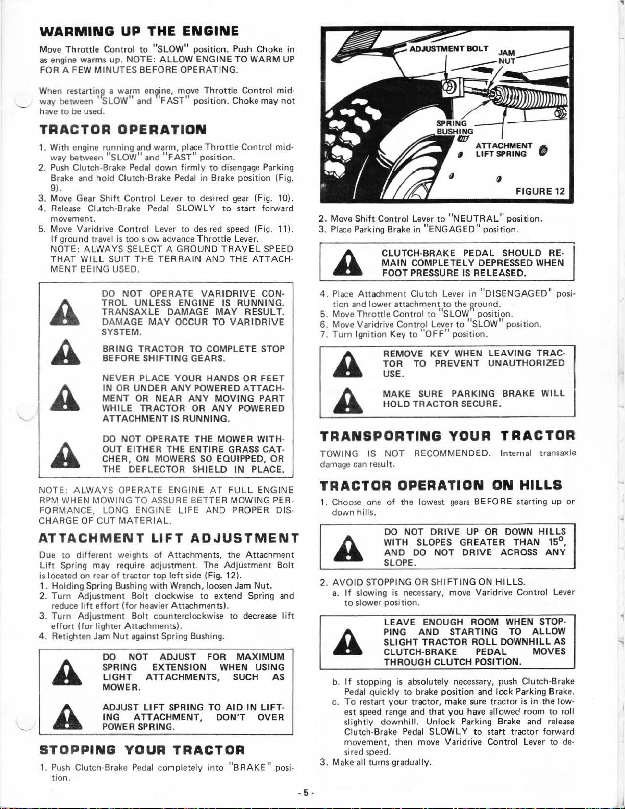
ATTACHMENT LIFT
Due
to
different weights
Lift
Spring may require adjustment. The Adjustment
is
located on rear
1. Holding Spring Bushing
2. Turn Adjustment
reduce
lift
3.
Turn Adjustment
effort
4. Retighten
(for
STOPPING
1.
Push
Clutch-Brake
tion.
of
tractor top
with
effort
lighter Attachments).
Jam
Bolt
(for
heavier Attachments).
Bolt
counterclockwise to
Nut
against Spring
DO
NOT ADJUST FOR
SPR
IN G EXTENSION WHEN USING
LIGHT
MOWER.
ADJUST
ING
POWER
ATTACHMENTS, SUCH AS
LIFT
ATTACHMENT,
SPRING.
YOUR TRACTOR
Pedal
E THE MOWER WITH-
MOWERS
ENTIRE GRASS
SO
EQUIPPED,
LD
AT
LIFE
AND PROPER DIS-
ADJUSTMENT
of
Attachments, the Attachment
left
side
Wrench, loosen Jam
clockwise to extend Spring
SPRING TO
completely i
(Fig. 12}.
Bushing.
DON'
nto
IN
PLACE.
FULL
Nut.
decrease
MAXIMUM
AID
IN
T OVER
"BRAKE"
CAT
·
OR
ENGINE
PER
Bolt
and
lift
LIFT
-
posi-
TRANSPORTING
TOWING
damage
can
IS
NOT
result.
RECOMMENDED. Internal transaxle
YOUR
TRACTOR
TRACTOR OPERATION ON HILLS
-
1.
Choose
down hills.
2.
AVOID
a.
b.
c.
3. Make all turns gradually.
. 5 .
one
of
the lowest g
DO
NOT
WI
TH SLOPES GREATER
AND
DO
SLOPE.
STOPPING
If
slowing
to
slower pos
If
stopping
Pedal
quickly to bra
To restart your tractor, make
est
speed
slig
htly downhill. Unlock Parking Brake
Clutch-Brake
movement, then move Varidrive Control Lever to
sired
speed.
OR
is
necessary,
iti
on.
LEAVE
PING
SLIGHT TRACTOR
CLUTCH-BRAKE
THROUGH C
range
ENOUGH ROOM WHEN STOP-
AND
is
absolutely
and
Pedal
ears
DRIVE
NOT
DRIVE
.
SHIFTING
move Varidrive
STAR
LUT
CH
necessary,
ke
positi
on
that you
SLOW
LY
BEFORE starting up
UP
OR
ACROSS
ON
HILLS
TIN
G TO
ROLL
DOWNHILL AS
PE
DAL
POSITION.
push Clutch-Brake
and lock Parking Brake.
sure
tractor
have
allow
to
statt tractor forward
DOWN
HILLS
THAN 15°
.
Control Lever
ALLOW
MOVES
is
in the low-
ed
room
and
AN
Y
to
roll
release
de·
or
,
Page 8
CHARGING
1. Connect
terminals
chassis)
2. Conne
(-)
3. Connect the other end
or
Ta
4. Disconnect
a.
b. Negative terminal
c.
each
end
of the
of
each
of
fully
cables
ck
or
battery (taking
of
the
charged battery.
in
revers
chassis
of
.
ct
one end
terminal
good CHASSIS GROUND
nk
or
Battery).
Engine Blo
Positive terminals.
RED cable to the POSITIVE (+)
care
not
to
short against
BLACK cable
of
the cable
on
e order:
of
tractor.
fully
charged battery.
to
the
to
ENGINE BLOCK
tractor (away
NEGAT
from
IVE
Gas
FIGU RE
FIGU
13
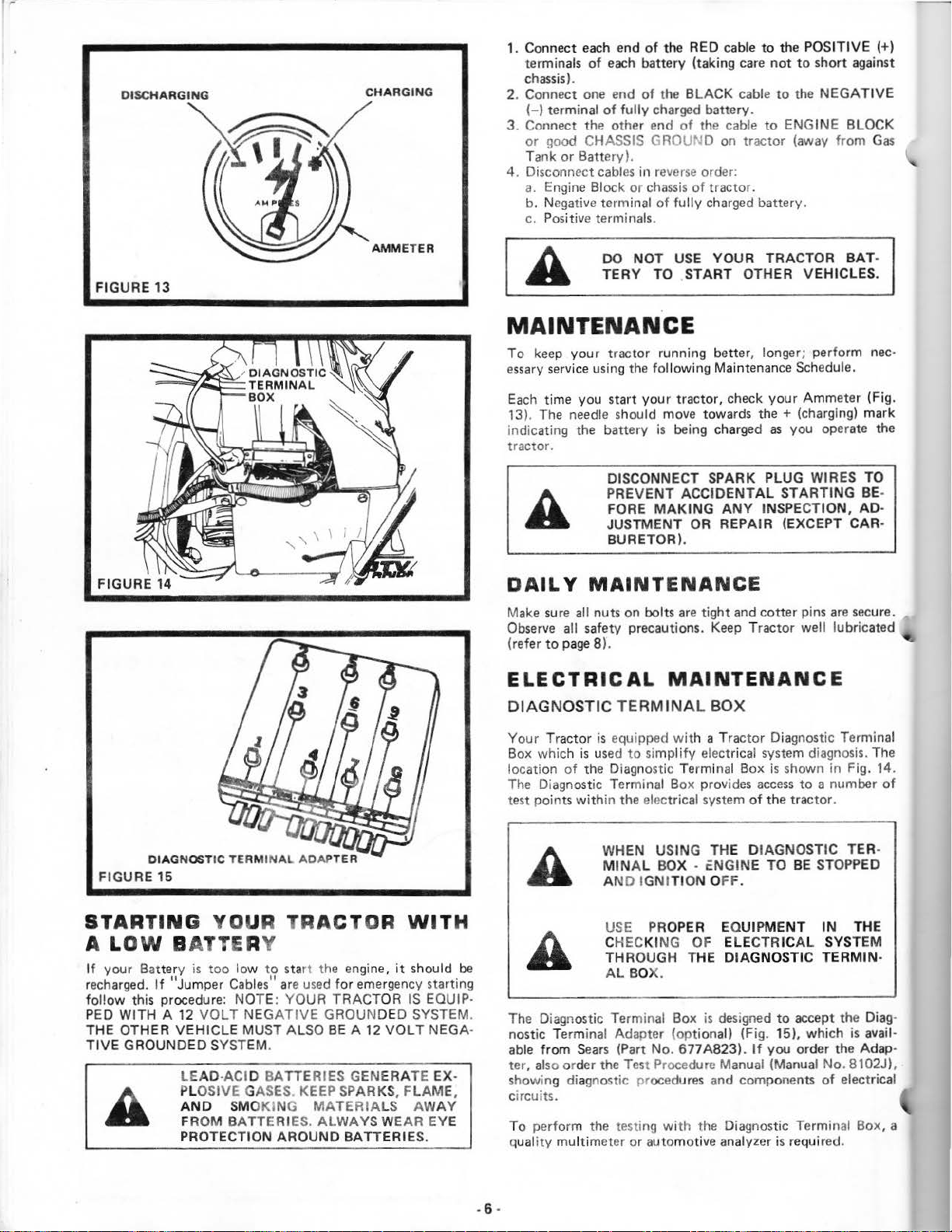
AMMETER
DO NOT
TERY TO .START OTHER
USE
YOUR TRACTOR
MAINTENANCE
To
keep
essary
Each time
13).
indicating the battery
tractor.
DAILY MAINTENANCE
Make
Observe
(refer
ELECTRICAL
DIAGNOSTIC TERM
your tractor running better, longer; perform
service using the following Maintenance Schedule.
you start your tractor, check
The
needle
should move towards
is
DISCONNECT SPARK PLUG WIRES TO
PREVENT
FORE
JUSTMENT OR REPAIR (EXCEPT CARBURETOR).
sure all nuts on bolts
all safetY precautions.
to
page 8).
MAK
being charged
ACCIDENTAL
ING
are
tight and cotter pins
ANY
Keep
the+
INSPECTION, AD·
Tract
MAINTENANCE
INA
L BOX
VEH
ICLES.
your
Ammeter (Fig.
(charging) mark
as
you operate the
STARTING BE-
well
are
lub
or
BAT
nee·
secure.
ricated
·
DIAGNOST
FIGU
RE
15
STARTING YOUR
A LOW B
If your Battery is too low to start the engine,
recharged.
follow
PED WITH A
THE OTHER VEHICLE MUST ALSO
TIVE
If
this procedur
GROUNDED SYSTEM.
IC
TERMI
NAL
ADAPTER
TR
ACTOR WITH
ATTE
"Jumper Cables" are
12
VOLT
LE
AD
PLOSIVE GASES.
AND
FROM BATTERIE
PROTECTION AROUND BATTERIE
RY
e:
NOTE: YOUR
NEG
ATIVE
-ACID
BAT
SMOKING
used
for emergency starting
TRACT
GROUNDED SYSTEM.
BE
A 12
TERIES GEN
KEEP SPARKS,
MATERIA
S.
ALWAYS WEAR EYE
it
OR
IS EQUIP·
VOLT
ERA
FLAME,
LS
should
NEGA·
TE EX-
AW
AY
S.
be
Yo
ur
Tractor
Box which
locati
on
The Diagnos
test points
The Diagnostic Terminal Box
nostic Terminal Adapter (optional) (Fig. 15), which is avail·
able from
als
ter,
showing diagnostic procedures and components
circuits.
To perform the testing
q
ua
lity mul
is
equipped
is
used
to
simp
of
the Diagnostic Termi
tic Terminal Box provid
withi
n the electrical system
WHEN
MIN
AL BOX - eNGINE TO
AND IGNITION O
USE
PRO
CHECKING OF ELECTRICAL SYSTEM
THROUGH
AL BOX.
Sears
(Part No. 677A823).
o order the
timet
Tes
t Procedure Manual (Manual No. 8102J).
er
or
automot
wit
h a Tractor Diagnostic Terminal
lify
electrical system diagnosis.
nal
Box
is
shown in Fig. 14.
es
access
to
a number
of
the tractor.
US
ING TH E DIAGNOSTIC TER-
BE STOPP
FF.
PER
EQUIPMENT
THE DIAGNOSTIC TERMIN·
is
designed
If
you order the Adap·
with
the Diagnostic Terminal Box, a
ive
analyzer
to
accept the
is
requir
IN
of
ed
The
of
ED
THE
Diag
electrical
.
·
. 6 .
Page 9
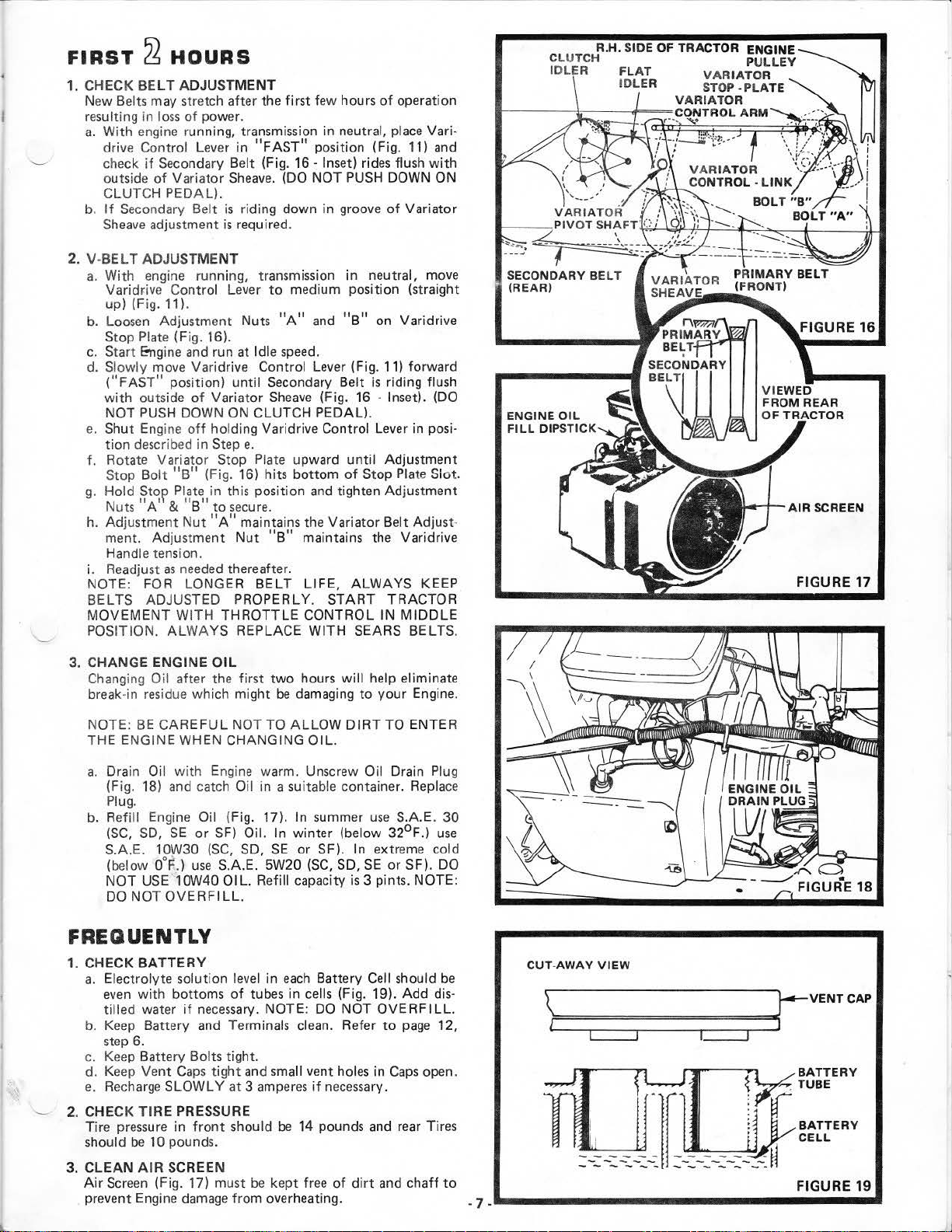
FIRST
1.
CHECK
New Belts may stretch after the
resulting in
a.
b.
2.
V-BEL T ADJUSTMENT
a.
b. Loosen Adjustment Nuts
c.
d. Slowly move Varidrive Control Lever (Fig. 11) forward
e.
f. Rotate Variator Stop Plate upward until Adjustment
g.
h. Adjustment
i. Readjust
NOTE: FOR LONGER
BELTS ADJUSTED PROPERLY.
MOVEMENT
POSITION.
~
HOURS
BELT
ADJUSTMENT
loss
of
With engine running, transmission in neutral, place Varidrive Control Lever in
check
if
outside
CLUTCH PEDAL).
If
Sheave
With engine running,
Varid~ive
up) (Fig. 11).
Stop Plate (Fig. 16).
Start Engine
("FAS
with
NOT
Shut Engine
tion
Stop
Hold
Nuts
ment. Adjustment
Handle tension.
of
Secondary Belt
adjustment
T"
outside
PUSH
described in Step
Bolt
Stop Plate in this position
"A'
power.
Secondary Belt (Fig. 16 · Inset) rides flush
Variator
Control Lever
position) until Secondary Belt
DOWN ON CLUTCH PEDAL).
"B"
& "
as
need
WITH
ALWAYS
Sheave
is
is
required.
and
run at Id
of
Variator
off
holding Varidrive Control Lever in posi-
(Fig. 16) hits
B"
to
secure.
Nut
"A"
Nut
ed
thereafter.
THROTTLE
REPLACE
first
few hours
"FAST"
riding down in groove
transm1ss1on
e.
maintains the Variator Belt Adjust·
BEL
position (Fig. 11) and
. (DO NOT PUSH DOWN
to
medium position (straight
"A"
and
le
speed.
Sheave
"B"
(Fig. 16 · Inset). (DO
bottom
and
maintains the Varidrive
T LIFE,
START
CONTROL IN
WITH
of
ope
of
Variator
in neutral, move
"B"
on Varidrive
is
riding flush
of
Stop Plate Slot.
tighten Adjustment
ALWAYS
TRACTOR
MIDDLE
SEARS BELTS.
ration
with
ON
KEEP
ENGINE
FILL
DIP
OIL
STICK
AIR
SCREEN
FIGURE 17
3. CHANGE ENGINE
Changing Oil after the
break-in residue which might
NOTE:
THE
a.
b.
BE
CAREFUL
ENGINE WHEN CHANGING
Drain Oil wi
(Fig. 18) and catch
Plug.
Refill Engi
(SC,
SD,
S.A.E. 10W30
(below
NOT
DO
0°F.)
USE
NOT
OVERFILL.
OIL
first
two
be
damaging
NOT TO
th
Engi
ne
Oil in a suitable container. Replace
ne
Oil (Fig. 17). In summer
SE
or
SF)
Oil. In winter (below
(SC,
use
.10W40
SD,
S.A.E. 5W20
OIL.
ALLOW
warm. Unscrew Oil Drain Plug
SE
or
Refill capacity
hours
will
help eliminate
to
your
Engine.
DIRT
OIL.
SF). In extreme cold
(SG,
SO,
TO ENTER
use
S.A.E.
32°F
SE
or SF). DO
is
3 pints. NOTE:
30
.)
use
FREQUENTLY
1. CHECK
a.
b. Keep Battery and Terminals clean. Refer
c.
d. Keep
e.
2. CHECK
Tire pressure in
should
CLEAN
3.
Air
prevent Engine damage from overheating. • 7 _
BATTERY
Electrolyte solution
even
with
bottoms
tilled
water
if
step 6.
Keep Battery Bolts tight.
Vent
Recharge
Screen
Gaps
SLOWLY
TIRE
PRESSURE
be
10 pounds.
AIR
SCREEN
(Fig. 17) must
leve
of
necessary.
tight
at 3 amperes
front
should
and small vent holes in
l in
each
Battery Cell should
tubes in cells (Fig. 19). Add dis-
NOTE: DO NOT
if
necessary.
be
14 pounds and rear Tires
be
kept free
of
dirt
OVERFILL.
to
page
12,
Gaps
open.
and
chaff
be
to
CUT-AWAY
\?======================~
_,..,...1
-
~
..
______________
VIEW
~VENT
I I 1=-==:J
~
:
.:~~-:.:::.-::.-:
·lr
.:-::-::-:-::-W
:rr
BATTERY
::::
CELL
FIGURE
_______
CAP
..
v
19
•
Page 10
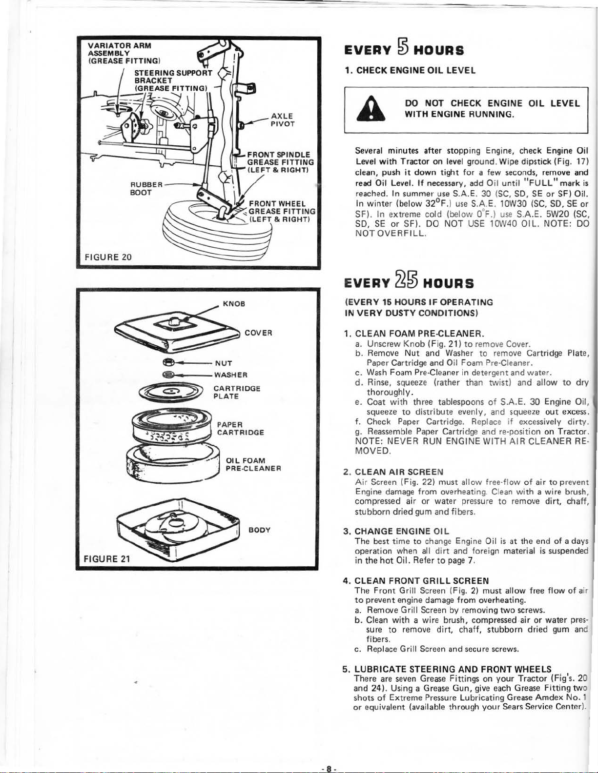
V
ARIATOR
ASSEMBLY
(GREASE FI
ARM
TTING
- n
)
EVERY
1. CHECK ENGINE
Several
l evel
clean,
r
ead
reached. In
In
winter
SF).
SO,
NOT
~
HOURS
DO
WITH
mi
nute
w
ith
Tractor
push
it down
Oil
level.
summer
(below
In
extreme
SE
or
SF).
OVERFILL.
OIL
LEVEL
NOT
CHECK
ENGINE
s aft
er stopping
on
level
tight
If necessary,
use S.A.E.
32°F.)
cold
use S.A.E. 10W30 (SC, SO,
(below o· F.) use
DO NOT USE 10W40
ENGINE OIL
RUNNING
Engine,
ground
for a few seconds,
add Oil
30
LEVEL
.
check
Engine Oil
. Wipe dipstick (Fig.
remo
ve and
until
"FULL" mark
(SC, SO,
SE
S.A.E.
OIL.
or
SF)
5W20
NOTE: DO
SE
17)
is
Oil.
or
(SC,
FIGURE
FI
GURE 21
20
® • WASHER
c
c<===>
~
~t:;:
ID
GE
O
IL
FOAM
PRE.CLEANER
BODY
EVERY
(EVERY
IN VERY
1. CLEAN
a. Unscrew
b.
c.
d.
e.
f.
g. Reassemble Paper Cartridge
NOTE:
MOVED.
2.
CLEAN
Air
Engine
compressed
stubborn
3.
CHANG E ENG INE
The
operation
in
~0
15 HOU
Remove
Paper Cartridge
Wash
Rinse,
t
horoughly.
Coat
squeeze
Check
Screen
damage
best
the
hot
RS
DUS
TY
CONDIT IONS)
FOAM PR
Knob
Nut
Foam
Pre·Ciea
squeeze
with
three
to
distribute
Paper Cartridge. Repl
NEVER
AIR
SCREE
(Fig.
from
air
dri
ed
gum
time
to
when
Oil. Refer
HOURS
IF
OPERATING
E·CLEANE R.
(Fig.
and
Washer
and Oil Foam
ner
(rather
tablespoons
RUN ENGINE WITH
N
22)
must all
overheating. Clean
or
water
and
OIL
change Engine Oil
all
dirt
to
21)
to
remove Cover.
to
in
detergent
than twi
evenly ,
and
ow free-flow
pressure
fibe rs.
and
foreign material
page 7.
remove Cartridge Plate,
Pre-Cl
eaner.
and
water.
st)
and
allow
to
of
S.A.E.
30
Engine Oil,
and
squeeze
ace
if excessively
re-
position
AIR
with
to
remove
is
at
out
on
CLEANER
of
air
to
a wire brush,
dirt,
the
end
is
suspended
excess.
dirty.
Tracto
prevent
chaff,
of
a days
dry
r.
RE·
-8 -
4 . CLEAN
The
Front
to
prevent
a. Remove
b.
Clean
sure
fibers.
c. Replace
5.
LUBRICATE
There
and
24 ). Using a Grease Gu
shots
of
or
equivalent
FRONT GRILL
Grill
Screen
engine
Grill
Screen
with
a wire
to
remove
Gri
ll
Screen
STEERING
are seven Grease Fittings
Extreme
(available
SCREEN
(Fig. 2)
damage
Pressure Lubricat ing Grease
from
by removing
brush,
dirt,
chaff,
and
secure
AND
n,
through
compressed
must
allow free flow
overheating
two
stubborn
screws.
FRONT
on
your
give
each
your
Sears Servi
water
gum
S
(Fi
ce
Center) .
of air
g's.
No.
pres-
anc
20
.
screws.
air
or
dried
WHEEL
Tractor
Grease Fitting two
Amdex
1
Page 11
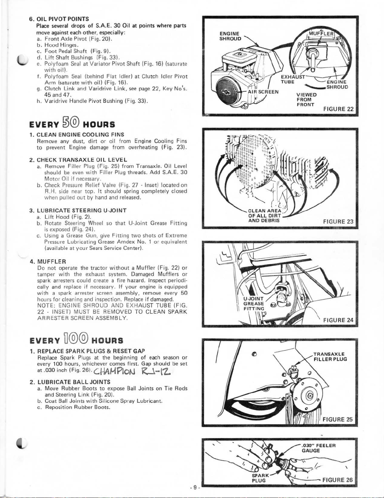
6.
0 1 L PI
VO
T POINTS
Place several drops
aga
move
a.
b. Hood Hinges.
c.
d.
e. Polyf
f.
g.
h. Varidri
inst
Fro
nt
Axle
Foot
Pedal
Lift
Shaft Bushings (Fig. 33) .
oam
with
oil).
Polyfoam
Arm
(saturate
Clutch
45an
Link
d47.
ve
of
S.A.E.
each
other, especia
Pivot (Fig. 20).
Shaft (Fig.
Seal
at
Variator
Seal
(behind
with
oil)
and Varidrive
Handle P
ivot
30
Oil
at points where
lly
:
9).
Pivot
Shaft (Fig. 16) (saturate
Flat
Idler)
at
Clutch Idler Pivot
{Fig. 16).
Link,
see
page 22, Key No's.
Bushing (Fig. 33).
part
.s
ENGINE
SHROUD
VIEWED
FROM
FRONT
FIGURE
22
EVERY
1. C
LEAN
Remove any dust,
to
2.
CHECK
a.
b.
3. LUBRICATE
a.
b. Rotate Steering Wheel so
c.
4.
MUFFLER
Do
tamper
spark arresters could create a fire hazard. Inspect periodi·
cally and replace
with
hours
NOTE: ENGINE SHROUD
22
ARRESTER SCREEN ASSEMBLY.
~@
ENGINE
preve
nt
TRANSAXLE
Remove Filler Plug (Fig. 25) from Transaxle. Oil Level
be
should
Motor
Oil
Check
Pressure
R.H. side near top.
when pulled
Lih
Hood (Fig. 2).
is
exposed (Fig. 24).
Using a
Pressure
(available at
not
operate the tractor
with
a spark arrester screen assembly, remove every 50
for
cleaning and inspection. Replace
· INSET) MUST
HOURS
COOLING
Engine d
Grease
Lubricating
dirt
even
with Fill
if
necessary.
Rel
out
by
STEERING U-
Gun, give
your
Sears
the exhaust system. Damaged
if
necessary.
FINS
or
oil from Engine Cooling Fins
amage
BE
from overheating (Fig. 23).
OIL
LEVEL
er Plug threads.
ief
Valve
(F1g.
It
should spring completely closed
hand
and
JOINT
Fitting
Grease
Service Center).
without a Muffler
AND
REMOVED TO
27 · Inset) located on
released
that
U·Joint
two
Amdex No. 1
If
your
EXHAUS
Add
S.A.E.
.
Grease Fitting
shots
of
or
equivalent
(Fig. 22)
Muff
engine
is
if
damaged.
T TUBE (FIG.
CLEAN
Extreme
equipped
30
or
lers
or
SPARK
FIGURE
FIGURE
23
24
EVERY
1. REPLACE
Replace
every 100 hours, whichever comes first. Gap should be set
.030 inch (Fig. 26).
at
2.
LUBRICATE
a.
b. Coat Ball Joints with Silicone Spray Lubricant.
c.
D@@
SPARK
Spark
HOURS
PLUGS & RESET GAP
Plugs
at the beginning
C.HA~Plo~
BALL
JOINTS
Move Rubber Boots
and Steering L
Reposition Rubber Boots.
ink
(Fig. 20).
to
expose Ball Joints on T
of
each
season
R-.1-l'Z.
ie
or
Rods
TRANSAXLE
FIL
LER PLUG
FIGURE
25
Page 12

FIGURE
27
EVERY~@
1. REPLACE
Refer
to
page 8.
2.
REPLACE IN-
filte r
If fuel
replacement
a. With Engine
removed
b. Place n
on
side
L.
H.
SIDE
@
HOURS
AIR
CLEANER PAPER
LINE FUEL
is
clogge
is
required.
cool,
from
both
ew
Fuel Fil
of
Filter
in
BE
SURE THERE ARE NO
LEAKS
PROPER POSITION IN
FIL
d,
obs
tructing
remo
ve
ends
of
ter
in
direction
AND
and
position
THAT
CARTRIDGE
TER
fuel flow
plug Fuel
Fuel Filt
in Fuel Line
of
fuel flow) .
FUEL
HOSE
to
carb
Line Sections
er (Fig. 28).
FUEL
LINE
CLAMPS.
uretor
(arrow
LINE
IS
,
as
IN
STEERING
LINK
EVERY~
1. CHANGE
a. Bl
ock
move
b. Drain Transaxle
and cat
Plug.
Ref
c.
Oil. Capac i
of
Transaxle)(F
Transaxle
d. Check
closed
e.
Repo
AS
NEEDED
1. TOE-IN ADJUSTMENT
If
any
replaced, Tie Rod
a. Loosen
justment
b.
Adjust
10
- 1 /
c.
On
ce
nter
d.
On
ce
nter
e.
Compar
1/8
f.
If
not
surement.
g.
Tight
parallel (180
proper
@@
TRANSAXLE
up
Rear Axle securely
left
Rear Wheel by removing
Oil
ching
Oil in
ill
Transaxle
Pressure Relief Va lve.
when
sition
parts in F r
Jam
Sleeves.
bot
2"
from
front
(measurement
rear
of
(mea
e measurem
- 1/4 less than
adjust
en
Jam
front wheel Toe-In
with
ty
is 5 quarts
ig.
27
to
fill
more
pulled
wheel.
Secure
ent
Axle
adjustment
Nuts
(Fig.
h Tie Rods
center to center.
of
front
tires measure dista nce
front
tires measure distance
surement No.2).
measureme
each
Nuts
°)
to
HOURS
OIL
by
suitable
quickly.
out
No. 1).
ents -measurement
Tie
making
each
or
use a
Tractor
Hub
Bolts (Fig.
removing Drain Plug (Fig.
container. Replace
S.A.E.
- Inset)
30 (SC, SD
. Pressure Relief Valve (R.H . side
may
be
It
should
by
hand
and
with
Hub
or
Steering
is
required .
29)
at
each
so
that
Tie Rod
nt
equally
other.
No.
sure
This adjus
and
Rod
held
spring
released.
Bolts.
Mechani
end
of
Joints
from
from
No. 1
2.
to
get
Tie
Rod
Steer
ing
or
SE)
open
comple
sm
Tie
correct
Joints
tment
operation.
Jack
. Re-
36)
27)
Drain
Motor
to
allow
tely
are being
Rod Ad-
measure
center
center
shou
ld be
mea-
secures
.
to
to
are
•f
-10-
Page 13

2.
BRAKE
a.
b. Loos
c.
d. Depress Brake-Clutch
e.
f.
3.
CARBURETOR
Never
preset at the factory and should only
fied servi
a. Adjust Carburetor
ADJUSTMENT
IF
TRACTOR
SIX
FEET
HIGHEST
CONCRETE OR
BRAKE
Remove (4) Hex Washer Head Tapping Scre
Shift
Cover Plate (Fig. 30) located on
and remove the plate.
en
(Fig. 31).
Rotate Brake Rod
Band Assembly (E)
31
Lever (G) in the
(H) (Fig.
Rotate Brake Rod (B) clockwise
pressed
Tight
(Fig. 31).
.. Turn Needle Valve clockwise, closing finger
--
CAUTION
Jam
).
31A)
to
en
Jam
attempt
ce
technician
ONLY,
(Fig. 32).
Turn Idle Valve clockwise, closi
and then
MUST
Nut
fo
.
1 -
3/8"
Nut
ADJUS
to
change
and then turn counterclockwise 1 -
turn
counterclockwise 1 -
: Valves may
REQUIRES MORE
STOPPING DISTANCE
GEAR
(A) on Brake Rod
(B)
counterclockwi
is
clear
rward second notch on the Lockbar
(Fig. 31).
(A) on Brake Rod (B)
TMENT
who
to
suggested
ON A
PAVED
BE ADJUSTED.
of the
Pedal
maximum
has
be
damaged
SURFACE
Brake Drum (F) (Fig.
and position Park Brake
until
eng
be
the necessary equipment.
initial settings.
ng
THAN
IN
LEVEL
top
(B)
se
unt
Spring (D)
ine
changed by a quali-
finger
1/2
if
turned in
DRY
THEN
ws
tractor
at Clevis (C)
at
speed
tight
turns.
from
frame
il the Brake
is
com-
Clevis
. This
tight
1/2
turns
ONLY,
too
(C)
far.
D
1.
is
3/8"
B
(
~?
l.
~
--
..
~
FIGURE
tR\
31
b.
Sta
rt Engine and all
fin
al adjustments
.. With Thro
Throttle Lever against Idle Stop
Ad
RP
begins
clockwise.
--
Set Idle
RPM. When
Stop,
RPM
NOTE:
ADJUSTMENTS MUST
THROTTLE
STOP
With Thr
··
Needle Va l
gins
NOTE:
THROTTLE
"
FAST"
COUNTERCLOCKWISE 1
4.
ADJUSTMENT
It
may
page
7).
REFER TO
PAGE
ttle
justing Screw
M. T
urn
Idle Val
to
miss
Speed Sc
engine
, controlled by governor.
ALL
AND
AT
ott
ve
to miss
IF
ENGINE HESITATES WHEN
POSITIONS,
be occasionally necessary
V-BELT
"STARTING
4.
ow
to warm
with
Engine running .
Control in
to
give an
ve clockw
and
then open 1/2 t
rew
to
Thrott
le Lever
speed
should
ABOVE SPEED
LEVER
le Control in
and then
CONTROL FROM
HELD
SPEEDS NOTED.
slowly
clockwise
set
TURN
THE
for
five minutes. Make
"SLOW"
and
eng
ine
ise slowly
give
engine
is
rel
be
between 1000
AND
FUEL
BE
DONE
AGAINST
"FAST"
1/2 t
/8
until
urn
counterclockwise.
NEEDLE
TURN
to
re-adjust V-Belt.
ENGINE"
position,
set Idle Speed
speed
of
unt
il engine
urn
counter-
speed
of
ease
from Idle
and
MIXTURE
WITH
THE
position, turn
engine
MOVING
"SLOW"
VALVE
MORE.
hold
1400
900
1400
THE
IDLE
be·
TO
(See
Page 14

FIGURE
33
5.
BELT
REPLACEMENT
The be
lts
on this
when replacing Belts always replace
a. Disconnect Battery, Negative Ground Cable.
b.
Set
Parking Brake (Fig. 10).
c.
Pull Varidrive Control L
giving
Pr
imary Belt slack.
d. Remove Prim ary Belt
e.
Remove 3 Bolts and Nuts holding Primary Idler
to
Frame (Fig. 33).
f.
Remove
(Fig. 34). Slide P
Shaft
g.
Remove Belt
h. Remove Id
Sheaves
i.
Primary (Front) Belt can
j.
To
trol
(Fig. 34) and remove Secondary
k.
Rem
I.
Remove Transmission Pulley B
be
m.
Reverse
place Primary Idler
Idler
n. Connect Battery.
NOTE: WHEN A NEW
ED, YOU MUST CHECK
TO
(Fig. 34).
replace Secondary (Rear) Belt move
Lever
ove
Clutching Idler
removed from Transmission Pulley.
the above procedures
and Transmission Pulley Belt
"CHECK
tractor
Klip
Ring and Washer
from
ler
Nuts and Idler
to
fast position. Remove Variator Belt
BELT
are
special
ever to slow
from Engine Pulley (Fig. 34).
ivot
Variator
ADJUSTMENT",
Arm inwards .
now
(Fi
g.
Package,
BELT
BELT
Sheave.
OR BELTS
for
with
from
Sheaves
be
removed.
Belt from Variator.
34).
elt
Guard. Belt can
to
install new Belts. Re·
Belt
Guard.
ADJUSTMENT. REFER
PAGE
this application,
Sears
belts.
position (Fig. 11)
Sheaves
Variator
from
Primary Idler
Varid
Keeper, Clutching
ARE
7.
Pivot
rive Con·
Keeper
now
INSTALL
·
FIGUFIE
35
WASHER
,,
KLIP RING
6. CLEAN
Corrosion and dirt on the Battery and Terminals
the Battery
th
a.
b.
7. TIRE CARE
a.
· b. Keep tires free
c.
d. Removing
e. Removing rear
BATTERY
e charger.
Rem
ove
the Battery from the Tractor and
four
tablespoons
NOTE :
SOLUT ION
plain wate
Clean termin
bright. Replace Battery
ti
Maintain tire pr
at 10 pounds.
cals
Avoid stumps, stones, deep ruts
may
··
··
..
.. Remove (5) H
..
BE
ons with
whi
ch
cause tire
Block
up
Ja
ck.
Remove
moval.
Repa
ir
Klip
Ring securely in axle groove.
BI'Ock
: up rear axle securely
Jack.
Repair tire and
Bolts securely.
AND
TERMINALS
to
"leak"
power and hinders the operation
of
baki
ng
soda
CAREFUL
IN
TO
r, dry and reinstall on Tractor.
als
and cable ends
Vasoline.
essure in
of
gasoline, oil,
can
destroy rubber.
damage.
front
wheel
front
Klip
Ring
tire and
reassemble.
wheel
ub
rea
NOT
THE
CELLS
Cables.
front
for tire
axle securely or use a S
and
Washer
for
tire repair (Fi
Bolts
ssemble
to one gallon
TO GET
. Rin
se
th e Battery
with
a wi
Coat terminal connec·
at 14 pounds
or
insect
control
and
other hazards
repair (Fig. 35).
to
allow wheel
Rep
lace
wash
g. 36).
or
use a Sears
to
allow wheel removal.
. Replace
and
cause
wash with
of
water.
THE
SODA
with
re
bru
sh
until
and
rear ti
chemi·
that
ears
Tractor
er and
snap
Tractor
tighten Hub
of
res
re·
._
____________________________
FIGURE
36
... ·12
WHEN
BEADS
CAN CAUSE
8.
FINISH
Keep tractor finish and seat free
chemica
w
ls
or
battery electrolyte. Protect painted surfaces
ith
automotive type wax.
MOUNTING
ARE
·
SEATED,
AN
EXPLOSION .
TIRES, UNLESS
OVER
INFLATI
of
gasoline, oil, insect
/
ON
Page 15

TROUBLE
POSSIBLE CAUSE
W
ILL NOT START
C
lut
ch-Brake Pe
Attachment Clutch Lever in ' ENGAGED " position
No
gasoline!
1e
Li
Blown
Fus~
Dead
Battery
1---
Defective
·
HARD
TO
START
Choked improperly, flooded Engine
Clogged Fuel Tank, Fuel Line,
D
irty
Air Cleaner
Spark Plug di
Defecti
ve
Defective Igni
Water in
Improper Carburetor adjustment
SHOOTING
dal
in driv e P9Sition
in Fu
el
rty
tio
or
n or l
or
Tank or clog
ter
or
loose Wiring
imp roper
oose
old fuel
or
Fuel Fil
Ignition
Battery
gasoline
or
gap
wiring
ged Fuel
Fuel
Filter
POSSIBLE
Push
Move Lever
Fill Tank
28} and Carburetor (clean
Check
Recharge
Check
Place
run starter several times
Remove and clean (Fig. 28)
Re
move and clean (Fig. 21}
Replace
Recharge
Check the
Drain Fuel Tank and Carburetor,
replace Spark Plug
Make necessary adjustments (Fig. 32)
REMEDY
Pedal
into
brake position (Fig.
to
"DISENGAGED"
with
fresh Gasoline. Check Fuel Line (Fig.
for
fault and replace
or
replace Battery
Wir
ing and Spark Plug
Throttle
Control in fast position (Fig. 10) and
Spark Plug and adjust
or
replace
wir
ing and Spark Plug
Fuse
to
if
clear
position
necessary}
out
gap
(Fig. 26)
use
9}
gas
fresh fuel
and
ENGINE MI
ENGINE
NO
LIGHT
WON
SSES
OR LACKS POWER
Eng·ne
over oad
C
logged Fuel F
Clogged Fuel Tan k
Partially plugged A
Improper Carburetor adjustment
rty
Air
Di
Low oil level
Spark Plug di
Fau
lty
ignation
Poor compression
Oil in gasoline
OVERHEA
Dirty
Air
Low
oil level
D
irty
Engine
Pa
rtially
Partia
lly
Sta
le fuel
S
No
Hea
dlight
and
engme
'T
CHARGE
Blown Fuse
Defective Battery
ilt
er
ir
Screen
or
dir
ty
rty
, improper
TS
Screen
or
dirty
plugged
plu
Muff
gge
d Air Cleaner
or
improper Carburetor adjustment
with
runni
Cleaner
oil
gap
or wrong type
oil
ler
Light Switch in
ng
"oN"
position
Shift
to a low
Remove and replace (Fig. 28)
Remove and clean
Remove
Make
necessa
Clean A
Add
or
Replace
Check
or
Maj
Drain and
Clean
or
Add
Clean Cylinder Fins,
Remove and clean
Remove and clean (Fig. 21}
Use
fresh fuel and adjust Carburetor (Fig. 32}
Ch
eck Wire Connections and Switch.
Replace Li
Check
Replace
er
gear
or
reduce load
an
d clean (Fig. 21}
ry adjustments (Fig. 32}
ir
Screen, Cylinder Fins (Fig.23) &
change oil (Fig. 7}
Spark Plug and adjust
Spark Plug and
Engine
ove
refill
Air
Screen
change
ght
for
fault
for
rhaul
Gas
Tank and Carburetor
(Fig. 17}
oil (Fig. 7}
rotati
Muffler
Bulbs
and
replace
gap
loose wires
ng
Screen and Mu
(Fig. 22}
Muff
(Fig. 26 )
ffler
ler
area
area
STORAGE
1. ENGINE
Drain
Refer
2.
FUEL
a. Drain fuel tank
;,
b. Di
3. CYLIND
a. Remove Spark
b. Po
c.
d. Replace
0111
(with
engine warm) and replace
to
page
7.
SYSTEM
run
out
of
YOUR ENGINE
GING
spose of
LINE
ITS
VOLATILITY
IVELY)
ERS
ur
one ounce
linders.
Tum
seconds
gaso
FUEL
SYSTEM.
gaso
STORED FOR
.
lgnitidtl
to
distribute oil.
with
new Spark Plugs. • 13.
and
carburetor by allowing the
line. NOTE: GASOLINE
WILL
LEAVE
line if
not
(AB
Plugs
.
of
oil through spark plug
Key
to
GUM DEPOSITS CLOG·
to
be
SEVERAL
ILITY
"ST
ART"
with
~4\n
engine oil.
~
-
eng
ine
LEFT
used. NOTE: GASO·
MONTHS LOSES
TO
BURN
posi
hol
tion
EFFECT-
es into
for
a few in
to
IN
cy·
4.
BATTERY
a.
Remove battery
winter
mo
·NOTE:
CONCRETE SURFACE.
b. Re-charge
NOT
KEPT
DEPOSITS ON PLATES WHICH
MOVED
5.
GENERAL
C
lean
6.
STORE
Sears,
Roebuck and Co.
design
to
install the
DO
IN
FULLY
BY
CLEANING
engine, battery, finish etc.
IN A CLEAN
or
improvements without
same
if
nths. Store in cool,
each
USE
tractor
NOT
STORE
month
FOR
CHARGED, PRODUCE SULPHUR
RECHARGING.
AND
reserves
upon
its
is
not
used
dry
BATTE
if necessary. NOTE:
SEVERAL
DRY
AREA.
the right
items heretofore manufactured.
imposing any obligation
regularly during
place (above
RY D
IRECTLY
BATTERIES
MONTHS
CANNOT
of
all foreign matter.
to
AND
BE
make any changes
50°F}.
ON
NOT
RE-
•
Page 16

REPAIR
PARTS
SEARS
GTV
16
TWIN--MODEL
NUMBER 917.253721
RED~
V.
RED
BLACK
...
'
RED
~
--
-------------------------------------------cr
~
SWITCH
RED
WHIT
~
WHITE
INTERLOCK
'
W
HITE*
INTERLOCK
RED
' •
WHITE
SWITCH SOI.FNOID
BLACK
BLACK
STARTER
WH
ITE
o'.:_:,~~.r----4f
PLUGS
----------
8
G
L
BLACK
RED~
LIGHTS WILL
METER
YOUR TRACTOR
SPECIAL
LIGHTS
BATTERY, BUT
ELECTR
THIS,
LIGHTS
ENGINE SPEED.
LIGHTS
SPEEDED UP,
COME
If Insulated
vicing
properly
four
ARE
ICAL
THE BRIGHTNESS OF
THEIR
WIR ING
of
Insulated Clips on
IGNITION
POSITION CIRCUIT
NOT REGISTER ON AM·
ALTERNATOR
NOT
SOURCE. BECAUSE OF
WILL
WILL
DIM.
THE
BRIGHTEST.
INSULATED
Clips were
unit,
they should
secure
STD365400
OFF M·G
IS
EQUIPPED
CONNECTED TO THE
HAVE
CHANGE
AT
IDLE
AS
THE
LIGHTS
rem
your
wiring. There
your Tra
SWITCH
WITH
SYSTEM. THE
THEIR
WITH
SPEED THE
ENGINE
WIL
L BE·
CLIPS
oved for
be
replaced
ctor.
o----...;.R.;.;;E_D~------a.
OWN
THE
THE
IS
ser·
to
are
A
RED
RECTIFIER
(DIODE)
ORANGE
YELLOW
WHITE AC COIL
~
LIGHT
~SWIT
_____
YELLOW J
...
BLACK
CH
ARGING COIL
BROWN
CH
I
,l,
' ...
LIFT
M'
MOTOR
~'
ASS'Y
HEADLIGHT
ON
START
B·L
B·S
DIAGNOSTIC
.THRU.AND.
-
14.
TERMINALS
CHASSIS
GROUND
Page 17

REPAIR
PARTS
~.
•
ELECTRICAL
A C D E F
::
ill
i22
,46
@23
@ 4
@25
SEARS G
~
48
~
49
TV
16 TWIN--MODEL NUMBER 917.253721
~47
20
45
32
KEY
NO.
1
2
3
4
5
8
9
10
11
12
13
14
15
16
•
i
'
I
17
18
19
20
21
22
23
25
26
27
28
29
PART
NO.
719J
5115J
2008J
STD551125
STD541225
51J
4799J
7038J
5584P
8855R
8859R
70456
1507P
STD541625
671
87
4151J
4152J
4207J
225J
STD522507
STD551025
STD541025
6709J
2751R
8984R
9349R
DESCRIPTION
Cover·
Cable
So
* Lockwasher 1/4
*Nut-Hex Jam 1
Cover- Terminal
Cable - Battery
Harness
Screw - Hex
Tray·
Battery
Washer 9/32
*Wing-
Socket · Light
*Bolt
*Washer
*Nut· Hex
Tube 1/2 I.D. X
Clip - Insulated
Switch ·
Terminal
· Starter
lenoid
- Ignition & Diagnostic
/4
· 20 UNC x
1
Bolt·
Rod - Batte
Bulb · Light
Cable
Cover- Terminal
· Hex Hd. 1/4 · 20 UNC x
Plate · Up - Down
Washer
Battery
Battery
Nut
1/4ry
· Battery
9/32 x 5/8
1/4 · 20 UNC
Lift
/4
· 20 UNC
Hd. Cutting
3/4
x 3/4 x 16
20
UNC
x 16 Ga.
5/8
O.D. X 38
Ga.
3/4
12
KEY
NO. NO.
30
31
32
33
34 6951J
35
36
37 6497J Switch · Light
38 7682R Plate39 7320R
40
41
42
43 3258J
44
45
46 5642P
47 4171 R
48
49
51
52
53
54
55
56
-
15-
PART
7319R Lockwasher · Int. Tooth
1615P
9433R Ammeter
6009J Brack
6953J
5320R Clip - Insulated
7192J
4406R
1411P
STD365410 Key
7755R
STD523707
545P Nut
9698R Wire
6952J Lockwasher No.
677A823 Diagnostic Terminal Adapter (optional)
8102J Test Manual (optional)
566P
6347R
7193J
7870J
*
STANDARD
DESCRIPTION
Washer
Washer7/32x
Nut,
Nut·
TieSw
itch · Ignition
Lockwasher
Nut·
Switch · Interlock
Screw· Hex Hd. Self Tapping
3/8
Clip - Insulated
*Bolt
(order Test Manual Key No. 54)
Hex
Fuse
TagOwners
HARDWARE--PURCHASE
15/32 x 3/4 x
et,
Ammeter
No.
10-
On -
Off
Hex
Face
Cable
Flat
Typ
e T
- Hex.
Finisherl3/8-
3/8-
16 Crowrilock
Nut
, Steel
Warning
Manual
·
1/2x
32
Int.
7/16-
UNF
Tooth
10
16
Ga.
18Ga.
16
32
NS-
10-
24
x 3/4
2A
LOCALLY
x
Page 18

-
~·
-'-
;:.
REPAIR
CHASSIS, FENDER A
...
O'l
PARTS
ND
DASHBOARD
SEARS
GTV
16
TWIN--MODEL
47
4~6
G
G
•H
H
.....
G
NUMBER
917 .253721
7
8
36
Page 19

t;IL
.,.
!!fLC
-.
\iw
J6
REPAIR
CHASSIS, FENDER
KEY
NO. NO.
1
2
3
4
5
6
7
8
9
10
11
12
13
14
15
16
17
...
18
"
19
20
21
22
23
24
25
26
27
28
29
30
31
32
32A
33
34
PARTS
PART DESCRIPTION
677A875
677A432
678H109
678H1 10
3600J
4110J
677H938
677H937
7091J
677H993
677A876
678H266
678H108
7092J
4904J
7090J
677H930
678H49
677H989
678H33
678H447
678H340
4180J
6553J
5358J
678H4
44
6905J
4182J
677H941
677H786
677H779
677H778
7178J
3616J
4609J
AND
DASHBOARD
Strap A
Strap Assembly · Hin
Screen- Grill
ssemb
Bezel
- L.H.
Bezel- R.H.
lens-
Headlamp
logo-
Grill
Grill
Decal - Strip
Bracket - F
Strap Assembly · Hinge
Brace
Hood
Decal
Decal - Strip Hood
Decal
SupportPanel
R
ailFoot Rest - R.H.
Bracket Ass'y .
Bracket
Bushing Keeper - Belt
Decal
Bracket Ass'y . - Bushing
Dash
Sleeve
Cover,
Fender
Spring - Seat
Bracket Ass'y.-Fender
Decal, Caution
Tank
Cap·
rame, Front
- Grill - R.H.
· Str ip Hood R.H.
- Strip Hood L.H.
Battery
· Side R.H.
Frame R.H.
Ass
'y. -
Shaft,
· Feature
- Steering
Shift
- Gate
- Fu
el
Fuel
ly - Hinq e
Hood
Front
·
Hange
Hange
lift
Secon
dary
ge
r,
r, Rea
Front
r
SEARS
KEY
NO. NO.
42
43
44
45
46
47
48
49
<p4"
35
36
37
38
39
40
41
50
51
52
53
54
55
56
57
58
59
60
61
62
GTV
16
TWIN--MO
PART DESCRIPTION
6431J
6999R
52
77
J
27
51
R
4910J
677H787
678H4
69
4903J
4902J
1496J
677H990
677H929
4900J
678H267
5592J
5339J
7157J
4908J
5632P
6661J
5638P
STD523710
161
4P
545P
STD523707
STD551037
6058J
5631P
DEL
Pad
- Spacer
ClampFuel
Clip · Fuel
Decal - Caution
Foot
Drawbar
Decal- Reflector R.H.
Decal - Reflector L.H.
Seat
Rail ·
P
D
Brace-Grill L.H.
Guard
Decal
Decal - Instruct
De
Scr
No.8
FastenerScrewParkerized
AB No. 12 x 1
*Bolt-Hex
W
Nut
*Bolt
3/8
*Washer
Washer 1/4 x
ScrewWasher Head No.
Hi ·
Hose
line
Rest - L.H.
Ass
Frame L.H.
ane
l · Side L.H.
eca
l Clutch/Brake
Belt, Main Dr.
-Shift
ca
l Clutch Attachment
ew·
Cro
- 18 Hi ·
Hex Slotted Hd.
asher
13/
- Crownlock
- Hex, Finished
· 16 UNC x
13/32
Finished H
lox
5/8
NUMBER 917.253
line
embly
Plate
io
n
ss
Recess
Pan
Hd.
lox 1/2
Push
On
Self Tapping
/2
Finished
32 x 7/8
3/4
x 13/16 x 16
5/8
3/8
x 13 Ga.
3/8
- 16 UNC
x 16
ex
13-
Type
- 16 x 1
Ga.
Ga.
16
721
KEY
NO. NO.
63
64
65
66
68
69
70
71
72
73
74
75
76
77
78
79
80
81
82
83
84
PART DESCRIPTION
67P
575P
3419P
706 5J D
STD533707
STD5337 12
28P
3034P
603P
STD5250
STD551150
1545P
3039P
STD551143
1615P
5224J
5624P
5606P
5360J Label · Fact Warranty
1402P Lockwash
16
77P
*STAND
Bolt-Round Hd. Square Neck
5/
16 · 18 UNC x
Nut
- Crownlock 5/16T
Screw 5/
eca
*Bolt
3/8
*
Bolt
3/8
Bolt
3/8-16UNCx1Gr.5
Bolt-
7/16
Nut
10 *Bolt
1/2
• lockwasher
Washer 1
Bolt
7/16 - 14 UNC x 2 · 1
* lockwasher 7
Washer 15
Safety Standard Sticker
Screw-
Thr
Sc
1/
Washer
ARD
HARDWARE--PURCHASE
russ
16 · 18 UNC x
l,
Power
- Round Hd. Square Neck
· 16 UNC x 3/4 Gr. 5
- Rd. Hd. Sq. Nk.
- 16 UNC x 1-
- Rd. Hd. Sq. Nk.
Hex, Finished
- 14 UNC x 1
· Crownlock
- Hex Finished
- 13 UN
7/32
- Hex
Hex
ead
Form
rew - H
4 -
ex Washer
20x1/2
7/32 x
3/4
Hd.
3/4
Lift
7/16
Cx 1 Gr.5
1/2
x 1 x 16 Ga.
Fin1shed
/16
/32 x 3/4
Washe
3/8
er
3/8
Ext.
5/8
Cross
1/4 Gr.
x 16
r Hd.
- 16 UNC x
Hd. Tapping
x 18
18 UNC
Recess
5
- 14 UNC
/2
Ga.
Too
th
Ga.
LOCALlY
3/4
~53~::~:~
~
56tr59t62~59i:
~
®60
® 57@
@
5s
58
£P\58e
lUJ
t
65
~
e64
~58
68~M
69i
70
~58
®5s
ff
71
~
73
u
~
@
~74
72
@75@
~R
76
*·"*
..
w
JJ
@
@
77
78
..
t
..
~83
5s®5s
Page 20

REPAIR
PARTS
STEERING
SEARSGTV
MODEL
3
NUMBER
917.253721 16 TWIN--
10
46
?
rL
39 38
t'
.
~
-18-
Page 21

REPAIR PARTS
STEE
RIN
G
SEARS
GTV
16 TWIN--MODEL NUMBER 917.253721
KEY PART
NO. NO.
1 5022P
2 1600P
3 3641J
4 9541 R
5 6856M G
6 904
7 678H436
8 9530R
9 6266H
10
11 677H999 Axle ·
12
13
14
15
16
17
18 STD523710
19 545P
20
21
23 5293J Dr
24
25 STD541137
26
27 678H449 U-Jo
28 4552P
29
30 9858M1
31
32 6842M
33
34
35 5017P
37 6784J
38
39 3649J
40 677H992 Bracket · Axle
41
42
43
44
45
46
0H
6855M
5298J Tube - Pivot, Axle
3439P
STD551162 "Lockwasher
STD541062
678H2 Spindle Assembly, R.H.
5292J Bushing, Bellcrank
677H998
1616P Washer29/
STD551137 • Lockwasher 3/8
673A 15 Tie Rod
3945J Pinion - Steering
8839R Bracket· Support, Steering
677H997 Sector Assembly
STD523707
STD541350
8922R Tie Rod
547P
8923R Tie Rod
STD541337
8921 R Tie Rod Jo
1545P Washer 17/
*
STANDARD
DESCRIPTION
Klip
Washer
TireFront
rease Fitting
Flanged Bearing
Spindle Assembly, L.H.
Pin · Groove,
Race
Fitting· Grease
Bolt-
"Nut-Hex
*Bolt·
N
ut·
Be
llcrank Assembly
ag
*Nut· Hex
int
Sc
rew. Set H
Key·
Fitting·
*Bolt· Hex
E-RingTruarc5133-87
Wheel
*Nut· Hex
Insert -Wheel, Steering
Nut
Hex
*Nut
Hex
HARDWARE--PURCHASE
Ring
25/32 x 1 · 1/8 x
16
x 5.50
Wheel
(Inc. Key
-Thrust
Crownlock 3/8-16 UNC
Link
Woodruff
3/16
Front
Hex Fin.
Hex, Finished 3/8-16
Assembly
-Steering
5/8
5/8 · 11
32x
3/8 · 24
ex
Grease
Finished
Jam
Joint
Jam
Jam
3/8-24
int
32
5/8 · 11
1 - 1/
Forged Socket 3/8-16
3/16
1/2-20
L.H. Thread
3/8
· 24
R.H. Thr
x 1 x
16
No.6,
x 1 · 1/4
UNC x 2-3/4
UNC
4x
16Ga.
UNF
x 5/8
3/8 · 16
UNF
UNF
UNF
ead
16
Ga.
Ga.
UNC x
LOCALLY
2 each)
UNC x 1
3/4
Gr. 5
UNC x
1/2
.
19-
Page 22

"p
REPAIR PARTS
CLUTCH -BRAKE
~·
102
SEARS
GTV
16 TWIN-
MODEL
NUMBER
917.253721
36
N
c
.
94
A B C
71
~·~23,37
~10
DE
,38
~24
F G H J L
'
·
·~··~54,5
@4
7~
10 u ®••
6~
58~68
@
47
@47
*
F
Page 23

"
~·-
f:
REPAIR
PARTS
CLUTCH - BRAKE
.
N
...
KEY
NO.
2 677A853
3 678H9
4
5
6
7 678H271
8
9
10
11
12
13
14 574P
15
16 678H5
17
18
19
20
21
22
23
24
25
26 6894J Control
30
31
32
33
34
35 677H924
36
37
38
39
40
PART
NO.
8871R Knob
1
STD5231 10 •
575P
8908R
678H446
STD533707 *
545P
1585P
STD522507
STD551125
1509P
678H4
2228M
5142H
678H392
8883R Cover· Pedal, Foot
5304J
STD511010
STD5414 10
678H6
5695J Control · T
5606P Screw· H
7171J Br
677H996 B
7871J
677H925
5514P
5614P
677
A608
3452P
SEARS
DESCRIPTION
· Control
Assembly. Parking Brake 42 9396E Key -
Latch
· Lockbar 43 1514P
Guide
Bolt
· Hex Finished
5/16-18
Nut
Bushing· Lever,
Lockbar
Bracket· Brake Parking
Bolt·
3/8
Nut
Washer9/32x
*Bolt·
1/4
* Lockwasher 1/4
Nut
Washer
Arm
Arm·
Key·
Pin·
Shaft·
Actuator·
*Screw·
No
*Nut-Lock No. 10 · 24 UNC
Arm·
Cutting 1
rac
Engine·
Sh
Sh
Screw·
1/4 ·
Screw · Hex Washer Hd.
No. 10 · 16 x 1/2 Tapping 76
Tube Assembly · Exhaust 77 214J Drum Brake
Sc
Tapping No.
UNCx
· Crownlock 5/16 ·
· Brake Parking
Round Hd. Short Sq. Neck
· 16 UN C x
· Crown lock
Hex Finished
· 20 UNC x 3/4
· Crownlock
5/16 x 3/4
· Brake, Parking
Brake
Woodruff
Roll
Pedal,
Hex Fin.
. 10 · 24 UNC x 1 62 5240J
Clutch
·Choke
ex
/4 · 20
acket·
Switch, Interlock
ket · Support, Steering
16 H.P.
ro
ud Assembly · Upper
roud · Heat, Lower
Hex Wa
20
UNC x 1/2 Tapping
rew · Pan Hd.
1
18
Brake
3/4
3/8
· 16 UNC
1 -
1/4x 16Ga
1/4 · 20
x 16 Ga.
3/16 x 3/4
3/16
x 1 · 1
/4
Foot
Switch, Interlock
hrottle
Washer
UNC x 1
Twin
sher Hd.
Cross
8·
16 x
Hd.
Recess
1/2
Thrd
UNC
.
UNC
.
/2
AB
GTV
16 TWIN--
KEY PART
NO. NO.
41
44 STD551137
45
46
47 STD551131 • Lockwasher ·
48
49
50
51
52
53
54
55 5259J
56
57
58
59
60
61
63 4171 R
64 603P
65
66
67
68
69
71
72
73
74
75
678H311
3392P
STD523112 *Bolt
STD541031
677H918
4033P
4006
P Nipple · 1/4 NPT x 2 · 1
4025P
4001P Plug· 1/4 NPT Square Head
STD523707 •
3446P
678H309 Pulley · Ground Drive
STD523115 •
9439M Knob · Control
633A109
5239J
5241J
9204H
7424J
STD523107
159
9P
634A692
1304H
7563R
5845R
633A110 T ransaxle · 3
4186J
MODEL
DESCRIP
Pulley · Drive
1/4x2
Washer 13/32
• Lockwasher ·
Bolt·
Hex, Finished
3/8
· 24
· Hex, Finished
5/16
· 18 UNC x 1 ·
*Nut-Hex5/16-
Base
· Engine 87
Elbow·
Elbow· 1/4
Bolt·
Hex, Finished
3/8
· 16 UNC x 3/4
Adapter·
Screw·
3/8
· 16 UNC x 1
Bolt
· Hex, Finished
5/16
· 18 UNC x 1 ·
Gear
Shift
Support·
Bracket·
Clip • Insulated
Nut·
Crownlock
7/16
· 14 UNC
Pulley·
L
ocknut· 1/2
Guard·
*Bolt
· Hex, Finished
5/16
· 18 UNC x
Washer 11/32
Rear Wheel Hub & Bushing
Bolt·
Hub
Wa
sher · Thru
Klip
Ring
Space
r · Transaxle
NUMBER 917.253721
TION
Attachment
x 1 ·
9/16
x 7
Ga.
3/8
UNF
x 1 -
3/4
1/4
Gr. 5
5/16
18 UNC
1/4
NPT Street
90°
Ass
3/4
1/2
'y.
UNF
Gr. 5
/2
Cap
Gr. 5
Ga.
NPT
Pulley
Hex Socket Flat Hd.
Lever
Transaxle
Transaxle
Transaxle
· 20
Belt, Transaxle
x 3/4 x 16
st
Speed
KEY
NO. NO.
79
80
81
82
83
84
85
88
89
90
91
92
93 STD560907 • Pin · Cotter
94
95
96
99
100 67P
101
1
02
103
105
106 1402P
107
108
109
*ST
I
I
PART DESCRIPTION
2228M
673A211 Band Assembly. Brake
3164P
3022P
89P
STD5410
677A637
7229J
11
p
5
7241J
5308J
5101J Clevis
51
02J Pin · Clevis
9528R Wheel· Rear
3640J
795R
5349J
STD551143 * Lockwasher
61159
9858M1
STD551037
STD541137
3034P
1685H
ANDARD
Spark Arrester
HAR
Woodruff
Screw- Machine Undercut Flat
Hd.
3/8
Bolt·
3/8
Bolt·
1/4 · 20
25
*Nut
Bracket Assembly, Brake
Guide·
Nut
3/8 · 24
Spring·
Rod·
Ti
Tire
Bracket·
Bolt·
5/16
Knob· Throttle
Wo
*Washer 13/32 x 13/16 x 16
Lockwasher
*Nut·
Bolt·
Centerlock
DWARE--PUR
OP
TIONA
Muffl
· 16 UNC x
Hex, Finished
· 16 UNC x
Rd. Hd. Sq. Neck
· Hex 1/4 ·
Rod, Brake
· Hex Centerlock
Compression
Brake
re
· Rear
Valve
Carriage Sq. Neck
· 18 UNC x
od
ruff
Fin. Hex
Fin. Hex
L EQUIPMENT
er
Key
3/4
7/8
UNC x
5/8
Gr. 5
20
UNC
UNF
3/32
x 3/4
23
x 8.50 · 12
Interlock Switch
3/4
Gr. 5
7/16
Control
Key
3/8
·Ext.
3/8
· 24
7/16
Nut
CHA
· 14 UNC x 1
5/16 · 18
SE LOCALLY
677A936
Ga.
Tooth
UNF
Page 24

REPAIR.
PARTS
SEARS
GTV
16 TWIN
--
MODEL
NUMBER 917.253721
VARIDRIVE
SYSTEM
-22
-
Page 25

•
REPAIR
VAR
IDRIV
PARTS
E SYSTEM
SEARS
GTV
16 TWIN--MODEL
NUMBER 917.253721
KEY
NO. N
1
2
3
4
5
6
7
8
9
10
11
12
13
14
15
16
17
18
19
20
21
22
23
24
25
26
27
28
29
30
31
32
33
34
35
36
37
38
39
40
41
42
43
44
45
46
46A
PART
O.
4200J
5253J
677H917
525
5J
5256J
2083R
7074J
545P
2263R
1624P
531
5J
702 1J
97P
678H393
503
6P
1664P
566
1J
5314J
5316J
4198J
678H297
4617J
1588P
5348J
5262J
5025P
206J
7930J
677H986
5986J
6855M
15
27
P
502
3P
677A9
30
678H443
54
65J
344
5J
677A883
1637P
4859J
STD551037
4860J
5641
J
678H 448
5640J
5031P
7195J
DESCRIPTION
Pulley · Idler
Guide - Belt, V-ldler
Bracket, V-ldler
Bracket · Idler, Flat
Gui
de
- Bel
t,
Flat Idler
Flat
Idler V-Belt, Primary
Nut · Crownloc k 3/8 · 16 UNC
Washer
Spring
Was
her
3/8
Dis
c·
Plate · Stop, Variator
Round H
UNC X 1 . 3/4
Bracket · Stop, Varia
Klip Ring
Washer
Arm · Control, Variator
Bushing · Co
Lever - Control, Varidrive
Knob ·
Shaft Assembly · Lever, Control
GripWas
her 1
Act
uator, Interlock "
V-Belt, Secondary Klip
W
as
her · Hardened
Sheave
Arm
Se
al, Dirt
Grease Fitti
Washer
Klip Ring No. T5304-62
Keeper·
Bracket
Sea
l,
Sea
l· Felt
Arm Assembly, Idler C
Wa
sher 13/32 x 1 · 1/4 x
Idl
er·
"Washer 13/32 x 13/16 x
Idler · Flat
Sprin
Bracket · Spri
Link
K
li
p Ring
Be
lt
x 1 · 1/2 x 5
Fri
cti
on
ead,
Sq. Nk.
19/32 x 1 ·
ntrol,
Contr
ol, Varidrive
Handle
7/32
x 3/4 x
Ring No. T5304-50
- Variator
Assembl
Dirt
g·
· Clutch
Retain
y· Var
ng
21/32 x 7/8 x
Belt
Ass
y.
Assemb
Flat
Clut
ly
ch
ng
er
Ga.
Bolt
3/8
tor
3/4 x 16
Lever
16
Ga.
O·
iat
or
16
Ga.
· Supp. Variator
lut
ch
12
16
Ga.
Ga.
Ga.
· 16
KEY
NO. NO.
47
48
49
50
51
52
53
54
55
56
57
58
59
60
61
62
63
64
65
66
67
68
69
70
71
73
74
75
76
76A
77
79
80
81
82
83
84
85
86
87
88
89
90
91
*
STANDARD
5324J
678H16
9038R
7222J
2876H
STD54 1237
678H450
1615P
STD560907
678H394
51
6102J
7112J
4939M
7014J
678H470
8330H
4551P
2876H
2895H
4901J
1558P
2505P
678H395
5328J
678H445
6533J
STD533707
STD523707
STD533710
1676P
28P
STD523710
3444P
ST
STD522505
STD551 1
STD523107
575P
STD523717
1582J
5024P
4303J
STD5337 15
PART
42H
D541410
HARDWARE--PURCHASE
DESCRIPTION
Link
· Control, Variator
Support Assembly,
Bearing
Spac
er-
Spring
*Nut·
Hex Jam 3/8 · 16 UNC
Trun ion · Stop Depth
Washer 15
*P
in - Cotter
Shaft Assembly·
Pin·
Roll 3/16 x 1/4
Trunion
Link
- Li
· Retaining, Spri
Pin
Link
· Lift,
Lever
Assembly · Hand
Key -Woo
Set
Screw · Hex Socket For
3/8 · 16
Spring
Gr
ip · Handle
al
· Attachme nt Li
Dec
W
asher 13
Pin
· Cotter 1/8 x 3/4
Spring As.sembly · Assist,
Bolt
· Adjust Spring, Assist
Bracket · Spring, Assist
Rod
-
Lift Adjustment
*Bolt-Rd
· 16 UNC x 3/4 G
3/8
•sa
lt · Hex, Fini
*Bolt - Rd. Hd.
3/8 - 16 x 1 Gr. 5
Wash
er
Bolt
· Rd. Hd. Sq. Nk.
"Bolt
· Hex, Finished
Screw - Hex Fin. No. 10 · 24 x 1
*Nut· No. 10 · 24
*B
olt
25
Hex Fin . 1/4 · 20 x 1/2
* Loc
kwash
•sal
t ·
Hex
Nut
Crownlock 5/
*Bolt
· Hex, Finished 3
1 . 3/4
Deca
l · Control Indicator
Kli p Ri
ng
P
lunger· Lever, Hand
" Rd. Hd. Sq. Nk. Bolt 3/8 -
-1/2Gr.5
1
Dash· Steering
Split
/32 x 3/4 x
3/32 x 3/4
· L
ink,
ft,
Mower L.H.
Mow
druff
UNC x 3/8
/32 x 5/8 x
. Hd. Short Square Neck
Sq. Neck Carri
13/32 x 13/
er 1/4
Finished 5/
16 Ga.
Lift
Lift
ng
er R.H.
1/4 x 1
shed
16
3/8
16 · 18
LOCALLY
ged
ft
16 Ga.
Lift
r.
5
3/8 · 16 UNC x 3/4
x 20 G
3/8
· 16 UNC x 1
- 16 UNC x 1
16 · 18
UNC
/8 · 16
16
UNC x
Headless
age
a.
x 3/4
x
..
~5
fi!ii
~
a
u13
~
fi!il
@41
~a
s
~9
~
~
9
a @ a
~
]
@ 39
fi!ii
fi!ils
s @ 8
-23-
81
~
80
~I
®82
j83
*85
@l>84@
~
as @41
®a ® 41
7
{i
1sA
I
Page 26

REPAIR
TRANSAXLE
7
10
··~~
9
24
~
~
25 26
PARTS
22
SEARS
--.
........
GT
TWIN--MODEL
6
V
1
NUMBER 917.253721
~~~
~·~
,,
~_,.
9 10
81
',--.d
28
31
7
~
13
8~
66
86
___.
88
~,
90
~'89
,..,
~94
--~
87
97
91
v
42
/
/
/
/
/
24
-2
4 -
Page 27

REPAIR
PARTS
•
..,
SEARS
TRANSAXLE
KEY
NO.
1 4197R
2
3
4
5
6
7 6256H
8
9
10
12
13
14 4196R
15
16
17 8118M
18
19
20
21
22
23
24
25
26 6216H
27 6262H
28
30
31
32
33
34
35
36
37 7395H Thrust Bearing Race
38
39
40
41
42 40
45
46
47 STD523115 *Hex
48
48A
PA
RT
NO
. NO. NO.
5845R
4199R
4216R
4215R
42
17R
3056P
7392M
6272H
6266H
4212R
6276H Retaining Ring
216J
8740H1 Sintered
5385J
4218R
6252H1 Differential Pinion Bushing
7810H Gripco Centerlock
4986R
7393R
992R1 Sintered
217J
5855H
633A65
6277H Dowel Pin
4225R
7396H
4198R 4th Reduction Gear Shaft
4200R
6275H
633A64
400
2P
4015P Elbow
14P Std. Pi
6271H O
4001P Pi
1007P Lock washer
1529R
DESCRIPTION
Axle
Shaft
Retaining Ring
Final Drive Gear
Differential Gear
Differential Pinion
Differential
Axle
Hex
(1"Thread
Steel Ball
Spring-Shift
Thrust Bearing Race
4th
Reduction Pinion
3rd Reduction Gear
3rd
Reduction
Needle Bearing
3rd
Reduction Gear
Differential
Shift
Oil
Seal
Shift
Shift
Expansion
Pressure
Gearcase and Bearings-
(Inc. Key No's. 17, 18,
50,
63,
Nee
dle Bearing
Thrust Bearing
4th
Reduct
Gearcase
Gearcase
(Inc.
50 and, 52)
Pipe Plug
il
Seal
pe
Needle
Carrier
Thrust
Washer
Bolt
3/8
· 24
Length)
Fork
gear
Iron
Bearing
Pinion Spacer
Fork -L.H
Fork
Fork
76, 77,
Key No's.
90°,
pe
Plug 1/4 - 18 N.P.T.
Bolt 5/16-18
Bea
.
Iron
Bearing
Shaft
- R.H.
Plug
Relief Valve
and
Race
ion
Gear Spacer
Gasket
and Bearings-
18,
1/2
- 14 N.P.T.
1/2
- 14 N.P.T.
Nipple
1/2-
5/16
ring
GTV
16 TWIN--MODEL NUMB
KEY
49
50
52
53
54
55
UNF x 3-
Detent
Shaft 64
Spacer
1/4 57 4195R 2nd Reduction Gear Shaft
56
58
59
60
62
63
65
66 2898J
67
68
69
Nut
3/8-24
UNF
70 1370H
71
72
73
74
75
76
77
78 STD541031
79 1167R
80
81
82
82)
R.H.
25,
33,
83
84
85
86
L.H.
25, 49,
14 N.P.T. x 3
x 1 - 1
/2
Grade 5
Extra Heavy 97
87 8739 H 1
88
89
90
91
92
93 6274H
94
95
96
98
ER
917.253721
PART
4895H
4222R Needle Bearing
8119M Needle Bearing
422
0R
4209R 3rd Reduction Pinion
4213R 4th Reduction Gear
5383J 3rd Reduction Pinion Spacer
4214R Final Drive Pinion
4194R 1st Reduction Gear Shaft
7528R
4207R
7398H Needle Bearing
4203R
4204R Reverse Gear
4926H
4205R
4206R
633A69
4193R
4201R
STD581062
1153R Reverse
7392H Reverse
5529H
541P
6270H
7384H Reverse
6364H
5384J
2978J Gear
633A85
4924H
STD551043
8105R
1569P
75J
2505P
STD551131
STD523108 *Hex
633A
109
633A
110 Transaxle Assembly
•sTANDARD
DESCRIPTION
Needle Bearing
Thrust
Bearing Race
1st Reduction
2nd Reduction Gear
Low
Speed
inion
P
Key H
i-
Retaining Rin§
Intermediate
High Speed Gear
Thrust Bearing
Intermediate and High Speed
Cluster Pinion
Input
Shaft
Low
Speed
*E
-Ring
Needle Bearing
*Hex
Nut 5/16Sealing Washer
Hex Jam
Oil
Seal
Control
Gear
Shift Le·
Shift
Gear
Shift
Shift
Lever Guide
Spring
•washer
Shift
Mechani
Washer
Shift
Gear
Shift
Ball Cover Gasket
*Co
tter
•
Lock
washer
Bolt 5/16-
Gear
Shift
&
Shift
HARDWARE--PURCHASE
Shaft Spacer
Gear and 2nd Reduction
Cluster
Pro 1/8 x 17
Pinion
Idler Gear
Idler
Nut
Idler
Knob
Cap
Ball
15/32
9/16 x 15/16 x 11
Gate
1/8
x 3/4
5116
Lever
Lever Ass'y.
/32
peed Gear
Race
Thrust
18
UNC
7/16-
20
Sha
ft
tl1!r
Cover
x 15/ 16 x
sm
Seal
18
UNC x 7/8
Ass
'y.
Less
Washer
UNF
and
16
pin
Ga.
Ga.
Brake
Drum
LOCALLY
-25-
Page 28

REPAIR
AIR
CLEANER
PARTS
SEARS
ENGINE--MODEL
--CARBURETOR GROUP
GTV
16
TWIN--MODEL
NUMBER
NUMBER
402417, TYPE NUMBER 0660-01
I
917.253721
---
53
70
~
I
24
51
-26 -
Page 29

REPAIR
PARTS
SEARS G
TV
16
TWIN--MODEL NUMBER 917.253721
ENGINE--MODEL NUMBER 402417, TYPE NUMBER 0660-01
I
AIR
CLEANER--CARBURE TOR GROUP
KEY
NO.
1 280185
2
3
4 271412
5
6 93414 Screw
7
8 394338
9 393297 Body Ass'y. · Upper Carb. 40 222289
10
11
12 292681
13 93499
14
15
16
17
18
19
20
21
22
23 222010
24 392673
25 93496
27
28
29
30
31
PART DESCRIPTION KEY PART
NO.
Tube·
Breather
280198
392970 Manifold Ass'y. · Intake
270884 *Gasket· Intake Manifold Mtg.
93208 Screw · Intake Manifold Mtg.
394505
231209
221939
392672 Shaft and
91920 Screw · Mach. Fil. Hd. 8 - 32 x
26157 Spring·
271008 +*Gasket- Carburetor Body
298514 Float - Carburetor
230896 +Pin · Float Hinge
299096 +Valve- Fuel Inlet
394352 Body -
93892
394033 +Valve Assembly · Needle 60 392643
222752
212292
93715
Tube·
Intake
+*Gasket· Carb. Mtg.
· Carb. Mtg.
Carburetor Assy.
Body · Upper
Bushing-
+Valve Ass'y. -
ScrewMtg.
Sem
Valve- Throttle
ValveShaft and
Screw
· Hex
10/32
X
Scr
ew-
Body Knob Nut·
Hex
Carb
Throttle
Carb
Throttle
Throttle
lowe
Oloke
5/8
Sem
Air
Air
and Choke Valve
lever · Throttle
Adj.
r Carb.
lever -Oloke
Head
Cleaner
Cleaner
Sem
Sem
.
Shaft
. Idle
5/8
Sem
NO.
32 261444
33 261531
34
35
36
37
38
39 393346
41
42 2215
43
44
45
46
47
48
49
50
51
52 2712
53
54
55
56 92278
57
58
59 93496
61
62
63
64
65
66
67
68
69
70 93053
NO.
261446
261563
222807
222828
394324
93868
93893
65978
66432
280197
261395 +Spring · Pump
270988 +Diaphragm
221377 +Cap· Spring
222615
93829
271411 +Gasket 271180
93853
223001 Cover 222835
261358
394018
271013
270989
271025 +Gasket · Carb. Pump
93892 Screw·
93897
394358
299146
394501
394502 Carburetor Overhaul
35
71
DESCRIPTION
link·
Governor
Link-
Speed
Control
Spring - Governor
Spring - Governed Idle
Bracket -
lever · Speed
Pla
lever
Washer
ScrewClamp ·
Screw·
+Packing·
Washer- Plain
Body·
Cover - Diaphragm
Screw· Diaphragm Cover
ElementWasher
Bolt
Nut
Cartridge
Screw-
Mounting
+Spring
Cartridge - Air Cleaner
+Washer
+Diaphragm - Damping
Screw ·Casing Clamp
Filt
Line·
Clamp ·
Gasket Set (Inclu
Parts Marked+)
Speed
Control
te
Ass'y. Governor Control
Ass'y. - Governor
- Governor
- Hex 1 0 · 24
er-
Control
Sem
Casing
Sem
Needl~
Valve
Pump
Air
Cleaner
Air
Cleaner
lever
Air
Cleaner
Pla
te · Air Cleaner
Sem
Strap Ass'y. ·
· Choke Shaft
Sem
Fuel (In Fuel Pipe)
Fuel
(28")
Fuel
Pipe
des
Air
Cleaner
Parts Marked * )
Kit
(Includes
-
27-
Page 30

·
c---===
==
REPAIR PARTS
CYLINDER, CRANKSHAFT AND ENGINE BASE GROUP
==========
SEARS
ENGINE--MODEL NUMBER 402417, TYPE NUMBER 0660-
==
GTV
==~==
16 TWIN--MODEL NUMBER 917.253721
~~~==
s=--------------
~
01
27
~53
~
~..--
~0
71
35
53
-
1
11
13
20
. 28 -
Page 31

REPA
IR
PARTS
SEARS
GTV
16 TWIN--MODEL NUMBER 917.253721
ENGINE--MODEL NUMBER 402417, TYPE NUMBER 0660-01
..
CYLINDER,
KEY PART
NO. NO.
1 394900 Cylinder
2
3 212461
4 212462
5
6
7 393243
8 393153 Breather
9 27803 *Gasket· Valve Cover
10
11
11
11
12
13
14
15 392976
16
17
18
19
19
19
19 394958 Piston Assembly·
20
20
20
20
21
22
23
23 391286
24
25
26
27 390420
28
29 26828
30
31
32
33
34 212415 Gear·
CRANKSHAFT
DESCRIPTION
391086
270984
270983 *Gasket · Cylinder
93394 Screw270982 • Gasket · Crankcase Cover 1
271145 *Gasket·
271146
93113
93111
91084
394420
291675 Seal·
93847 Screw · Crankcase Cover Mtg.
394955 Piston Assembly · Standard
394956 Piston Assembly·
39
4957
394959
394960
394961
394962
394023
260924
299691
39
4306
222480
92909
65906 Spring · Intake Valve
221596 Retainer · Intake Valve
292260 Rotocoil · Exhaust
93630 Retainer· Exhaust Valve Rotocoil
13
68
26
Seal· Oil
Head·
Head
*Gasket
Breather
*Gasket· Crankcase Cover .
Screw· Cylinder Head (2 · 15/
Screw· Cylinder Head
Plu
g·
Crankshaft
Cover Assembly· Crankcase
Piston
Ring
Ring
Ring
Ring
ip
D
lock
Pin
Pin
Rod
Dipper·
Screw·
Valve ·
Spring·
Tappet -
AND
Assembly
Cylinder No. 1
· Cylinder No . 2
·Cylinder
Assembly No. 1
Assembly No. 2
Sem
Crankcase
Oil
Drain
Oil
Assembly·
Set
· Piston · Standard
Set·
Piston ·
Set·
Piston · .
Set · Piston· .030"
sti
ck
and Tube
· Piston Pin
Assembly· Piston· Standard
Assembly · Piston·
Assembly · Connecting
Connecting Rod
Connecting Rod
Exhaust
Exhaust Val
Valve
Cam
ENGINE BASE GROUP
Head
No. 1
Head
No.2
/64"
Thick
Cover .0
.010"
.020"
.030"
.010"
020"
Assembly
ve
05"
Thick
009"
Thick
16"
(1 · 15/16"
Sem
O.S.
O.S.
O.S.
O.S.
O.S.
O.S.
.005"
O.S.
long)
long)
KEY
NO. NO.
35 271316
36
37 394348
38
39 220863
40
41
42
43
44 394014
45
46
47
48
49
50 270981
51
52
53 93851 Retainer - E-Ri
54 394396
55 66538 Elbow · Spark
56 91540 Key ·
57
58
59
60 261363
61
63 230655
64
65 261463
66
67
68
69
70
71
72
PART
393244
89838
394539 Plug · Spark
90576
231174
280180
68838
392782
93783 Screw ·
92268
394391
222700
93053
61760
220863
222773
393606
210940
261559
391115
230318
92791
93722
261528 Valve · Intake
261623
*Inc. in Gasket Set · 394501
+Special Tools
Instructions Manual.
DESCRIPTION
Seal
Foam
Pipe· Fuel
Gear
Spark
Washer
60M.M
Nut· Hex
Terminal
Grommet · Insulator
Cap
Seal· Filler Tube
Tube·
Wash
Base
*Gasket · Engine
Baffle·
Clamp·
Crank · Governor
Key · Flywheel
Washer
Washer
Gear
Seal
+Guide
+Seat·
+Seat· Intake Valve (Standard)
lower
Wire
Connector· Fuel
Washer·
Te
rminal ·Spa
Us
es: 393606
(Key N
+Bearing
required
· Governor Shaft
· Governor
Plug
· Gov. Crank (inside)
.)
8 ·
and
Dipst
Oil Filler
Hex
er
· Engine
Air
Fuel
Pul
ley
- Thrust
· Timing
Ass'y. and Retainer
· Exhaust Valve
Exhaust Valve (Standard)
Bushing - Gov.
· Ground
lock
o.
61).
· Cyclinder
to
install ·See Repair
Wrench
(Res
istor)
32
ick·
Oil Filler
Hd.
Base
Pipe
ng
Plug
Pipe
Shakeproof
de
Seal
Ass'y.
(2
· 3/8
and
High-
Retainer
..
.
29.
Page 32

REPAIR PARTS
SEARS
ENGINE
GTV
16 TWIN--MODEL NUMBER 917.253721
--M
ODEL
NUMBE R 402417, TYPE NUMBER 0660-01
MUFFLER,
AIR
GUIDE
AND
17
HOUSING GROUP
4
KEY
NO. NO.
PART
1 93343
2
3
394200
261409
DESCRIPTION
Screw·
Muff
Locknut · Muffler
Sems
ler · Exhaust
4 392681 Housing · Blower
5 93158
222981
6
11
12
93876
93777 Screw· H
Screw·
Shield · Heat 18 393025 R
Scre
to
Sem
w ·
Sem
ex
Cylinder)
Hd. (Back Plate
KEY
NO. NO.
13
14
15
16
17
19
PART DESCRIPTION
392934 Back Plate Ass'y.
222776 Bracket ·
231162 Connector ·
392991
39
2992 Cover Ass'y. ·
222775 Frame ·
~15
<g----3
Muffle
Cov
er Ass'y. ·
ear
Insert
Air
r
Muffler
Air
Ai
r
Ass
'y.
Guide
14
.
30.
Page 33

REPAIR
ST
ARTER MOTOR GROUP
PARTS
28
SEARS
GTV
16 TWIN--MODEL NUMBER 917.253721
ENGINE- MODEL NUMBER 402417 , TYPE NUMBER 0660.01
~
27~
KEY PART
NO. NO.
4737
39
1
2 394970 Trigger Coil Ass'v - Magnatron Igni
3
4 93381
5 394988
6
7
8
9 391362 Gear - Flywh
10
11
12 390837 Armature Assembly
13 392744 Housing Assembly
14 93933 Thru
221798 Terminal
393362
393456 Diode and Connector Ass'y.
93621
393474
19203 Puller - Flywheel (Opt ional
DESCRIPTION
Armature Group
- Ignition Cable
Sc
rew - Armature Mtg.
Armature Assembly
Alternator Harness Ass'y.
ScrewStator - Alternator
Sem
Bolt
eel
Ring (Inc. Mtg. Parts)
~~---
Sem
Equ
<
..................
19
tion
ipment)
, >
KEY
NO. NO.
15 391705 Brush
16 394674 Com mu
17 393017
18 394429 Dr
19
20 91162 Screw - Hex Hd .
21
22 93754
23
24
25
26
27
28
29
30 2801
31
IJ-
PART DESCRIPTION
90366
393254
92674 Screw - Hex Hd.
212418 F
22906 Lock- Flywh
223008 Screw- Rotating
231247
93808 Screw392956 Flywheel and Ring Gear
04
391135 Clutch Ass'y. - Starter
11
13--"iio....-
Set
tator
MotorLockwasher
Kit-
Roll
Nut
Gear - Starter
ive
an-
Starting
End
Pini
on
Pin
Booster
- Hex
Sem
End
Cap
Spring
eel
--...
Cap
Ass'y.-
5/16-
Nut
Ass'v .
Starter
18 x 1-1/ 2
Ass'y.
-Magneto
. 31 -
Page 34

SERVICE
NOTES
-32-
Page 35

SERVICE
NOTES
-33-
7870J-5.8.81
Printed in U.S.A.
Page 36

--
!Sears
I
OWNERS
MANUAL
MODEL
917.253721
NO
.
J
GTV
16
TWIN
VARIDRIVE
GARDEN TRACTOR
The Model Number
to
the
top
right
Number when requesting service
T
ra
ctor
.
All parts listed herein may
BUCK
WHEN
FOLLOW ING
AND
CO.
ORDERING REPAIR PARTS, ALWAYS GIVE THE
will
be
found on the Model Plate attached
side
of
Drawbar. Always mention the Model
be
retail
or
catalog store.
INFORMATION:
or
ordered
parts
from
for
your
any SEARS
Garden
ROE
-
HOW
REPAIR
TOORDER
PARTS
e THE PART NUMBER
e THE
e T
F'
HE
MODEL
ART
DESCRIPTION
NUMBER
e THE NAME OF MERCHANDISE
If
the part
be
electronically transmitted
tion
Cen
ter
s you
need
are
for
"expedited handling".
not
stocked locally,
to a Sears
your
order
will
Repair Parts Distribu-
Sears,
Roebuck
and
Co., Chicago, Ill. 60684 U.S.A.
Page 37

..
SEARS
TO REPLACE SECONDARY
REPLACEMENT" IN YOUR OWNERS
1. Remove Hex
(Fig.
1)
and Flat
(A)
and Flat
2. Refer to Fi
of
side
Wash
(K) (shipp
GUIDE (J) IN A STRAIGHT
(FIG.
CONTIN UE TO FOLLOW INSTRUCTIONS IN YOUR
OWNERS
tractor.
er
(D) and Belt Guide (J).
3).
GTV
BELT
BELT
Nut
Washe
BEFORE REASSEMBLING
(C)
SHOULDER
SHAFT
MUST
ER
g.
3.
Reassemble
ed
with
MANUAL
KIT
(A). Flat
Washer
r (B).
BE
SURE WASHER (E) IS OVER
ASSEMBLY (F).
BE
(E) (FIG. 2-INSET).
POSITIONED
Place
Belt (H) on Flat Idler (C). Install
kit
). NOTE: ASSEMBLE
UNDER
GUIDE
100833X
BELT,
Washer
(D) (Fig. 2). Discard Hex
ON
SHAFT
Flat Idler (C)
Secure with
UP
AND
"BELT
AND
REFER TO "
MANUAL.
(B). Flat Idler (C)
FLAT
IDLER
OF
VARIATOR
FELT
SEAL (G)
AROUND
with
DOWN POSITION
REPLACEMENT".
WASH-
Hub to R.H.
new Hex Nut
NEW
BELT
Nut
BELT
PARTS
KEY
NO. NO.
SAVE THIS SHEET FOR
LIST
(PARTS SHIPPED W
PART
1 5262J
2 'ioo775L
3 5394H
100834X
ITH
THIS
DESCRIPTION
V·Belt,
Gu
S
Secondary \
ide · Belt
Nut
· Hex Centerlock 3/8 · 16
heet-
Instruction
FUTURE REFERENCE FIGURE 4
KIT·
FIG.
Cf3'L\
'L~)C
4).
100834X-29.6.82
Printed in
U.S.A .
 Loading...