

Sears 917.253582,917.253592 Owner's Manual
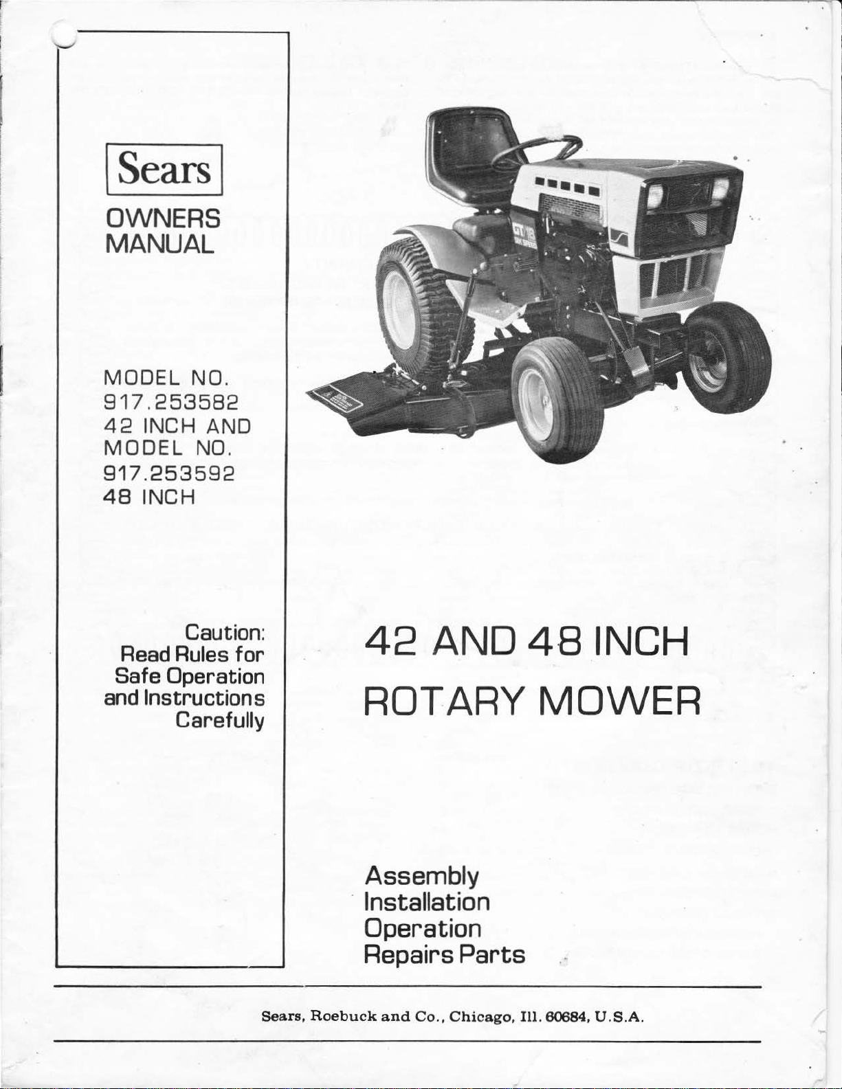
I Sears I
OWNERS
MANUAL
MODEL NO.
917.253582
42
INCH AND
MODEL
917.253592
48
INCH
NO
.
Caution:
Read
Safe Operation
and
Rules
Instructions
Carefully
for
Sears,
42
ROTARY
Assembly
· Installation
Operation
Repairs
Roebuck
and
AND 4·8 INCH
MOWER
Parts
Co.,
Chicago,
Ill.
60684,
U .
S.A.
~ULATI
,l,ower.
give
Should
dy,
They
tools
·~
you
you
please
have
to
service
1
has
the
contact
ONS
been
designed, engineered
best
experience
competent,
your
or
repair this unit.
possible
well-trained technicians
on
your
purchase
dependability
any
problem you
nearest Sears,
of
and
manufactured
and
cannot
Roebuck
a Sears Rotary
performance
easily reme·
and
Co. Store.
and
the
to
proper
Pl
ease read and retain this manual.
enable you to assemble,
properly. Always observe
TION".
operate
the
"RULES FOR
The
and maintain
instructions will
SAFE
your
...,J
mower
OPERA-
ON
FULL
ROTARY
ONE YEAR WARRANTY
MOWER TRACTOR ATTACHMENT
(EXCLUDING BLADE(SJ AND BLADE ADAPTER(SJ
For one year from the date
tained
manual,
and
lubricated according to the operating and maintenance instructions in the owner's
Sears
will
repair free
of
purchase, when this rotary mower
of
charge any defect in material
tractor
or
workmanship .
attachment
is
main-
.
This warranty excludes blade(s) and blade adapter(s), which are expendable and become worn
during
This warranty does
WARRAN
SERVICE CENTER IN THE
is
This warranty gives you specific
from
normal
use.
repairs necessary
to
manual; and
rotary mower
TY SERVICE
in
use
in the United States.
state
to
state.
SEARS, ROEBUCK
not
cover:
, ?'
maintain the
tractor
IS
AVAILABLE
UNITED
AND
because
equ
of
ipment according
attachments
BY
STATES. This warranty applies
legal rights,
CO., Sears
Tower, Dept. 698/731 A, Chicago, I L
operator
used
abuse
or
negligence, including the failure
to
instructions contained in the owner's
for
commercial
or
rental purposes.
CONTACTING THE NEAREST STORE
only
while this
and
you may also have
other
rights which vary
OR
product
60684
TABLE OF
RULES
ASSEMBLY INSTRUCTIONS 2
PRE-USE ADJUSTMENT •
OPERATING INSTRUCTIONS • 6
MAINTENANCE INSTRUCTIONS 7
REPAIR PARTS .
OPTIONAL EQUIPMENT
FOR
ASSEMBLY
GAUGE WHEEL REPAIR PARTS .
CONTENTS
SAFE
OPERATION 1
OF
GAUGE WHEELS
5
11
16
17
RULES FOR
LOOK FOR THIS SYMBOL TO POINT OUT IMPORTANT
SAFETY PRECAUTIONS.
ALERT!
YOUR SAFETY
SAFE
IT
IS
OPERATION
MEANS--ATTENTION! BECO
INVOLVED
.
ME
1. Know
2. Do
3.
4.
5. Keep
6. Do
7. Always get
8. Clear
9.
1
0.
11.
12.
13.
14.
15. Reduce
16. Do
17.
18.
19. Do
20.
21
. Never
22.
the
controls
OWNER'S
adults
Do
tance
Always
clothing
area being
not
hand
and
Disengage all
fore
Disengage
fore
Disengage
spark
ing an adj
Disengage
in use.
Take
attended,
the
brake,
Do
hill. Mow
15°);
vent
when changing direction
a gear low enough
and
to
slow.
Never
sure
Stay
ways.
Exercise special
in
order
deliberately run
object.
Never place hands
(discharge
mower
MANUAL.
not
allow children
to
operate
not
carry
away.
your
not
in drivers
side.
the
thrown.
attempting
leaving
plug wire(s)
all possible
attachments,
not
never across
tipping
not
shifting gears.
or
alert
not
passengers. Keep children
wear
substantial
that
could
eyes
cut.
attempt
seat
on
work
attachment
power
the
power
ustment
power
such as disengaging
stopping
stop
or
up
and
speed
or
shift
gears while going
mow
in
at
a speed which
for
holes
drive
too
to
prevent
shift
gears until
chute)
are
running. Always keep clear
and
how
to
stop
quickly. READ THE
to
it
and
Don't
to
. •
or
area
to
to
operator's
to
or
to
precautions
shifting
the
start
down
the
on
loss
wet
care
tractor
or
operate
without
footwear.
get
caught
mind
let
other
operate
off
your
of
objects
clutches and
start
the
attachments
position.
mower,
from
spark
repairs.
attachments
into
engine,
suddenly
the
face.
slopes and
of
control.
on
to
negotiate
To
reduce speed, move
or
slippery grass, when
could
in
the
close
or
terrain
to
when
the
blades from striking
or
tractor
feet
under
near any moving parts while
the
proper
in
on
your
int
your
tractor
engine.
stop
plug(s) before cleaning,
when
the
and
face
make
slopes.
cause
creeks, ditch
mowing
mower
comes
vehicle. Do
instruction.
and
Do
not
wear loose
moving
which
neutral,
removing
when
up
the
the
parts.
tractor,
erests
tractor
from
and
the
when
power-take-off, lowering
of
slopes
Exercise
or
slope
and
into
mower,
mower
distract
or
the
might
shift
into
stop
the
engine
and
transporting
leaving
the
setting
the
going uphill
(not
turns
gradually
extreme
down slopes. Choose
without
a skid.
other hidden
es
and
around
or
over any foreign
to a stop.
in
of
discharge
not
pets
a safe dis·
you
mower
operators
be picked
neutral be·
engine
disconnect
vehicle un-
the
key.
or
greater
throttle
traction
public high-
fixed
them.
the
deflector
tractor
allow
fitting
and
the
.
when
left
up
be·
mak·
or
not
parking
down
than
to
pre-
caution
stopping
lever
is
un-
hazards.
objects
Never
or
chute.
23. Use care
a. Use
b.
Limit loads
c.
Do
d.
Use
this
24. Watch
25. When using any
material
hicle while in
26. Handle gasoline
a.
Use
b.
Never remove
a
Wipe
c.
Open
fumes
27.
Keep the vehicle
dition,
28. Keep all
mentis
29. Never
a building
Allow
30.
To
reduce fire
or
excessive grease.
Except
31.
cleaner
-
moved. Removal
32.
DO NOT
PER WITH THE EXHAUST SYSTEM. Damaged mufflers
or
spark
ically and replace if necessary.
The
33.
34. Do
35. When using
36. Check
37. Do
vehicle and
ed
for
age
should
equipment.
not
the engine.
a.
Mow
b. Never
is running
Shut
c.
unclogging
d.
Check
frequent intervals.
ration.
not
catcher,
place .
when
only
not
counterweight
owner's
out
toward
approved gasoline
running
up
doors
and
in safe working
store
the
for
or
arresters
damage
change
only
make
the engine
the
Replace
operate
on
pulling loads
approved
turn
for
traffic
operation.
or
spilled gasoline.
are
dangerous. Do
keep
nuts,
the
where
engine
adjustment;
cover
OPERATE
be repaired before restarting and
the
in
if
chute.
the
blade
grass
mowers
drawbar
to
those
you
sharply.
manual.
attachments,
bystanders
with
the
hot
if
the
and
safety
bolts
equipment with
fumes may reach an
to
hazard,
directly over
of
could
attachments
after
the
vehicle with
daylight
a c
utting height
the
operator
off
mounting
catcher
with
the
so
can
Use
care
or
wheel weights
when
crossing
nor
care·
it
is
containers.
cap
of
the
engine,
and
cool
such
striking a foreign
engine governor settings
new bags for
Mower
or
engine
is
not
attachments
devices in place.
screws
condition.
before storing
keep
the
DO NOT
part
WITHOUT A
create
should
or
in good artificial light.
must
when
removing
bags
frequently
without
equipped,
or
using heavy
hitch
points.
safely
control.
when
backing.
or
near roadways.
never direct discharge
allow
anyone
highly flammable.
fuel
tank
fill
the
run in
the
run
the
in good operating
tight
to
gasoline
open
engine free
operate
carburetor
could
create
MUFFLER
a fire hazard. Inspect period-
be
stopped
object,
mower,
adjustment
bolts
proceed
dismount
the
for
proper
for
safety
protection.
either
or
the
equipment.
when
suggested in
near
or
add
fuel
tank
garage ·
engine
be
sure
in
the
tank
flame
in
any
of
grass, leaves
Engine
air intake
a fire
and inspect·
and
operating
or
as
while
to
do
grass
tightness
wear
the
entire
deflector
of
the
ve·
gasoline
the
enclosure.
OR
overspeed
the
so.
catcher
or
indoors.
exhaust
indoors
con-
equip·
inside
or
spark.
if
is
hazard.
TAM·
the
dam-
the
follows:
engine
deterio·
grass
shield
to
air
re-
or
at
in
.
. 1 .

LEVER
PLUNGER
To assemble your
a 9/16"
When
R.H. (Right Hand)
used,
it
steering wheel
tractor
ASSEMBLY
Install
Lift
Lever using:
two
Flat
Washers,
bag
found in
a.
Place
bottom
Weldment
Insta
b.
Be
ha
t
Washers,
curely.
of parts.
Lift
Lever (Fig.
of
Lever outward
wi
th
holes in Lever.
ll
Lift
sure
t Lever fits on end
Lever
Lift
Lever Bracket straddles Lever Quadrant and
Lockwashers and Hex Nuts. Tighten Nuts
Mow
Wrenc
h and a Hammer
means
from
as
if
seat
and facing forward .
two
Lockwashers and
to
end
you
1)
over Lever Quadrant and
to
of Lif
t Shaft Weldment (Fi
of
Lift
er you
or
a position behind
were seated
align Bolts in
Shaft.
L.H.
Secure
will
(Left
two
Hex Nuts
Lift
with
need
Hand)
on
Shaft
g.
Flat
"<.--
is
the
the
tilt
1 ).
se-
1..
c. Depress Lever Plunger and move
Lever Quadrant. Drive Drive Lock Pin through Lever,
Lever Quadrant and
ASSEMBLE
1. Check tractor tire pressure
2. Drive tractor
3. Position mower on R.H. side
4. Turn tractor steering wheel
5. Lock all
6. Move
7. Slide mower under tractor
8.
9.
Lift
directly
Snubber Pull Rod
tween
front
For
ease
long 2 x 4 (or similar object)
mower (Fig. 3).
Move
Lift
10. Grasp suspension arms
suspension arms and
Hanger Brackets.
to
four
Attaching Plungers in the
Lever
beneath Hangar Brackets. NOTE:
wheels.
in attaching mower
Lever
Lift
Lever Bracket.
MOWER
an
area
that
to
to
the extreme rear position.
is
extending
to
the extreme forward position.
by
the Spring Box
align
with
Lift
Lev
TO TRACTOR
for
proper inflation.
is
smooth and level.
of
tractor
the extreme
until
to
to
flat
as
"OUT"
Suspension Arms
front
of
tractor, place a
wise under
holes in
Front
er
to
midd
le
shown {Fig. 2).
left.
position.
are
Be
sure end
tractor
each
es.
Raise
two
and
and
end
of
be-
foot
of
R.H.
Rear
of
..
F•I•G•U•R•E•3••••••••1i2ii
xil4
________
..
11.
12.
13. Repeat st
14. Pull
_ 2 _15.
Release
Front
Release
Hanger Bracket.
Remove Blocks fro m under
front
Plunger
Hanger Bracket.
rear Plunger
eps
10, 11
Lift
Lever back
so
so
that
and 12
to
lift
that
Plunger enters hole
Plunger enters slot in R.H. Rear
for
L.H.
side
of
mower.
mower .
each
end
of
mower.
in
R .H.
FIGURE
4
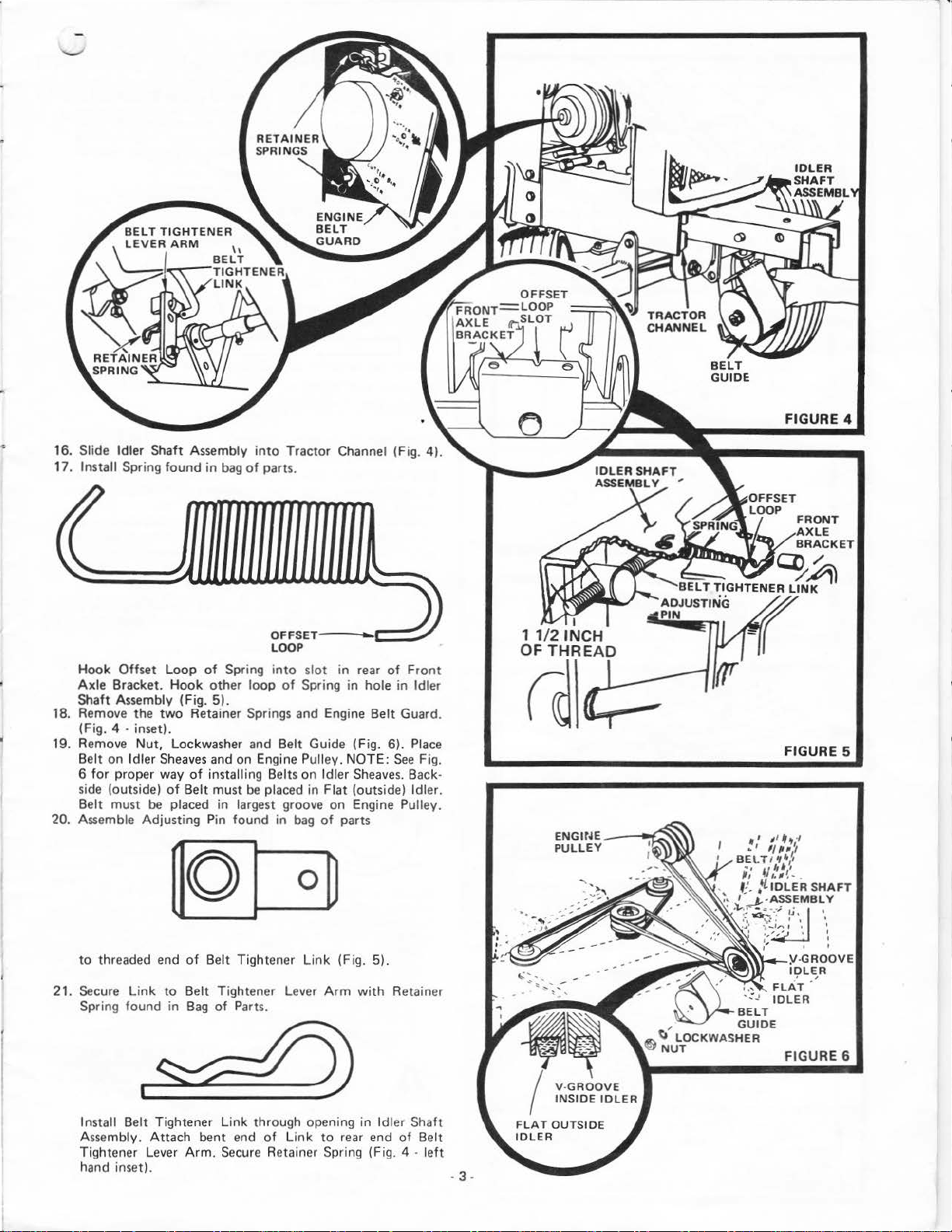
16. Slide Idler Shaft Assembly
17.
Install Spring
Hook
Axle
Bracket.
Shaft Assembly (Fig.
18. Remove the
(Fig. 4
19. Remove
Belt
on
for
proper way
6
side (outside)
must be placed
Belt
20. Assemble Adjusting Pin
to
threaded end
Offset
· inset).
Nut,
Idler
found
in
bag
Loop
of
Spring
Hook
other
two
Sheaves
5).
Retainer Springs and Engine Belt Guard.
Lockwasher and Belt Guide (Fig. 6).
and on Engine Pulley. NOTE:
of
installing Belts
of
Belt must
in
found
of
Belt
into
Tractor
of
parts.
OFFSET·-LOOP
into
slot
loop
of
Spring
on
be
placed
in
in
bag
largest groove
0~
Tight
ener
Link
- .
'---
in
rear
of
Front
in
hole in Idler
Place
See
Idler
Sheaves.
Flat (outside) Idler.
on
Engine Pulley.
of
parts
(Fig. 5).
Fig.
Back-
ENGir~E
PULLEY
--~
FIGURE 5
• I II
··
1
•
1/IU
8El.TIIf•
;;
t/
/.'ll'-
1
. ,
f:'.
,
LtDLER
,.
I
~-ASSEMBLY
.
·":},
~~-;:
I
o,
-'
,"
.,
'
·/
~
',
1
.
SHAFT
~...
·
..
I
21. Secure
Spring found in
Install Belt Tightener
Assembly.
Tightener Lever
hand inset).
Attach
Belt Tightener Lever
Bag
of
Parts.
Link
through opening
bent end
Arm.
of
Secure Retainer Spring (Fig. 4 ·
Link
Arm
to
Link
to
with
in
Idler Shaft
rear end
Retainer
of
Belt
left
FIGURE 6
-3-
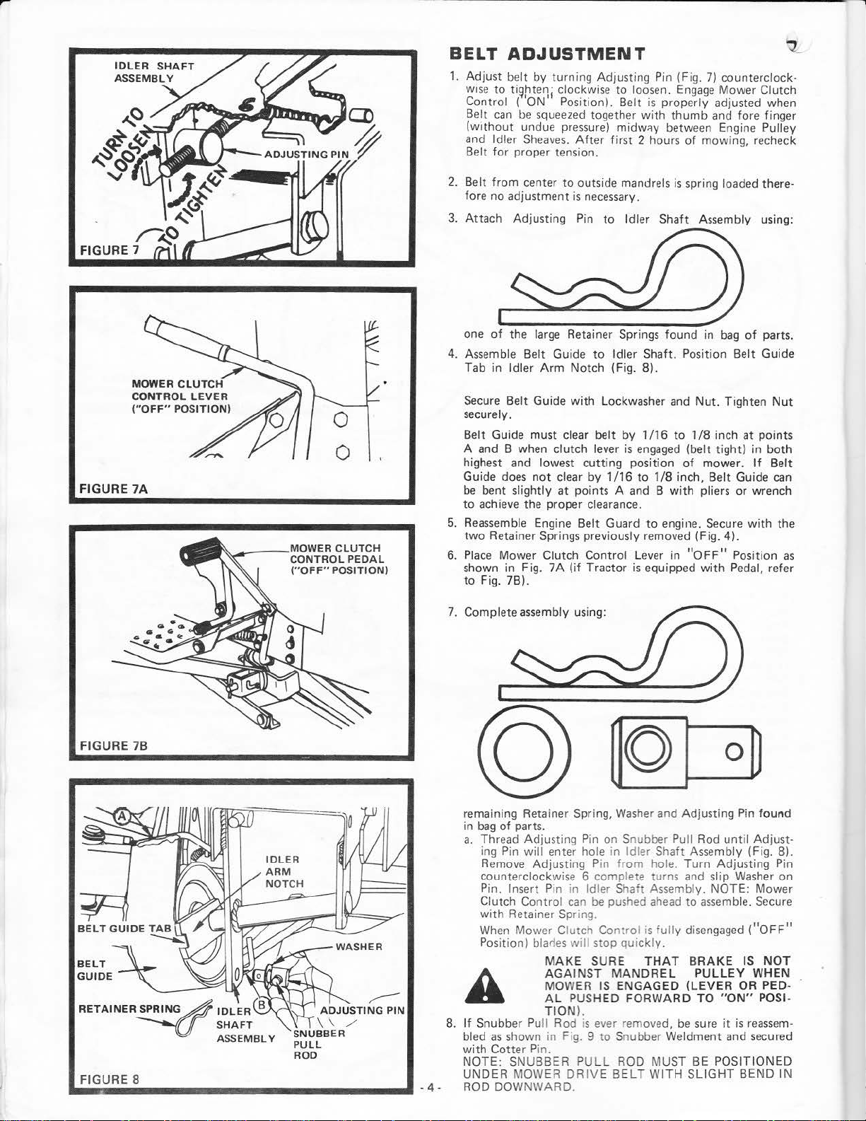
BELT
1.
Adjust be
WISe
Control (
Be
lt
(without
and Idl
Belt
ADJUSTMENT
lt
by t
urni
ng
Adjusti
to
ti~htenj
can
er
fo
r proper tension.
clockwise
'ON'
Position). Belt
be
squeezed together with
undue pressure) midw!ly between Engine Pulley
Sheaves.
After
ng Pin (Fig.
to
loosen.
is properly adjusted when
first 2 hours
Engage
thumb
of
7)
mow
counterclock ·
Mower Clutch
and fore finger
ing, recheck
FIGURE
7A
2. Belt
3.
4. Assemble Belt Gui
5. Reassemble Engine Belt Guard
6.
from
center
to
outsi
de
fore no adjustment
Attach
one
Tab in
Secure Belt Guide
securely.
Belt Guide must clear belt by
A and B when clutch lever
highest and lowest
Guide does
be
to
two
Place
shown in Fig. 7A
to Fig.
Adjusting
of
the large Retainer Springs found in
Idler
bent slightly
achieve the proper clearance.
Retainer Springs previously removed (Fig.
Mower Clutch
7BJ.
Arm
not
de
Notch
with
clear
at
(if
is
Pin
points A and B
mandrels
necessary.
to
Idler Shaft Assembly using:
to
Idler Shaft. Position Belt Guide
(Fig.
Lockwasher
is
cutting
Control
Tractor
by
position
1/16
is
is
spring loaded there-
bag
8).
and
Nut.
1 /16
to
1/8
inch
engaged
to
Lever in
(belt
tight)
of
mower.
1/8 inch, Belt Guide
with
pliers
to
engine. Secure
equipped
"OFF"
with
of
parts.
Tighten
4).
Pedal, refer
at
points
in
both
If
or
wrench
with
Position
Nut
Belt
can
the
as
FIGURE
RETAINER!PRING~IDLER
FIGURE
..
~----------------
78
8
----u
8 UNDER MOWER
SHAFT
ASSEMBLY
SNUBBER
PULL
ROD
ADJUSTING
\\
/
r-
PIN
..
-4-
7.
Complete assembly using:
remaining Retainer Spring, Washer and Adjusting Pin
in
bag
of
a.
A
8.
If
bled
with
NOTE:
ROD DOW
parts.
Thread
ing Pin
Remove
counter
Pi
Clutch Control
with Ret
When Mower Clutch Control
Positio
Snubber Pull Rod
Adju sting Pin on Snubber Pull Rod until
wil
l enter ho
Adjus
clockw
n. Inse
rt
Pin
ainer Spring.
n) blarles
MAKE
AGAINST
MOWER
AL
TION
as
sho
wn
Cotter
in Fig. 9 to
Pin .
SNUBBE R PULL ROD MUST
NWARD.
le
ting P
ise 6 comp
DRIVE BE
in Idler Shaft Assembly (Fig. 8).
in
in
Idler S
can
be
pushed
will
stop
SURE
MANDRE
IS
PUSHED
).
is
ever removed,
from
lete turns and slip
haft
quickl
ENGAGED
FORWARD
Snubber Weldment and secured
hole. Turn Adjusting Pin
Assembly. NOTE: Mower
ahead
to assemble. Secure
is
full
y disengaged
y.
THAT
LT WI
L
be
TH
BRAKE
PULLEY
(LEVER
TO
sure
BE
SLIGHT
0~
found
Adjus
t·
Washer
"ON"
it
is
POSITIONED
on
("OFF"
IS
NOT
WHEN
OR PED-
POSI-
reassem-
BEND
IN
 Loading...