

Page 1
ASSEMBLY, OPERATING INSTRUCTIONS
AND
PARTS
LIST
SEARS
SICKLE
MODEL NUMBER
BAR
FOR
MOWER
917.253120
I Sears J
.
..
SEARS,
SIMPSONS-SEARS LIMITED-CANADA ·
8920H
3.11.62'
ROEBUCK
AND
CO.--U.S.A.; ·
Page 2
1.
Place
2.
Never
3.
Never
touch
4.
Do
engine
5.
Never
fuel
6.
Only
should
7.
Do
before
on
8.
Always
9.
Keep
10. If
11.
12. Wear
13.
14
16,
17.
18.
19.
20.
21.
22.
o
Always
su
Do
. Do
and mower
15.
Never
tractor
Always
removed.
Never
Remove
striking
to
Keep
Always
Do
necessary
declutching
idling
Do
gears.
ing
prevent
your
warning
re it
tractor shi
start
the
refuel
battery. A spark
not
fill
con
persons
not
getting
on
incline
knife
relatively
not
not
run
people
people,
not
speed
not
If
tractor
engine
store
equipment
cool
before
the
on
tonk.
thoroughly
operate
attempt
keep
broke
sharp.
equipment
of
trouble.
replace
is
tight.
mow
crossways
attempt
clutch
leave
machine
or
mower.
keep
all
engine
stones,
rocks
or
property.
drive
olowly
operate
to
stop
to
without
shift
gears
it
is
in motion
tractor
ft lever
engine
storing
fuel
this
to
get
off
tractor. Be
or
hill.
should
thrust
tight
to
clean
lever
shields
inside a building.
wires,
or
roots.
pets
the
tractor
tractor
braking
while
necessary
from
in
when
while
from
with
tonk
while
acquainted
machine
off
or
properly
start
Always
washer
fitting
on
cutter
is
running
and
cans,
Any
and
particularly
over
uneven
in
while
operation.
declutching
going
to
going
"rearing
neutral
anyone
it
is
in a bui l
the
fuel
fuel
in
in
any
enclosure.
the
engine
with
unless
on
adjusted.
clothing,
steep
in
disengaged
boards,
of
high
stop
uphi
up".
properly
tractor
sur e broke
vibrating,
replace
and
lock
slopes
bar,
or
unattended, and
guards
the
above,
ground,
gear
going
NOTE:
, and
up
steep
while
II,
use
SAFETY
and mower
is
near,
and
ding,
con
touching
the
tonk
is
the
rules
supervised.
when
mower
is
on
stop
the
ports
showing
nut
when
and
always
because
to
otherwise
position.
in
place.
branches,
if
struck
children
on
hills
going
down
down
hill,
The
this
procedure
hills.
going
up
one
of
PRECAUTIONS
clutch
and
inside
hot,
securely
of
remove key from
Mower
bones
away
enginP.
Choose
hill,
the
lever
never
ploc e hands
always
the
battery
a bui ld ing
and
wipe
of
safe
is
engaged
and
engine
keep
do
lowest
and
excessive
replacing
hands,
danger
clean, adjust,
or
tractor
and
other
by
the
from mowing
and
curves
hill,
and do
so
quickly
produces
is
recommended
a low
do
so
gears,
in
rear
when
terminal
where
off
any
operation
and
shift
check
wear.
knife,
feet
of
tra
ctor
must
foreign
knife,
to
prevent
not
to
cons
enough
quickly to
reduce
or
disengaged
or
feet
refuel
ing
could
fumes
gasoline
should
tractor
transmission
for
damage
and
check
or loose
tipping
or
repair
ignition
may
area
turn
prevent
gear
switch
never
objects
damage
when
tipping
sharp
iderable
before
to
prevent
engine
position
near
cutter
engine
be
engine
fitting
tractor
applying
climb
be
cause a fire.
may
reach
that
might
permitted
is
into
low
or
loose
lock
nut
clothing
over.
machine
to
be
ope
rated
from
area
knife
or
mowing
of
tractor.
corners
from
braking
hill
tractor
speed
and
bar.
careful
on
open
hove
to
use
running.
or
reverse gea
ports.
at
frequent
away
before
prevent
with
before
guards
with
while
picking
action
brake.
without
rolling
engage
before
that
fuel
flame
been
mower,
Wait
Vi
brat
intervals
from
stopping
children
any
shields
each
and
may
your
sickle
going
down
up
when
throttled
slopping
backward.
clutch
starting
con
or
spilled.
and
until
knife
r,
ion
is
mowing
tractor
from
mowing.
cause
hi II. If
speed
and
When
gradually
engine
does
spark.
Replace
no
minor
stops
especially
generally
to
make
belts.
engin
starting
or
guards
Avoid
injury
bar
mower.
it
during
bock
shifting
start-
not
Let
is
the
to
to
.
...
e
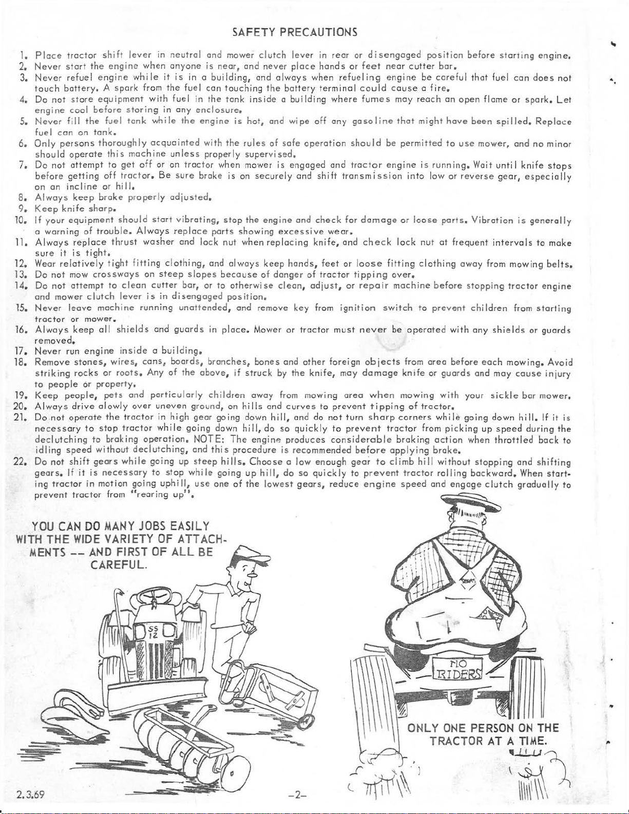
YOU
CAN
DO
WITH
THE
WIDE
MENTS --AND
MANY
VARIETY
JOBS
FIRST
OF
OF
EASILY
ATTACH-
ALL
BE
CAREFUL.
2.3.69
-2-
ONLY
:~~\)
ONE
PER
TRACTOR
SON
ON
THE
AT A Tl
ME.
~i
)
..
Page 3
INTRODUCTION
.•
Setting
Precautions
beginning
beginning
refers
when
L.H.
to
(or
Cut
NOTE:
of
Up,
should
to
of a
to
an
otherwise
(Left
Hand)
mean from a
direction
all
ports
wires.
The
must
of
two
Operating
assemble
paragraph
arrow
stated.
are
position
travel).
ext
ra
be
saved
be
your
in
used,
thick
Instructions
studied
in
the
When
behind
for
very
mower. A number
the
following
adjoining
R.H.
it
shou
and
flat
washers
use
in
and
closely
instructions
figure,
(Right
ld
be
facing
found in bog
Step
Safety
before
at
except
Hand)
and
understood
the
mower
14,
page
the
5.
FIG. 2
•••••••••••••••••••••••••••••••••••••••••••••••••••••••••••
BEFORE
ALWAYS
OR
FIELD
CONSIDER
WEEDS,
OF
TERRAIN
AS
WELL
TRASH.
CERTAIN
AS
OUTLINED
MOWING A NEW
STOP
FOR
HAY,
ALSO
ETC.
TO
BEST
THE
ANALYZE
MOWING
TO
(LEVEL, HILLY
AS
THE
PRESENCE
EACH
CONDITION
ADJUSTMENTS
IN
THIS
MANUAL.
PLOT
HEIGHT
BE
MOWED,
WILL
OR
PRECAUTIONS
OF
GRASS,
THE
LAWN
PROCEDURE.
OF
GRASS,
TYPE
OR
PITTED),
OF
ROCK
OR
REQUIRE
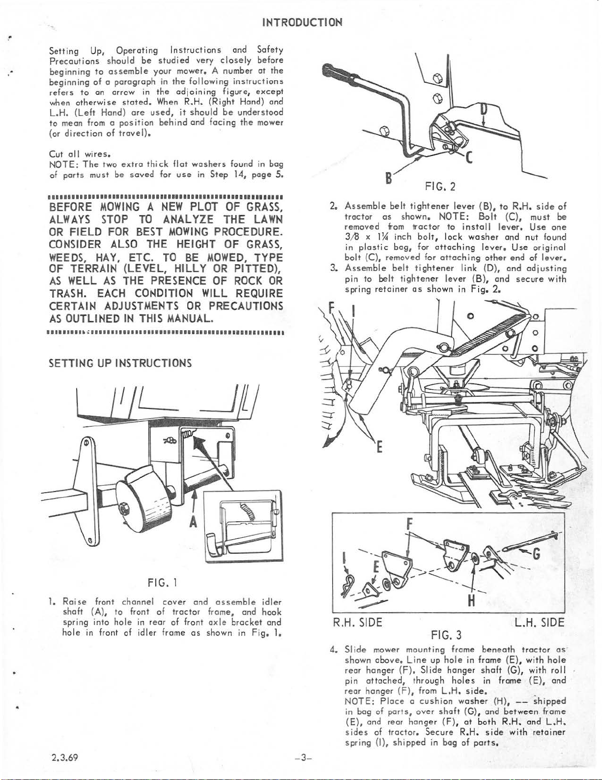
2.
Assemble
tractor
removed
3A3
in
bolt
3.
Assemble
pin
spring
x
1~
plastic
(C),
to
belt
retainer
belt
tightener
os
shown. NOTE:
from
tractor
inch
bolt,
bog,
for
removed
belt
for
tight
tightener
as
to
lock
attaching
attaching
ener
lever
shown
lever (B),
Bolt
install
washer
lever.
other
link
(D),
(B),
in
Fig.
to
(C),
lever.
and
and
2.
R.H.
Use
end
and
secure
side
must
Use
one
nut
found
original
of
lever.
adjusting
with
of
be
•••••••••••••••••••••••••••••••••••••••••••••••••••••••••••
SETTING
1.
Raise
shaft
spring
hole
in front
2.3.69
UP
INSTRUCTIONS
front
channel
(A) ,
to
front
into
hole
in
of
idler
FIG. 1
cover
of
tractor
rear
of
frame
and
front
as
assemble
frame,
axle
show
and
brocket
n in
idler
hook
Fig.
and
1.
-3-
F
R.H.
SIDE
4.
Slide
mower
shown
rear
pin
rear
NOTE: Place a cushion
in
bag
(E),
sides
spring
above.
hanger
attached,
hanger
of
and
of
(1),
mounting
Line
(F).
(F),
ports,
rear
hanger
tractor.
shipped
through
Slide
from
over
Secure
FIG. 3
frame
up
hole
hanger
holes
L.H.
shaft
(F),
in bog
in
frame
side.
washer
(G),
at
both
R.H.
of
ports
beneath
(E),
shaft
(G),
in frame
(H),
and
between
R.H.
side
with
.
L.H. SIDE
tractor
with
--
and
as
hole
with
roll
(E),
and
~hipped
frame
L.H
retainer
.
Page 4
SETTING
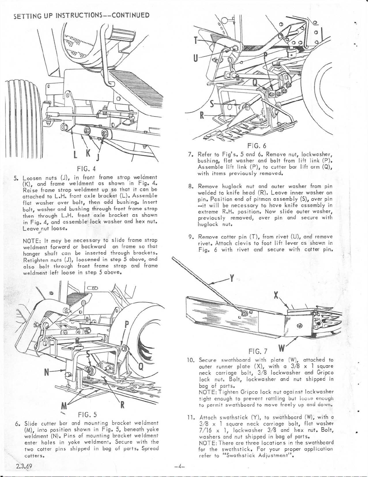
5.
Loosen nut s
(K),
Raise
attached
flat
bolt,
then
in
Leave
NOTE:
weldment
hanger
Retighten
ol
weldment left loose
UP
and
frame
washer
washer and
through
Fig.
4,
nut
>I'
It may
shaft
so
bo It
frame
to
and
loose.
forward
nuts
INSTRUCTI
FIG. 4
(J),
in front fr
weldment
strop
weldment
L.H.
front
over
bolt,
bushing
L.H.
front
assemble· lock
be
necessary
or
con
be
(J),
loosened
through
front
in
ONS--CO
ame
as
shown
up
axle
brocket
then
odd
through
axle
brocket
washer
to
backward
inserted
in
frame str
step 5 above.
NTINUED
strop
we ldme
in F ig.
so
that
it
con
(L).
Ass
embl e
bushing. Insert
front
frame
as
shown
and
hex
slide
frame
on
frame
so
through
step 5 above,
op
brackets.
and
nt
4.
be
strop
nut
strop
that
and
frame
FIG. 6
7.
Refer
to Fig's. 5 and
bushing,
Assemble
with
8. Remove
welded
pi_
n. P_osition
••
It
extreme
.
previously
huglock
9.
Remove
rivet.
Fig
items
wdl
. 6
flat
lift
huglock
to
knife
be
R.H.
nut.
cotter
Attach
with
washer
link
previously
end
necessary
position
removed,
pin
clevis
rivet
6.
Remo
and
(P), to cutter
removed.
nut
and
head (R).
of
pitman
to
. Now
over
(T), from
to
foot
and
ve
nut
bo lt from 1lift
bar li
outer
wash
Leave
hove
secure
ass
embly (S),
knife
slide
pin
rivet
lift
lever
inner
outer
and
(U),
with cotter
lockwoshe
link (P
ft arm {Q),
er from
washer
over
assembly
washer
secure
and
remove
as
shown in
r,
).
pin
on
pin
in
with
pin
.
FIG. 5
6. Slide
cutter
(M), into
weldment
enter hol
two
cot!
cotters.
bar
position
(N).
es
in
er
pins
and
Pins
yoke
shipped
mounting brocket
shown
in
of mounti
weldmen
in bog
Fig.
ng
5,
beneath
brocket weldme
t. Secure with t
of
ports. Sp
2.3.69
weldment
yoke
nt
he
read
-4-
10.
Secure
outer
neck
lock
bog
NOTE:
tight
to
11.
Attach
3/ 8 x
7/16 x 1,
washers
NOTE: There
for
refer
FIG. 7
swothboord
runner
carriage
nut. Bolt, lockwosher
of
T i
e~ough
perm1t
the
to
plate
ports
.
ghten
to prevent
swothboord
swothstick (Y),
1
squa
lockwo
and
nut
ore
swothstick.
"Swothstick
bolt
Gripco
re
neck
shipped
three
with
(X), with a
, 3/8
sher
X
w
plate
lockwosh
and
lock
nut
against
rottl
ing
to
move
freely
to
swo
th b
carria
ge
3/8
and hex
in bo g of port
I o
cot
ion s in t
Fo
r your
Adjustment" .
prope
(W), attached
3/8
x 1
square
er
and
Gripco
nut
shipped
lockwosher
but
loo:.e
enough
up
end
down.
oord (W)
bol
, with a
t,
flat washer
nut.
s.
he
swothboord
r a p
plicatio
to
in
Bolt
'
n
Page 5
1
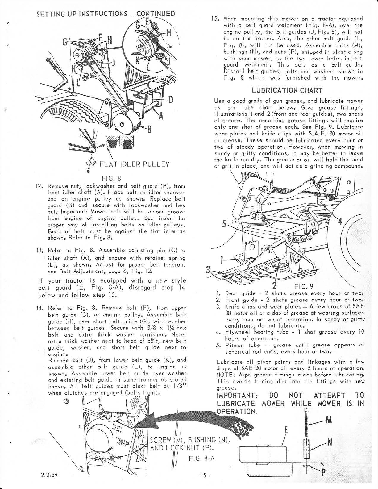
5.
When mounting
with a belt
engine
be
Fig.
bushings
wit h your mower,
guard
Discord
Fig
on
. 8
pul
the
8),
this
guard
ley, the
tractor. AI
wil
l n
ot
(N),
and nuts
weldment.
belt
guides, bolts and
which
was
mower on a tra
weldment (Fig.
belt guide
so,
be
to
the
This
s (J, F
the other belt
used.
furn
Assemble
(P), shipped
two lower
acts
as a
ished
washers
ig.
with
ctor
8-A),
8),
in
plastic
holes
belt
the
equipped
over
the
will
not
guide
(L,
bolts (M),
bag
in
belt
guide.
shown in
mower.
12.
Remove
front
and
guard
nut.
from
proper
shown.
13.
(D),
see
If
belt
below
l4.
guide {H),
~-111
nut,
i
dler
shaft (A).
on
engine
{B)
and
Important: Mower
engine
way of
Back
of
belt
Refer
Refer
to
F i
idler
shaft
as
shown.
Belt
Adjustment,
your
traG
tor
guard
Refer
belt
between
bolt
extra
guide,
engine.
Remove
assemb
shown.
and
above.
when
and
follow
to
guide
and
thick
washer,
bolt
le
Assemble
existing
All belt gu
clutches
(E,
Fig.
over
belt
extra thick
other
' \
{:;;
FLAT IDLER PULLEY
()
lockwosher
pulley
secure
of
engine
instal
must
to
Fig.
g.
8.
Assemble adjus
{A),
and
Adjust
is
equipped
Fig. 8-A),
step 15.
8.
{G),
at
short
gui
des. Sec
washer
and
(J),
from
belt
belt
gui
ore
engaged (belts
~
FIG. 8
and
belt
Place
belt
as
shown.
with
lockwasher
belt
wi
II
pulley. See
ling
belts
be
against
8.
secure
page
with retain
for
proper
6,
Fig.
with
disregard
Remove
engine
nex
lower b
de
ides
bolt
pulley.
belt
guide
ure
with 3/ 8 x
washer furnished.
t to
head
short
belt
lower belt
guide
elt
in
some
must
(L),
clear
~
guard
on
idler
Replace
be
second
on
idle
the
ting
belt
12.
a new
(F),
Assemb
(G), with
of
b~lt,
guide
gui
to engine
guide
manner
belt
ti
(B), from
ins
r pu
flat
pin (C)
er
from
de
over
as
),
sheaves
belt
and
groove
ert
lle
idler
spring
tensio
style
step
upper
le
washer
1)4
Note:
new
next
(K),
washer
stated
by
l/8"
hex
for
ys.
as
to
n,
14
belt
hex
belt
to
and
as
LUBRICATION
Use a good
as
per
illustrations 1 and
of
grease.
only
one
wear
or
grease,
of
two
sandy
the
knife
or
grit
l.
Rear
2.
Front
3.
Knife
30 motor oi I or a
every
conditions,
4.
F lywheel
hou
5. Pitm
spherical rod
Lubricate
drops
NOTE: Wipe grease fittings
This
greas
IMPORTANT:
LUBRICATE
OPERATION
grade
lube
The
shot
plates
These
steady
or
gritty
run
in
place,
guide
guide
clips
hour or
rs
of
an
tube -grease
all pivot
of SA E
ovoids
e.
of
chart
2 (front
remaining
of
grease
and
knife
should
operation.
conditions,
dry.
The
and
" 2
• 2
a~d
two
do
not lubricate
bearing
operation
ends,
30
motor oi I
forcing
MOWER
.
gun
grease
wi
shots
shots
wear
dab
.
points
DO
grease,
below.
each.
clips
II
oct
plates-
of
of
tube
every
dirt
CHART
and
Give
and
rear
grease
be
However
operation.
fittings
See
with
lubricated
it
may
or oil
as a grinding
grea
se
grease
grease
.
• 1
shot grease
unt
il
hour
and li
eve
ry 5
clean
into
the
NOT
WHILE
lubricate
grease
guides),
wi
Fig.
9.
S.A.E.
A few
30
every
, when mow i
be
better
wi
II
hold
compound.
every
hour or
every
hour
drops
at
wearing surfa
In
sandy
grease
or
nkages
hours
before
appears
two.
with
of
lubricating.
fittings
ATTEMPT
MOWER
mower
fittings,
two
shots
II
require
Lubricate
motor
oil
hour or
ng
in
to
leav
the sand
two.
or
two,
of
SAE
ces
or
gritty
every
10
a few
operation.
with
new
TO
IS
IN
e
at
2.3.69
FIG.
~
8-A
- 5-
Page 6

OPERATING
For
each
job
the
ground
In
thin
may
be
cases,
heavy
lower
engine
which
run
engine
reduce
DO
MOWER
CAUTION:
possible
knife.
above
It
is
area
types
sti
cks,
represent
operator,
assemble.
mowing,
while
NOTE:
ning
TO
TRANSPORT
trav
stan
ds
inc
reased
the
engine
blue
grass
gear
at o higher
seems
throttle
wear
NOT
ATTEMPT
IS
Run
to
reduce
Operating
level.
the
respon
where
to
the
of
foreign
cons, bottles,
potential dangers
and
Always
and
unattended.
Sickle
move
INSTRUCTIONS
of
mowing
e l
speed
of
(shift
(slower
to
do
and
vibration.
it may
it
with
material
to
may ol so
ground
speed.
the
best
ot
slower
be
Pick
TO
IN
OPERATION.
engine
angle
s ibi I ity
sickle
material.
ore
never
bar
through
vibration
of
of
bar
certain
be
on
leave
must
be
material
at
cutter
the
will
pipe,
the
the
wi
II
be
necessary
each
plot
the
ground
a higher
gear)
be
throttled
necessary
travel speed)
gear
and
job
of
spee
ds
LUBRICATE
reduced
and
wear
bar
not
operator
be
used
This
includes
rocks, etc.
to
the
to
damage
alert
for
sickle
in
operation
to
be
cut.
to
be
travel
and
to
engine
mowing.
if
possible
speed
on pitman
to
exceed
to
see
is
free
wire,
sickle
obstacles
bar in
before
to
vary
mowed.
speeds
in
most
bock.
shift
to
and run
speed
Always
WHILE
whenever
and
35°
that
the
of
all
rope,
These
bar
and
the
knife
when
operation
begin·
In
to
SWATHSTICK
ADJUSTMENT
·.
a
FIG.
11
There
adjustment.
hole
BELT
are
three
hol
Adjust
for
higher
weeds.
ADJUSTMENT
es
in
swothboord
to
best
turn
---
crop
......
for
being
swa
thstick
cut. Lower
\
I
I
I
I
Stop
until
Fig.
strop
tractor
latch
10.
Secure
(C).
engine.
brocket
bar in
FIG.
Depress
(B)
10
con
be
upright
on
foot
positioned
position
lift
as
with
lever
shown
tra
nsport
(A)
in
Turning
belt.
adjusting
directi
to
requires
(pu
that
to
in
the
Remove
on
tighten
a
sh
forward),
slip
wear
prevent
adjusting
STORAGE
Before
thoroughly
surfa
rust
clean
storing
ces
should
preventive
, dry
adjusting
retainer
pin
(A,
(when
belt.
fair
amount
when
out
premature
pin.
mower for
clean
be
especially
area.
---
--
FIG.
pin
(A,
spring
Fig.
12),
standing
Belt
rapidly.
away all
given o good
in
tightener
of
belt
is
Keep
failure. Replace
any
the
_,
12
Fig.
(D,
in o
front
effort
properly
belt
long
dirt
and
mower
.,
- v
12),
adjusts
Fig.
8),
and
counter-clockwise
of
the
tractor),
lever
(B,
Fig.
to
engage
adjusted.
properly
retainer
period
debris.
coot
of
knife.
Belts
adjusted
spring
of t
Wearing
grease
Store in a
the
turn
2},
lever
ime,
or
2.3.69
-
6-
Page 7

MAINTENANCE
AND
SERVICE
INSTRUCTIONS
DAILY
Ma
Keep
TO
1. Pos
2. Re
MAINTENANCE
ke
sure all nuts
mow
er lubric
REMOVE
ition
knife
move
hug
ossemb
with new
ly
KNIFE
lock nut
out from the
kni
fe. Adjust kni
KNIFE
A
dull knife, imprope
make
good
cutting
Guards
Align
choking
or
Remove
where
the clip just begi
wea ring pl
clip
hoi d the
these
led
bent,
nece
. When
wearin
ore
often
ger p
lates
may
result.
the po
the knif
ssary. After
ates
the
front
of the
g p
ints
that
plates
lotes.
on
bol
ts
ore tig
ht
and cotter
ate
d.
in
the extreme
and
rly
adjusted kni
impo
ssible.
knocked
by
striking thick portion of guard
Properly adjusted knife clips
of the knif
e;
sight
along
the
ns
to tighten
support the bo
become
knife
down
are inexpensive
out position
outer wash
L.H.
end of
fe
cli
Make
out
of
e wi
the
knife
ha s b
dow
worn,
on the
er
bar. Shar
ps
as
fe
clips, bent
the
I ine
by strik ing stones and
ll
rise
bock
een
n on
ck edge
the
guard
and
pins
spre
ad.
(knife
from
stated belo
following adju
when
and if bent,
straightened, adjust the
the
of
back
edge
plates.
should
farthest
pin
welded
pen
knife sectio
w.
guards
keep
cutting
knife
the
kni
of the
bereploce
or
stments bef
wit h o hammer. Do
the
and results
straighten
secti
fe soon bec
knife
Even though the knif
to
on.
Keep kni
away from tractor
worn
kni
d wh
fe sh
kni
fe
head.
ns.
Repair
wearing
ore each
obstructions.
fe
flat upon the ledg
in
pulling
it
carefully
knife clips.
If the
omes wor
is not
enev
er
mower
supported
badly
arp
and t
rue.
).
Slip pitm
pla
day's
not benc;llips
n.
e c I ips
an from pin and pu ll comple
or
str
aigh
tes
will
cutti
Remove
er
or
tearing
on f
loor
Tap
is
used
The
wear
high
hove
worn.
Obse
rve
ten kni
abs
ng.
knife and
plates.
or
it
with
in
enough.
been
fe
orb o great
of guards down
If
instead
block
by
light
loose
abrasive
plate
is
This
set
down
all
safety precaution
te
as
needed, or
deal
sight
through
above knife,
the clips become l
of o sh
striking wit
blows
of
soils, the
located
under the
makes
as out I i
of
pow
earing
hammer
it
difficult
ned
rep
guards.
action.
h hammer
s.
kni fe
lace
er and
as
oose
unt
steel
knife
above,
il
to
PITMAN
Tigh
ten
to
obta
Tighten
The
above
the
top
or
derin
g rep
A
ll
ports I is
ordering
f
urn
i shed
WH EN
REPLACEMENT
hex
jam n
in this
hex
uts (A),
dimension. Spherical
jam
nuts
and
securely.
SEARS
number
of the frame
air
ports
on
ORDERING
is the
Model
weldment.
port
s.
ted herein may be ord ered
by moil from t
request
or
ports
REPAIR
B
spherical
rod
SICKLE
Number
Always
he
moil order house
will
be shipp
PARTS,
FIG
. 13
rod
ends
(B),
ends
must
HOW
TO
ORDER
BAR
MOWER--
of
your
SEARS
ment
ion
the
Model
through
ed at
ALWAYS GIVE
SEARS, ROEBUCK
which
prevailing
in
be
pitman
at
SICKLE
THE
tub
e (
C),
until
90°
to
each other
REPAIR
MODEL
Number
serves
prices
FOLLOWING INFORMATION
BAR
of
the
and
PARTS
NUMBER
MOWER.
your
mower
AND CO.
territory
you
will
on
equal
with
zerk
917.253120
It
wi
II
when
or SIM
in
which
be
billed
amount
fitting
be
communicating with u:;
PSONS-SEARS LIMI
you live,
accordingly.
found
AS
of
threads
facing
on a
selling
SHOWN
ore
to
rear
plate attach
TED
prices
IN
THIS
exposed
of
mower.
or when
. When
will
LIST;
ed
to
be
1.
The
PART
NUMBER.
2.
The
PART
NAME.
Each port
the Key
SEARS, ROEB
change
letter
s or
has
been given 0 K
or
number
UCK AND CO. and S
imp
rovements
when ordering
witho
ey letter or
ut
imposing any obi igot
repair
IMPSON
number
ports.
S-SEARS
which
LIMITED
ion
to
3.
4.
is
install
T he
The
used
MODEL
NAME
reserves the
the same up
only
NUMBER··
of
OS
Implemen
a
guide
right
on
its
917.253120.
t · · SI
to
find
to make
products
CKLE
the
any
heretofore
BAR
part
number.
changes
MOWER.
Do
in
design
manufactur
not
use
and
ed
•
Page 8

SEARS
SICKLE
BAR
MOWER --MODEL
NUMBER
917.2531
20
8
c
/
c
'
'
'
/
/
/
/
/
M
' i
2.3.69
N 0 P R
49
©4
7
@
~48
~
'511
' 1
---
---
-8-
FOR
NEW
REFER
I J l
rt
@ ©
@43
44
®
STYLE BELT
TO
PAGE
i46
@41
tt::h42
~
GUARD--
5,
FIG.
8-A
v
S:l
~
47
f'Al
~48
®
Page 9

SEARS
SICKLE
BAR MOWER --MODEL
NUMBER
917.253120
KEY
NO.
-9
10
13 528
15 606A287
22 634A301
-
PART
NO. NO.
1 5309H
5235H1 Frome Hanger Shaft 37 272232 *Hex
2
3 5304H
5280H
4
131016 *Washer,
5
1554H Timken
6
6855M
7
?A
634A287 Frome Weldment with Bearing
8
2623M
606A286 Frome Strap Front Weldment
11
120388 *Washer,
12
5277H
2H
14
5249H
357H Huglock Nut 50 103384
16
19151616 Washer
17
18
19211612 Washer
5310H
19
1553H
20
21
9244H
2H
924
21A
278H
23
24 7939M
25
26 606A290
27
28
29 5234H
30 120394 *Washer, 13/ 32 x 13/ 16 x 16 Ga. M
31
32
33
34 5296H
35 5237H
35A 32
35B 122181
124944
6523H
634A286 Foot
1542U
5252H
606A278 Yoke Weldment
24M
DESCRIPTION
Cushion
Elastic
Dust
Grease
Model Number
Bushing
Bushing
Flywheel
Flywheel Guard
Belt
Grease Retainer
Timk
Spherical
Pitman
Flywheel
Grease Fitting
Bushing
*Nut, Hex Jam ASF 5/8-
Plated
Transport
Bushing
Clev
Spring
Cutter
Lift
Pull
Bushing
Bolt,
*
Washer 36 120389 *Washer,
Stop
Nut
5/8
• 18
Cop
21/32
x 1-5/ 16 x 13 Go.
Cone
Fitting
Plate
Cups
Flat
7/16
x 1 x 14
Guard
Bracket
Guide Weldment • Flywheel 49 120390
15/
32
x 1 x 12
21/32
x 1 x 12 Go.
Washer
en
Cup
Rod End
Tube
Assembly
Stop and Rivet
Lever
Wel
dment
is
Bar
Latch
Link
Rod 8920H
Hex
3/8
• 16 UNC x 2
Ga.
Ga.
18
UNF F 120696 *
}1
Plated
KEY
38
39
40
41
42
43
44 219431 *Hex
45
46 120388 *Washer, 7/ 16 x 1 x 14 Go.
47
48 219434
51
52 347H
53
- A
B 1572H
c
.--.o
E
G 122007 *
H
I 120696 *
J
L
N 122472 *
0 5297H
p
R 103408
PART DESCRIPTI
NO.
Nut,
131016
121574 *Lockwosfier 5/ 8
219436 *Hex Nut, 5/ 8 -
131099
120377 *H
120214 *
120393 *Washer,
120384 *
8238H
132295 *Machine Screw, Slotted Fill
4940M
122333 *Bolt, Hex
428691 - *
122145 *Bolt,-Hex 3/
122017 *
120233 *
122491 *
103384 *
456723
*Wash
er,
Cod.
*Lockwosher, 3/8
ex
Nut,
Lockwosher, 5/1
Nut,
Cad
. P
Lockwasher
Hex
*Nut
1
*Wash
er,
*
Cotter
Split Spacer
Hug lock Nut
~~
•
20
Retainer
Roll
Pin
Bolt,
Bolt
, Hex 5/ 16 • 18 x 2
Bolt,
Bolt,
Bolt,
Bolt,
Bolt,
Cotter
Bolt
, Hex
Drilled
*Cott
er
*Cott
er
Instruction
ON
}S
x
114
x 14 Go.
7/16
- 14
21/32 x 1-5/16
Plated
Cod.
11
Cod.
3/8-
16
6
5/16
• 18
11/3
2 x
11/16
lated
,
Y7
Cad.
Y7
- 13
Cad.
9/ 16 x 1-3/ 8 x 12'
Pin,
1/8
x %
UNC
x 3
14
Plated
Spring
7/16-
Hex 5
Hex
5/16
Hex 5/16Hex 5/ 16 - 18 x 2
Hex
3/8Hex
Y,
Pin,
Y7
Rivet
Pin
Pin 3/16
/8 • 11
8-
16 x 1
• 18 x %
16 x 1
• 13 x 3
1/8
x %
• 13 x
3/1
6 x 1
and
Parts
14 x 3
18 x 1
x 1
x 13 Go.,
Plated
Plated
x 16 Go.
Plated
Plated
x 2
Cad. Plated
14
14
Cad.
Cad.
14
14
2}1
14
Book
Ga.
ister
Hd.
Plated
Plated
3.11.69
-9
* Standard Hardware Item-·
Purchase
Locally
.
-
Page 10

SEARS
SICKLE
BAR
MOWER--MODEL
NUMBER
917.25l120
c
T
D
y
·~::::::::::::::::::::::::J~
I
~M
p__
P
--
1 I
~.....-49
~~48
1
~
--.J
I
---
y41
v
I
N
~-----48
Page 11

SEARS
SICKLE
BAR
MOWER
--MODEL
NUMBER
917.253120
KEY
NO. NO.
10
11
12
13
14
15
16
17
18
19
20
21
22
23
24
25
26 4569M 1 Wearing
27
28
29 606A280
30
31
32
33
34 6842M
35
36
37
38
39
PART
1 4379H Shift Handle Grip
634A 123A
2
3 6508H
4 6499H
5 4940M Retainer Spring
6
6501H
7 4301H Spring
8 606A294A
9 606A296
697H
5386H Bushing
606A295
12
0395 *Washer,
272233
4775H
5308H
4939M Retainer Spring
1689E Bushing 5
120214
219431
120382
219432
19141610 *Washer,
5232H
634A300
4572M
575X31
5311H
5285H
5290H Rear Guide
357H
1915161
19211612 Washer
634A299A
606A252
120383
DESCRIPTION
Lever
Lever
Belt
Tightener
Adjusting
Idler
Idler
Bearing
Idler
*Nut,
Hex
Belt
Guide
Y·Belt
*Lockwasher,
*Nut,
Hex 5/
*Lock
washer 1 3;13
*Nut 1 Hex
Swa
th
Knife
Knife
Knife
Cutter
Wear
Knife
Nut,
Huglock
Grease
Washer
6
Knife
Belt
Guide Weldment
*Lockwasher,
Weldment
Stop Strap
Pin
Shaft
Assembly
and
Bearing·
and Bearing • Outer
Flat
7/16.
(Engine
16 • 18
3;13 • 16
Flat
stick
Assembly
Plate
Clip
Sections
Bar and Mounting Bracket
Plate-
Head
Spacer·
Fitting
15/32
21/32
Head and
KEY
NO.
40
41
42
Link
Inner
43
44 5254H
45
46
47
48
49
so
51
15/32
x 1 x
12
Ga.
20
UNF
to
Flywheel)
5/16
C.P.
Cad. Plated Cad.
Cad. Plated
Cad. Plated
7/16
x 1 x
10
Ga. F 6801M
Only
(Box
of
25)
Rear
Rear
x 1 x
12
Ga.
x 1 x
12
Ga. Cad. Plated
Pin
-Front
7/16
52 120388 *Washer,
53 5394H
54
A 122040 *
B
c 122145
D
E 5480H
G
H 126402
J
K 6800M
L
M
N
0
p
-Q
R 120915
s
PART
NO.
5312H
5289H Front Guide
5284H
5247H
5248H
5256H
5233H
57SX32 Guard
575PA53
606A273 Outer Runner Weldment
606A292 Swathboard Assembly
120380 *Lockwasher,
180124
144531
120918
101536
103419
120915
126411
6802M
101535
120915-
123316
DESCRIPTION
Knife
Head
Plate
Knife
Head Spacer •
Wear
Plate·
Wear
Front
Knife
Back (Only)
Inner Runner
Inner Runner
Plate
Double
Nut,
Gripco
Bolt,
Hex
Bolt,
Hex
H.
T. Cad.
Bolt,
Hex
Plated
*Machine Screw,
Rivet,
Rivet,
Bolt,
*
*Bolt,
*
*Cotter
*
*
*Bolt,
*Bolt,
*Bolt,
*
Hex
Hex
Bolt,
Sq. Neck
Rivet,
Bolt,
Sq. Neck
3/8 • 16
Bolt,
Sq. Neck Carriage
3/8 • 16 X 1Y2
Rivet
CTSK #8 x
Sq.
Sq.
Sq. Neck Carriage
Cad.
Plated
Bolt,
Hex
Front
Plate
Divider
(Box
Guard
Flat
7/16
'!1.1
5/16 • 18 x 1Y2
3;13 • 16 x 1'!1.1
Plated
3/8
Flat
Head
Round Head
3/83;13- 16 x
Round Head
Pin
, !4 x 1
X 1
Neck
Neck Carriage
'!1.1 • 28
Front
Base
of
25)
Assembly
x 1 x 14 Ga.
·16
x 1
'!1.1
Truss
7/32
5/32
16
x 1
Y2
1'!1.1
Plow
3/8 • 16 x 1'!1.1
5/32 x 9/16
'!1.1
Carriage
1·1/8
Plow
3;13 • 16
x
Y2
Grade
H.T.
Hd.
'!1.1
- 20 x Y2
x%
Bag
of
3
x 13/16 Bag of 5
Bag
Bag
of
20
x 1
3/8-
16
x 1
3/8 -16
x 1
of
35
*Standard Hardware Item --Purchase
3.11.69
Locally
-11-
Page 12

--
~-
~~
~
KEEP
C~ILDREN
PETS
AN
A\JAY
___
_
CLEAR
AREA
BEFORE
REMOVE
OF
RUBBIS~
MOW'
THE
IGNITION
THE
I
NG
__
_
KE"l
__
FUEL
LEFT,
2.3.69
FROM
CAREFULLY
T~E
-12-
Page 13

SUPPLEMENT LIST
.
•
,
Disregard
i
nforma
tion:
step 9 and key
letters
T and U
SICKLE
MODEL
in
Fig.
FOR
BAR
MOWER
NUMBER
6,
page 4 of your
917.253120
main Instruc
tion
book.
Instead
usc
the
following
Remove
pin.
Now
cotter
follow
pin
from
steps
rivet
10
and
(A},
11.
and
remove
rivet.
Attach
clevis
to
foot
lift
lever
Comply
step
If you have a
sh
remove
(E),
behind
removed
retainer
this
securing
engine.
After
(C},
12,
own
at left,
attached
belt
completing
with
with
the
page 5 of
belt guard.
to
belt
guard
in
order to
is
not
retainer for
mounting
the
BELT RETAINER
(B},
following
late
remove
the
used
step
two
retainer
with
your
mode!
the
Also
engine
(C}.
assemble
with
future
plate
15,
rivet
information
main
tractor
two
you
will
with two
This
the
use.
and
page
springs
and
secure
Instruction
with
retain
er
have a belt
bolts
belt
reta
mower
Sickle Bar
Replace
guide
5,
reattach
(D}.
with
before
book.
belt
spr
ings
and located
iner mus
belt.
Mower,
the
assembly
starting
guard
(D),
retainer
This
two
belt
cotter
(C),
and.
t
b
bel
Sov{'
bolts
to
guard
~
t
Supplement
Parts
Book
to
Instruction
No.
8920H
and
4.3.69
Printed
in
U.S.A.
Page 14

•
i ,
SUPPLEMENT
FOR
SICKLE~
,.BAR
SHEET
MOWER
..
!
Disregard
information:
step
9 and
key
letters
T and U
MODEL
in
Fig.
NUMB
6,
page 4 of
ER
917.253120
your main
Instruction
book.
Instead
use
the
following
'
Remove
pin.
Now follow
cotter
pin from
steps
rivet
10
and
(A),
11.
and
remove
rivet.
Attach
clevis
to
Comply
step
If you
shown
remove
(E), attached
behind
removed
retainer
this
securing
engine.
NOTE::
retainer
washer
up
After
(C), with
~
foot
lift
with
12,
have a late
at
belt
belt
belt
The
removed.
gap.
completing
BELT
lever
the
page 5 of
left,
remove
guard.
to
guard
in
order
is
not
used
retainer
mounting
two
furnished
th~
two
RETAINER
(B), wi
following
your main
model
the
Also
the
engine
(C).
to
assemble
with
for future
plate
bolts
Therefore
under
step
retainer
th
rivet
information
tractor
two
you
with
This
the
use.
and
will
place a 7/16
head
15,
page
springs
and
secure
Instruction
with
retainer
will
have a belt
two
bolts
belt
retainer
mower
Sickle
be
Bar
Replace
guide
too long with
of
each
5,
reattach
(D).
with
before
book.
belt
guard
springs
and located
belt.
This
Mower.
the
two
assembly
x 1 x 10 Go.
bolt
belt
cotter
starting
(C),
(D),
and
retainer
must
belt
Save
bolts
belt
to
toke
guard
be
to
If
this
sickle
~r
is
assembled
disregard
. .
lf
repair
Supplement
Parts
3266R·
~----------------------------------L-----------
step~2
parts
Book No, 8920H
1.
6.72
are
to
Instruction
on
needed
Page 3 of
for
and
to
a 1972
mower book
belt
tightner
tractor,
and
lever,
it
will
discard
refer
'!
have
belt
to
the
tightner
Tractor
belt
tightner
lever
parts list
--------~----------~--
lever
shipped
.
mounted
with
the
on the
sickle
tractor.
bar
Printed
Therefore
mower.
in
U.S
-------
~
.A.
~
 Loading...