

Sears 917.252031 Owner's Manual
·r
('
.1
PIc',
Sears 1
6 r f'/) 0
Oe.L
1f
Cf/7
"
~5 7 ~6
MODEL
91
Z 252031
NO.
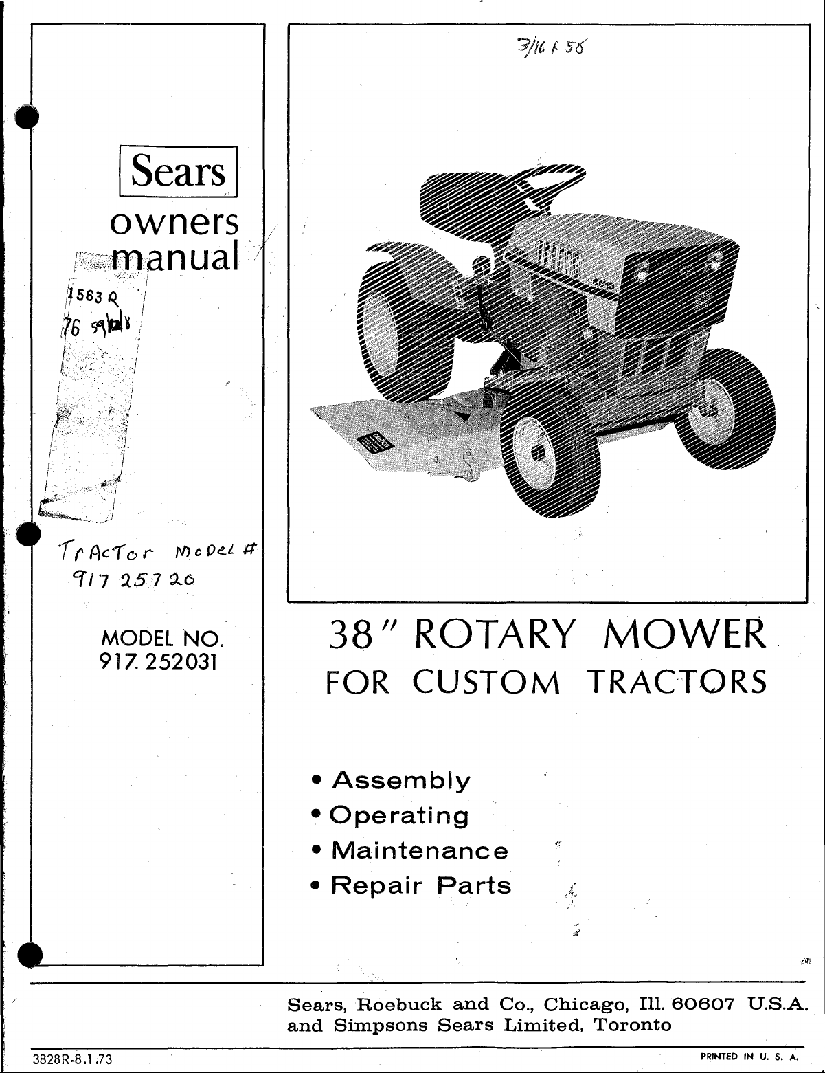
38/1 ROTARY
FOR
•
Assembly
•
Operating
•
Maintenance
•
Repair
CUSTOM TRACTORS
Parts
MOWER
Sears,
and
3828R-8.1.73
Roebuck
Simpsons
and
Sears
Co.,
Chicago,
Limited,
Ill.
Toronto
60607
PRINTED
U.S.A.
IN
u.
S.
A.
During
material
of
our
The
guarantee
the
first
year, we wi II
or workmanship.
stores
or
service
is
limited
repair
This
guarantee
centers
to 30 days
your mower free
service
throughout the
if
the item
is
avai
United
is
used
States or Canada.
IMPORTANT
RULES
FOR
SAFE
OPERATION
of
charge
lable
for
commercial purposes.
by
if
found
simply
defective
contacting
in
any
1. Know
READ
2. Do
mower. Do
out
3.
Do not
pets a safe
4.
Clear
picked
5.
Disengage
before
6.
Disengage
leaving
7.
Do
stacles
mower
removing
hands
when
8.
Disengage
not
9.
Take
tractor
gaging
into
engine
the
controls,
THE
OWNER'S MANUAL.
not
allow
proper
work
up and
attempting
operator
not
attempt
before
,or
engine
in
use.
all
and
power
neutral,
and removing key.
children
not
allow
instructions.
carry
passengers.
di
stance
area
thrown.
mower
power
rosition.
to
or
otherwise
wire
from
feet
in or
is
running.
power
possible
mower
take-off,
setting
to
stopping
and
to
adults
away.
of
objects
clutch,
to
start
mower and
clean
clean,
spark
near
rotating
to
mower when
precautions
unattended:
lowering mower,
parking
how
to
operate
to
operate
Keep
which might
and
shift
engine.
stop
discharge,
adjust
tractor
plug. Never
blades
such
brake,
stop
quickly
Tractor
them with-
children
into
neutral
engine
transporting
when
remove
or
engine,
or
leaving
as
shifting
stopping
before
repair
place
belts
disen-
and
and
be
ob-
and
or
-
'14. Watch
roadways.
15. When
terial
Never
tion.
16.
Handle
able.
A.
Use
B.
Never
ning
doors.
C.
Open
exhaust
eng i ne ind
D.
Never
17.
Keep
dition
18.
Keep
sure
19.
Never
a
building
flame
20.
Allow
closure.
21.
To
reduce
leaves
out
for
using
mower
towards
allow
anyone
gasoline
approved
remove
or
hot
Wipe up
doors
fumes
smoke
tractor
all
equipment
store
or
engine
and
nuts,
spark.
fire
or
excessive
and
keep
tractor
where
traffic
never
bystanders,
near
with
care--it
gasoline
cap
spilled
if
are
while
mower
safety
bolts,
is
in
with
fumes
cool
or
engine
before
keep
grease.
engine.
oors.
to
hazard
when
crossing
direct
windows
vehicle
container.
add
gasoline
Never
fill fuel
gasoline.
is
dangerous.
refueling
in
good
devices
and
screws
safe
working
gasoline
may
storing
engine
discharge
or
while
is
highly
to
tcnk
run in
Do
engine.
operat i ng
in
place.
tight
condition.
in
tank
reach
in
free
or
near
of
ma-
buildings.
in
opera-
flamm-
a run-
in-
garage--
not
run
con-
to
be
inside
an
open
any
en-
of
grass,
10. Do not
hill or
of
11.
Reduce
prevent
extreme
slopes.
12.
Stay
hazards.
13.
Use
equi pment:
A.
B.
C.
D.
3828R-8.1.73
steep
alert
care
Use
Limit
Do
not
Use
when
stop
or
downhill.
slopes,
speed
on
tipping
caution
for
holes
when pulling
only
approved
loads
to
turn
sharply.
counter
suggested
start
Drive
never
slopes
or
loss
when
In
those
weight
in
suddenly
up and down
across
and
in
of
control.
changing
terrain
loads
drawbar
you
can
Use
core
(S)
or wheel
owners
and
when
the
sharp
or
hitch
safely
when
manual.
going
the
face.
turns
Exercise
direction
other
hidden
using
heavy
points.
control.
backing.
weights
up-
face
on
to
22.
23.
24. When
- 1 -
Tractor
inspected
obj
ect
restarting
Do
overspeed
1.
2.
3.
4.
and
not
using
Mow
light.
Never
running.
Shut
Check
bolts,
frequent
and Mower
for
damage
damage
and
operating
change
only
make
engine
eng i
tractor
,
blade
nuts
interval
engine
ne.
in
daylight
any
off
mounting
etc.
should
after
shou
Id
be
the
governor
with
mower:
or
adjustment
when
bolts
for proper
s.
be
stopped
striking a foreign
repaired
equipment.
settings
in
good
while
engine
unclogging
and all
tightness
and
before
or
artificial
is
chute.
other
at
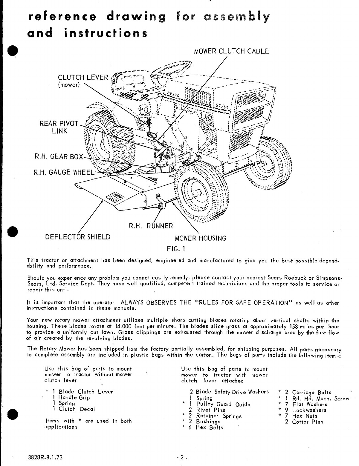
reference
drawing
for
assembly
and
REAR
R.H.
instructions
CLUTCH
{mower}
PIVOT
LINK
GEAR
LEVER
BOX
MOWER
CLUTCH
CABLE
DEFLECTOR
Thi s
tractor
abi I ity and
Should
Sears,
repair
It
instructions
Your new
housing.
to
of
The
to
you
Ltd.
this
is
important
These
provide
air
created
Rotary
complete
Use
mower to
clutch
* 1
Items
applications
or
attachment
performance.
experience
Service
unti.
that
contained
rotary
mower
blades
a uniformly
by
Mower
assembly
this
bag
tractor
lever
Blade
1
Handle
1 Spring
1
Clutch
with * are
Dept.
the
the
has
of
Clutch
Grip
Decal
SHIELD
has
any
yroblem
They
operator
in
these
attachment
rotate
!=ut
lawn.
revolving
been
shipped
are
included
parts
without
Lever
used
been
have
manuals.
at
14,000
Grass
blades.
to
mount
mower
in
R.H.
designed,
you
cannot
well
ALWAYS
utilizes
feet
clippings
from
in
plastic
both
engineered
~?S
qualified,
OBSERVES
multiple
per
minute.
the
factory
bags
MOWER
FIG.
i
Iy
remedy,
competent
sharp
are
exhausted
partially
within
1
and
plea~e
THE
cutting
The
blades
the
Use
this
mower
clutch
2
1
* 1
2
2
*
* 2
* 6
HOUSING
manufactured
contact
trained
"RULES
assembled,
carton.
Blade
Spring
Pulley
Rivet
Retainer
Bush
Hex
blades
slice
through
The
bag
to
tractor
lever
Safety
Guard
Pins
ings
Bolts
technicians
of
to
'y?ur
FOR
SAFE
rotating
grass
the
mower
for
shipping
bags
parts
with mower
attached
Drive
Guide
Springs
give
you
nearest
at
of
to
Washers
Sears
and
the
OPERATION"
about
approximately
discharge
purposes.
parts
include
mount
the
best
Roebuck
proper
vertical
area
* 2
* 1
7
*
* 9
* 7
2
possible
or
tools
as
shafts
158
by
All
the
Carriage
Rd. Hd. Mach.
Flat
Lockwashers
Hex
Cotter
Sim.psons-
to
service
well
as
within
miles
per
the
fast
parts
necessary
following
Bolts
Washers
Nuts
Pins
depend-
or
other
the
hour
flow
items:
Screw
3828R-8.1.73
·2-
table
GUARANTEE
of
contents
ASSEMBLY
INSTRUCTIONS
OPERATING
MAINTENANCE
REPAIR
PARTS
assembly
Assembly
this
before
A
letter
refers
unless
L.H.
behind
the
1.
Cut
other
parts,
of
parate
as
well
Owners
to an arrow in an
(Left
tractor
Manual
beginning
in
parentheses
otherwise
Hand)
the
steering
seat
all
wires,
parts
and
mower.
bolts
and
from
hardware
Layout
as
to
stated.
is
wheel
remove mower,
etc.
all
of
should
assemble
in
the
adjoining
When R.H.
used,
it
a s if
facing
carton.
necessary
parts
according
the
different
be
studied
your
following
Figure
means
one
forward.
Plastic
for
assembly,
to
Rotary
(i
(Right
from a
were
plastic
bag
for
the
size.
3-6
7-8
8-9
10-14
sections
very
closely
Mower.
instructions
Ilustration),
Hand) or
position
seated
bags,
contains
assembly
and
of
on
and
se-
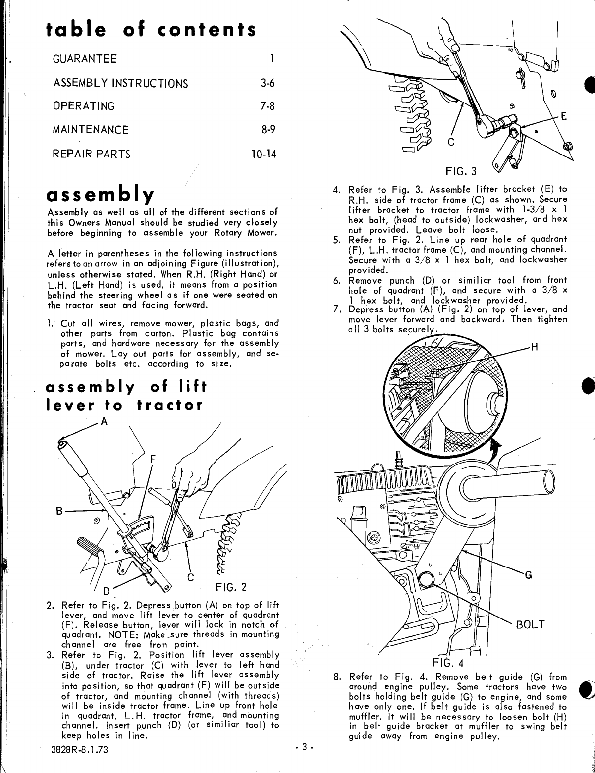
4.
Refer
R.H.
I
ifter
hex
nut
5.
Refer
(F),
Secure
provided.
6.
Remove
hole
1
7.
Depress
move
all 3 bolts
to
side
bracket
bolt,
provided.
to
L.H.
with a
of
hex
bolt,
lever
Fig.
3.
of
tractor
to
(head
Leave
Fig.
2.
tractor
3/8
punch
quadrant
and lock
button
forward
ses;urely.
FIG.3
Assemble
frame (C)
tractor
to
outside)
line
frame (C), and mounting
x 1
(D)
or s im
(F),
(A)
(Fig.
and
.~--~
lifter
bracket
as
shown.
frame
bolt
up
hex
and
washer
2) on
backward.
with
lockwasher,
loose.
rear
hole
bolt,
and
iii ar tool from front
secure
with a 3/8
provided.
top
of
Then
(E)
Secure
1-3/8
x 1
and
hex
of
quadrant
channel.
lockwasher
lever,
and
tighten
to
x
assembly
lever
to
of
lift
tractor
B------""-
FIG.2
2.
Refer
to
Fig.
2.
lever,
(F).
quadrant.
channel
3.
Refer
(B),
side
into
of
will
in
channel.
keep
and move lift
Release
are
to
under
of
tractor.
position,
tractor,
be
inside
quadrant,
Insert
holes
Depress
button,
NOTE:
Fig.
Make
free
2.
tractor
Raise
so
that
and mounting
tractor
L.
H.
punch (D) (or
in
line.
3828R-8.1.73 - 3 -
button
lever
lever
.sure
from
paint.
Position
(C) with
the
quadrant
frame.
tractor
(A)
to
center
will lock in
threads
lift
lever
lever
lift
lever
(F)
will
channel
line
frame, and
similiar
on
top
of
quadrant
notch
in
mounting
assembly
to
left
assembly
be
(With
threads)
up front
mounting
tool)
of
lift
().f
hand
outside
hole
to
8.
Refer
around
bolts
have
only
muffler.
in
belt
guide
to
Fig.
eng
holding
It
guide
away from
4.
ine pu Iley. Some
belt
one.
If
will
be
bracket
FIG.4
Remove
guide
belt
guide
necessary
at
engine
belt
tractors
(G) to
is
to
muffler to
pulley.
guide
engine,
also
loosen
(G)
have
and
fastened
bolt
swing
from
two
some
to
(H)
belt
,
..
'
~
asselT,lbly
assembly
deflector
to
mower
shield
(cont.)
of
housing
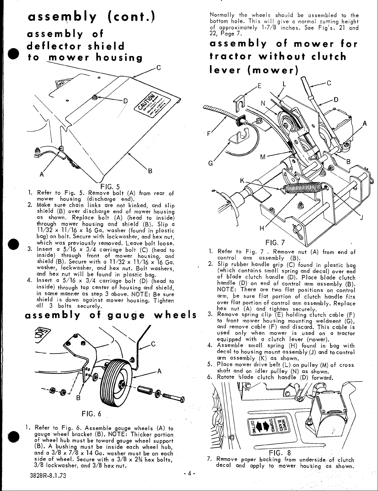
Normally
bottom
of
approximately
22,
Page
the
hole.
7.
wheels
Thi 5
assembly
tractor
should
wi
II
give
1·7/8
inches.
of
without
be
assembled
a normal
See
cutting
Fig's.
mower
clutch
to
height
21
and
for
the
A
1.
Refer
to
mower
2. Make
shield
as
through mower
11/32 x 11/16
bag)
which
3.
Insert a 5/16 x 3/4
inside)
shield
washer,
and
4.
Insert a 5/16 x 3/4
inside)
in
same
shield
all
housing
sure
(B)
shown.
on
bolt.
was
through
(B).
lockwasher,
hex
nut
through
manner
is
3
bolts
Fig.
previously
down
assembly
5.·
chain
over
Replace
x 16
Secure
Secure
will
top
as
securely.
FIG. 5
Remove
(discharge
links
discharge
housing
with
front
with a 11/32 x 11/16 x 16
be
center
step 3 above.
against
of
are
bolt
and
Ga.
washer
lockwasher,
removed.
carriage
of
and
found
carriage
mower
gauge
bolt
not
end
(A)
mower
hex
in
of
(A) from
end).
kinked,
of
mower
(head
shield
(found in
Leave
bolt
nut.
Bolt
plastic
bolt
housing
NOTE:
housing.
(B).
and
bolt
(C)
housing,
bag.
(0)
and
rear
of
and
slip
housing
to
inside)
Slip
plastic
hex
nut,
loose.
(head
to
and
Ga.
washers,
(head
to
shield,
Be
sure
Tighten
wheels
lever
a
(mower)
FIG. 7
1.
Refer
to
Fig.
7 .
control
2.
Slip
rubber
(which
of
blade
handle
NOTE:
arm, ,be
over
flat
hex
3.
4.
5.
6.
nut
Remove
to front mower
remove
and
u~ed
on
equipped
Assemble
decal
to
arm
assembly
Place
mower
shaft
and
Rotate
arm
handle
contains
clutch
(0)
on
There
sure
portion
(A) and
spring
cable
Iy
wh
with a
small
housing
drive
on
"'lade
Remove
assembly
grip
small
handle
end
of
are
two
flat
portion
of
control
tighten
clip
(E)
housing
(F)
en mower
clutch
spring
mount
(K)
as
belt
idler
pulley
clutch
handle
nut
(B).
(C) found in
spring
and
(0).
Place
control
flat
positions
of
arm
securely.
holding
mounting
and
discard.
is u sed
lever
(H) found
assembly
shown.
(L) on
(N)
pulley
as
(0)
(A) from
plastic
decal)
blade
arm
assembly
clutch
assembly.
handle
clutch
weldment
This
on a
(rlower).
in
(J)
and
(M)
shown.
forward.
over
on
Replace
cable
cable
bag
to
of
end
of
bag
end
clutch
(B).
control
fits
(F)
(G),
is
tractor
with
control
cross
FIG.6
1.
Refer
to
Fig.
6.
gauge
of
(B). A bushin9
and a 3/8 x 7/8 x 14
side
3/8
3828
wheel
wheel
hub
of
wheel.
lockwasher,
R-8.l
.73
bracket
must
must
Secure
and
Assemble
(B).
be
Ga.
3/8
gauge
NOTE:
toward
be
with a 3/8
inside
washer
hex
gauge
nut.
wheels
Thicker
each
must
x 2%
wheel
wheel
be
hex
(A)
portion
support
hub,
on
each
bolts,
to
- 4 -
7.
Remove
decal
paper
and
backing
apply
FIG. 8
from
to mower hous,ing
underside
of
as
clutch
shown.
 Loading...