

Page 1

/ Ro
®
NIODEL MBER 917.251560
oAssembly
®Operation
, Customer Responsibilities
• Service and Adjustments
oRepair Parts
OWNER'S MANUAL
CAUTION: Read and follow all safety rules and instructions before operating this equipment.
FOR CONSUMER ASSISTANCE HOT LINE, CALL THIS TOLL FREE NUMBER: 1_800_659-5917
Page 2
SAFETY RULES
Safe Operation Practices for Ride-On Mowers i_
IMPORTANT: THIS CUTTING MACHINE IS CAPABLE OF AMPUTATING HANDS AND FEETAND THROWING OBJECTS..
FAILURE TO OBSERVE THE FOLLOWING SAFETY INSTRUCTIONS COULD RESULT IN SERIOUS INJURY OR DEATH_
I. GENERAL OPERATION
• Read, understand, and follow all instructionsin the manual_:=
and on the machine before starting_
° Only allow responsible adults, who are familiar with the
instructions, to operate the machine.
• Clear the area of objects such as. rocks, toys, wire, etc.,
which could be picked up and thrownby the blade,
° Be surethe area isclear ofotherpeople before mowing. Stop
machine ifanyone enters the area,
• Never carry passengers.
• Donotmow in reverse unless absolutelynecessary. Always
look down and behind before and while backing°
• Beaware of the mower dischargedirection and do not point
it at anyone. Do not operate the mower without either the
entire grass catcher or the guard in place.,
. Slow down before turning.
• Neverleave a runningmachine unattended. Always turn off
blades, set parking brake, stop engine, and remove keys
before dismounting.
• Turn off blades when not mowing
• Stop engine before removing grass catcher or unclogging
chute.
• Mow only in daylight or good artificial light.
• Do not operate the machine while under the influence of
alcohol or drugs.
• Watch for traffic when operating near or crossing roadways,.
• Use extra care when loading or unloading the machine into
a trailer or truck.
U. SLOPE OPERATION
Slopes are a major factor related to loss-of-control and
tipover accidents, which can result in severe injury ordeatho
All slopes require extra caution. If you cannot back up the
slope or if you feet uneasy on it, do not mow it.
DO,
• Mow up and down slopes, not across_
• Remove obstacles such as rocks, tree limbs, etco
• Watch for holes, ruts, or bumps. Uneven terrain could
overturn the machine. Taft grass can hide obstacles_
° Use slow speed_ Choose a low gear so that you will not have
to stop or shift while on the slope..
• Follow the manufacturer's recommendations for wheel
weights or'counterweights to improve stability.
• Use extra care with grass catchers or other attachments°
These can change the stability of the machine.
* Keep all movement on the slopes slow and gradual Do not
make sudden changes in speed or direction.
- Avoid starting or stopping on a slope. If tires lose traction,
disengage the blades andproceed slowlystraightdownthe
slope_
DO NOT:
. Donottumonslopesunlessnecessary, andthen, turnslowly
and gradually downhill,if possible.
° Do notmow near drep-offs, ditches, or embankments. The
mower could suddenly turn over ifa wheel is over the edge
of a cliffor ditch, or ifan edge caves in,
• Do not mow on wet grass_ Reduced traction could cause
sliding.
• Do not try to stabilize themachine by puttingyour foot onthe
ground.
• Do notuse grass catcher on steep slopes.
III, CHILDREN
Tragic accidents can occur if the operator' is not alert to the
presence of children. Children are often attracted to the
machine and the mowing activity, Never assume that
children will remain where you last saw them°
• Keep children out ofthe mowing area and underthe watchful
care of another responsible adulL
= Be alert and turn machine off if children enter the area.,
= Before and when backing, look behind and down for small
children.
• Never carry children. They may fail off and be seriously
injured or interfere with safe machine operation.
• Never allow children to operate the machine.
° Use extra care when approaching blind corners, shrubs,
trees, or other objects that may obscure vis[ono
IV, SERVICE
• Use extra care in handlinggasoline and otherfuelso Theyare
flammable and vapors are explosive,
Use only an approved container,
Never remove gas cap or add fuel with the engine
running. Allow engine to cool before refueling_ Do not
smoke.
Never refuel the machine indoors.
Never store the machine or fuel container inside where
• Never run a machine inside a closed area_
• Keep nuts and bolts, especially blade attachment bolts, tight
• Never tamper with safety devices. Ch_uk their proper'
• Keep machine free of grass, leaves, or other debris build-up.
° Stop and inspect the equipment if you strike an object,
° Never make adjustments or repairs with the engine running.
° Grass catcher components are subject towear, damage, and
° Mower blades are sharp and can cut. Wrap the blade(s) or
° Check brake operation frequently, Adjust and service as
there is an open flame, such as awater heater'.
and keep equipment in good condition.
operationregularly.
Clean oil or fuel spiElage. Allow machine to cool before
stodng.
Repair, if necessary, before restarting.
deterioration, which could expose moving parts or allow
objects to be thrown. Frequently check components and
replace with manufacturer's recommended parts, when nec-
essary.
wear gloves, and use extra caution when servicing them.
required.
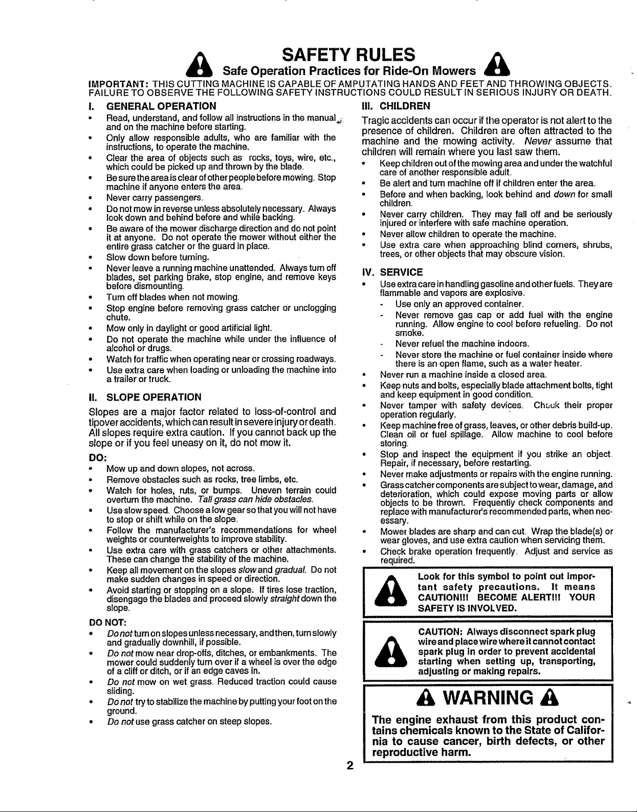
tant safety precautions, it means
Look for this symbol to point out impor-
CAUTIONII! BECOME ALERTlll YOUR
SAFETY IS iNVOLVED.
iiiii1_//1/11/iiiiwlJul .................
CAUTION: Always disconnect spark plug
spark plug in order to prevent accidental
wireand placewire whereit cannot contact
starting when setting up, transporting,
iiiiiiiiiiiii iii
adjusting or making repairs.
A WARNING A
The engine exhaust from this product con-
tains chemicals known to the State of Califor-
nia to cause cancer, birth defects, or other
reproductive harm.
I III III I IIII II
2
Page 3

CONGRATULATIONS on your purchase of a Sears
Tractor. it has been designed, engineered and manufac-
tured to give you the best possible dependability and
performance.,
Should you experience any problem you cannot easily
remedy, please contact your nearest Sears Authorized
Service Center/Department Department. We have com-,_
petent, well-trained technicians and the proper tools to
se_ce or repair this tractor,
Please read and retain this manual. The instructions will
enable you to assemble and maintain your tractor properly,,
Always observe the "SAFETY RULES".
MODEL
NUMBER 917,.251560
SERIAL
NUMBER
DATE OF PURCHASE
THE MODELAND SERIAL NUMBERSWILL BE FOUND
ON A PLATE UNDER THE SEAT°
YOU SHOULD RECORD BOTH SERIAL NUMBERAND
DATE OF PURCHASE AND KEEP IN A SAFE PLACE
FOR FUTURE REFERENCE.
MAINTENANCE AGREEMENT
A Sears Maintenance Agreement isavailable on this prod-
uct. Contact your nearest Sears store for details°
CUSTOMER RESPONSIBILITIES
• Read and observe the safety nJles.
• Foliow a regularschedule in maintaining, caring for and
using your tractor,
° Follow the instructions under"Customer Responsibili-
ties" and "Storage" sections of this owner's mantJal,
PRODUCT SPECiFiCATiONS
HORSEPOWER: 22,5
GASOLINE CAPACITY 3°5 GALLONS
_,NDTYPE: UNLEADED REGULAR
OIL TYPE (API-SF/SG): SAE 10W30 (above 32°F)
SAE 5W-30 (below 32°F)
OIL CAPACITY: W/FILTER: 4°2 PINTS
W/O FILTER: 3,.7 PINTS
SPARK PLUG: CHAMPION RC12YC
(GAP: .030")
VALVE CLEARANCE: NOT ADJUSTABLE
GROUND SPEED (MPH): FORWARD: 0- 5.6
REVERSE: 0- 2°5
TIRE PRESSURE: FRONT: 14 PSi
REAR: 10 PSi
CHARGING SYSTEM: !5 AMPS @ 3600 RPM
BATTERY: AMPtHR: 35
MIN. CCA: 280
CASE SIZE: U1R
BLADE BOLT TORQUE: 30-35 FT.. LBS,.
WARNING: This tractor is equipped with an internal
combustion engine and should not be used on or near any
unimproved forest-covered, brush-covered or grass-cov-
ered land unless the engine's exhaust system is equipped
with aspark arrester meeting applicabIe local or state laws
(if any)° If a spark arrester is used, it should be maintained
in effective working order by the operator.
In the state of California the above is required by law
(Section 4442 of the California Public Resources Code),
Other states may have similar tawso Federal laws apply on
federal lands., A spark arrester for the muffler is available
through y_ournearest Sears Authorized Service Center/
Department (See REPAIR PARTS section ofthis manual),,
LIMITED TWO YEAR WARRANTY ON CRAFTSMAN RIDING EQUIPMENT
For two (2) years from the date of purchase, ifthis Craftsman Riding Equipment is maintained, lubricated and tuned up according
to the instructions in the owner's manual, Sears will repair or replace, free of charge, any parts found to be defective in material
or workmanship
This Warranty does not cover:
• Expendable items which become worn during normal use, such as blades, spark plugs, air cleaners, belts, etc.
• Tire replacement or repair caused by punctures from outside objects, such as nails, thorns, stumps, or glass°
= Repairs necessary because of operator abuse, negligence, improper storage or accident or the failure to maintain the
equipment according to the instructions contained in the owner's manual
° Riding equipment used for commercial or rental purposes_
LIMITED 90 DAY WARRANTY ON BATTERY
For ninety (90) days from date of purchase, if any battery included with this tiding equipment proves defective in material or
workmanship and our testing determines the battery will not hold a charge, Sears willreplace the battery at no charge.
IN-HOME WARRANTY SERVICE ON YOUR CRAFTSMAN RIDING EQUIPMENT IS AVAILABLE AT NO-CHARGE FOR 30
DAYS FROM THE DATE OF PURCHASE,, PLEASE CONTACT YOUR NEAREST SERVICE CENTER. AFTER 30 DAYS
FROM THE DATE OF PURCHASE, WARRANTY SERVICE IS AVAILABLE BY TAKING YOUR CRAFTSMAN RIDING EQUIP-
MENT TO YOUR NEAREST SEARS SERVICE CENTER. (IN-HOME WARRANTY SERVICE WILL STILL BE AVAILABLE
AFTER 30 DAYS FROM THE DATE OF PURCHASE BUT A STANDARD TRIP CHARGE WILL APPLY,) THIS WARRANTY
APPLIES ONLY WHILE THIS PRODUCT iS IN THE UNITED STATES,,
This Warranty gives you specific legal rights, and you may also have other dghts which may vary from state to state,,
SEARS, ROEBUCK AND CO. D/817 WA, HOFFMAN ESTATES, 1L 60179
3
Page 4
TABLE OF CONTENTS
SAFETY RULES ............................................................ 2
PRODUCT SPECIFICATIONS ...................................... 3
CUSTOMER RESPONSIBILITIES ..................... 3, 16-19
WARRANTY .......................................... ,....................... 3 '_
TRACTOR ACCESSORIES ..................................... 5,15
ASSEMBLY ............................................................. 7-10
OPERATION .......................................................... 12-16
INDEX
A
Accessories .............................................................5
Adjustments:
Brake ........................................................23
Carburetor .............................................27
Clutch Pulley ............................................23
Gauge Wheels ................................14
Mower
Front-To-Back ................................22
Side-To-Side .................................21
Throttle Control Cable ........................27
Air Filter',Engine......................................20
Air Screen, Engine ...................................19
Assembly...................................................7'-10
B
Battery:
Charging ..................................................8
Cleaning ............................................20
Starting with Weak Battery ........... 25
Storage ................................................28
Terminals ............................................19
Bell:
Motion Drive
Remoyal/Replacement ...............24
Mower Drive
Removal/Replacement ............ 22
Mower Blade Drive
Removal!Replacement ..................23
Brade:
Sharpening .........................................!8
Rep{acement .......................................18
Brake Adjustment .........................................23
C
Carburetor Adjustment ................................27
Clutch Pulley ............................................23
Controls, Tractor .......................................12
Customer Responsibilities.................17-20
Engine:
Air Filter ...............................................20
Air Screen .................................. 19
Cooling Fins .....................................20
Engine Oil .................................15,19
Fuel Filler ................................... 20
Spark Plug(s) ..................................20
Tractor:
Battery ............................................18
Blade ............................................ 18
LubricationChad .........................17
Maintenance Schedule ............. 17
Tire Care ..............................8,18,25
Transaxle .................................... 19
Cutting Height, Mower ...............................t3
Electrical:
Interlocks and Relays ..........................26
Schematic .................................................31
Widng Diagram ..................................32
Engine:
Air' Filter.................................................20
Air Screen ..................................:......19
Cooling Fins ................................................20
Oil Change .............................................19
Oil Level ..............................................15
Oil Type ........................................15,t9
Preparation ..................................i......... 15
Repair Pads ....................................51-58
Starting ..............................................15-16
Storage ..............................................28
Filter:
Air Filter .................................................20
Fuel ..........................................................20
,Oil .................................................................20
Fuel:
Storage ................................................28
Type ..........................................................15
Fuse .....................................................................26
Headlights ...................................................26
Hood Removal/Installation ......................26
Leveling Mower Deck .............................22
Lubrication:
Chad ....................................................17
Engine.........................................................19
Maintenance Schedule ...........................17
Mower:
Adjustment, Front-to-Back .............22
Adjustment, Side*to.Side ...............21
BIade Replacement .............................18
Blade Sharpening ..............................18
CuttingHeight.................................13
Installation ..............i.............................21
Operation ..............................................t4
Removal .............................................21
Mowing Tips................................................16
Muffler........................................................20
Spark Arrester ................................3,40
Oil:
Cold Weather Conditions ..........15,19
Engine ....................................................19
Storage ........................................................28
i iii i III,IHI Ill Ill I I ,
MAINTENANCE SCHEDULE ..................................... 17
SERVICE AND ADJUSTMENTS ........................... 21-27
STORAGE ................................................................... 28
TROUBLESHOOTING ........................................... 29-30
REPAIR PARTS - TRACTOR ................................ 32-50
REPAIR PARTS - ENGINE .................................... 51-58
PARTS ORDERING/SERVICE ............... BACK COVER
E
Operation.....................................................12-16
Operating Mower ..............................................t4
Options:
Accessodes ...............................................5
Spark Arrester. ......................................3,40
P
Parking Brake ................................................... 13
Pads Bag .........................................................6
Parts,ReplacemenVRepair,...............32-50
Product Specifications ....................................3
R
Repair Parts .............................................. 32-50
F
Safety Rules .....................................................2
Seat .................................................................... 8
Service and Adjustments ....................21-27
Carburetor ..............................................27
Clutch Pulley ..........................................23
Fuse ................................................26
Hood Removal/Installation ..............26
Motion Ddve Belt
Removal/Replacement ..............22
H
L
M
Mower Ddve Belt
Removal/Replacement ................22
Mower Blade Drive Belt
Removal/Replacement ...............23
Mower Adjustment
Front-to-Back ..............................22
Side-to-Side .................................21
Mower Removal/installation ......... 21
Tire Care ..........................................8,16,25
Slope Guide Sheet ......................................... 59
Spark Plug(s) ....................................................20
Specifications .....................................................3
Starting the Engine .............................15-16
Steedng Wheel ..........................................7,24
Stoppingthe Tractor....................................13
Storage ..........................................................28
S
T
Throttle Control Cable Adjustment ........27
Tires ...........................................................8,18,25
Troubleshooting Chart .................... 29-30
Transaxle .........................................................19
W
O
Warranty ............................................................................3
Wiring Diagram ...........................................32
Widng Schematic ..........................................31
4
l llll ,,,,,
Page 5
ACCESSORmES A D ATTACHMENTS
These accessories and attachments were available through most Sears retailoutlets and service centers whenthe tractor was purchased°
Most Sears stores can order these items for you when you provide the model number of your tractor,.
ENGINE MAINTENANCE
SPARK PLUG AIRFILTER BLADES BEt.TSGAS CAN ENGINEOIL FUELSTABILIZER
PERFORMANCE
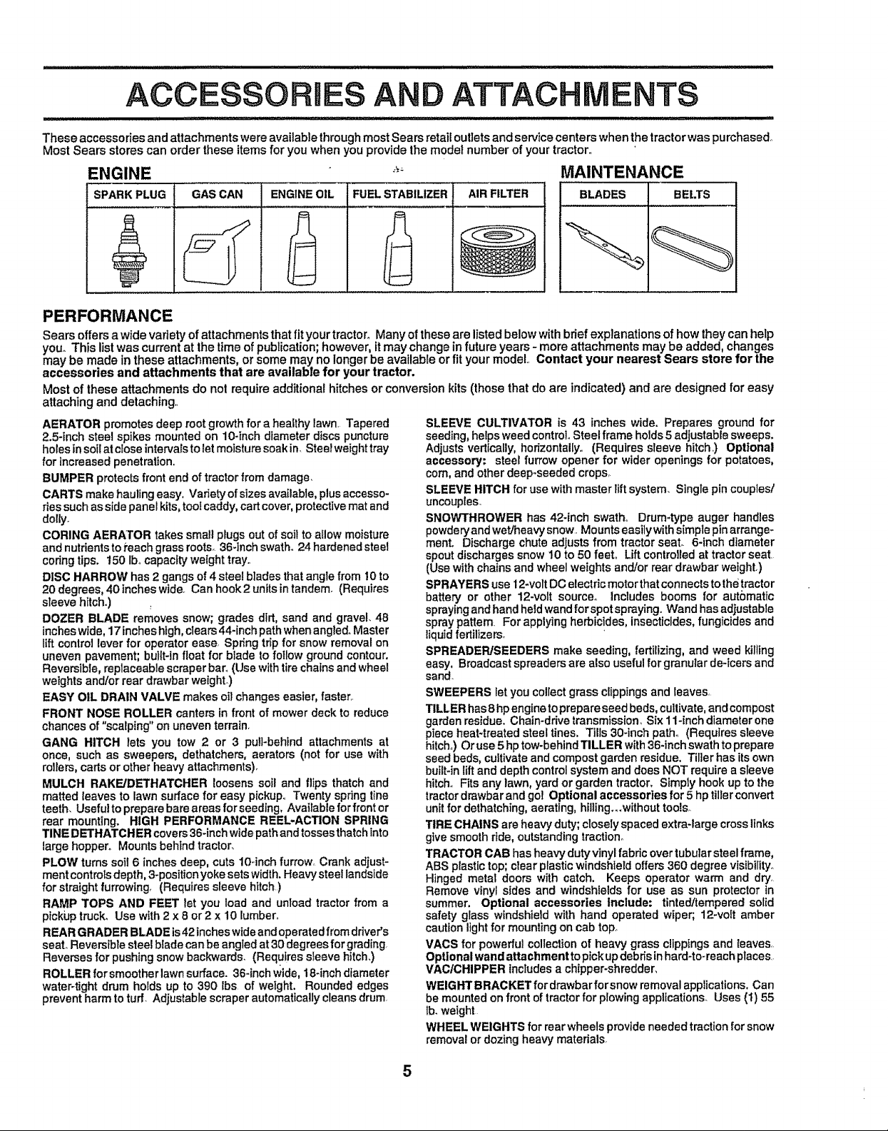
Sears offers a wide variety of attachmentsthatfityour tractor_Many of these are listed below withbrief explanations of how they canhelp
you° This listwas currentat the timeof publication;however, itmay change infuture years - moreattachments may be added, changes
may be made in these attachments, or some may no longerbe available or fit your model., Contact your nearest Sears store for the
accessories and attachments that are available for your tractor,
Most of these attachments do not require additional hitches or conversionkits (those that do are indicated) and are designed for easy
attaching and detaching.,
AERATOR promotesdeep root growth for a healthy lawn, Tapered
2,5-inch steel spikesmountedon 10qnch diameter discs puncture
holesin soilat c!oseintervalstoletmoisture soakin, Stealweighttray
for increasedpenetration,,
BUMPER protectsfront end of tractorfrom damage,
CARTS makehauling easy. Vadetyofsizes available,plusaccesso-
riessuchassidepanelkits,tootcaddy,cartcover,protectivemat and
dolly_
CORING AERATOR takes smallplugs out of soil to allow moisture
and nutrientsto_'eachgrassroots_36-inchswath°24 hardenedsteel
coringtips, 150 Ib, capacityweighttray.
DISC HARROW has2 gangs of 4 steelbladesthat anglefrom 10to
20 degrees, 40 inches wide, Can hook2 units intandem (Requires
sleeve hitch.)
DOZER BLADE removes snow; grades dirt, sand and gravel. 48
incheswide, 17 incheshigh,clears44-inch path when angled. Master
lift control leverfor operator ease, Spring trip for snow removal on
uneven pavement; built-in float for blade to foilow ground contour.
Reversible, replaceable scraperbar°(Usewith tire chains and wheel
weights and/orrear drawbar weight)
EASY OIL DRAIN VALVE makes oil changes easier, faster..
FRONT NOSE ROLLER canters In front of mower deck to reduce
chances of "scalping" on uneven terratn,
GANG HITCH lets you tow 2 or 3 pu!i-behind attachments at
once, such as sweepers, dethatchers, aerators (not for use with
rollers, carts or other heavy attachments)_
MULCH RAKE/DETHATCHER loosenssoil and flips thatch and
matted leaves to lawn surface for easy pickup, Twenty spring line
teeth. Useful toprepare bare areas forseeding, Available forfront or
rear mounting. HIGH PERFORMANCE REEL-ACTION SPRING
TINE DE'THATCHERcovers36-inchwide path andtossesthatch into
large hopper° Mounts behind tractor_
PLOW turns soil6 inchesdeep, cuts 10-inch furrow_Crank adjust-
ment controls depth, 3-position yoke sets width. Heavy steel landstde
for straight furrowing, (Requires sleeve hitch)
RAMP TOPS AND FEET tot you load and unload tractor from a
pickup truck. Use with2x 8 or2 x 10 lumber°
REARGRADER BLADE is42incheswideand operated from driver's
seat°Reversible steel blade can be angled at 30degrees forgrading
Reverses for pushing snow backwards. (Requ!res sfeeve hitch.)
ROLLER forsmootherlawn surface. 36-1nchwide, 18-inch dtameter
water-tight drum holds up to 390 Ibs of weight, Rounded edges
prevent harm to turf. Adjustable scraper automatically cleans drum
SLEEVE CULTIVATOR is 43 inches wide. Prepares ground for
seeding, helpsweedcontrol,Steel frame holds 5 adjustable sweeps.
Adjustsvertically,hofizontallyo(Requires sleeve hitch,) Optional
accessory: steelfurrowopener for wider openings for potatoes,
corn,and otherdeep-seededcrops,
SLEEVE HITCH for usewith masterliftsystem, Singlepincouples/
uncouples,
SNOWTHROWER has 42-inch swath° Drum-type auger handles
powderyandwet/heavysnow Mountseasilywithsimplepinarrange-
ment. Dischargechuteadjustsfrom tractor seat, 6-inch diameter
spoutdischargessnow10 to 50 feet. Liftcontrolledat tractorseat
(Use withchainsand wheelweightsand/orrear drawbar weight)
SPRAYERS use 12-voltDCelectricmotorthatconnectstothetractor
battery or other 12-volt source° Includes booms for automatic
spraying andhandheldwandforspotspraying, Wand hasadjustable
spraypattern Forapplyingherbicides, insecticides,fungicides and
liquid fertilizers,
SPREADER/SEEDERS make seeding, fertilizing, and weed killing
easy. Broadcast spreaders are also usefulfor granularde-icersand
sand_
SWEEPERS let you collectgrass clippingsand leaves,
TILLER has 8 hpenginetoprepareseed beds,cultivate,andcompost
garden residue.Chain-drivetransmission, Six1l-inch diameterone
pieceheat-treated steeltines. Tills30-inchpath_ (Requiressleeve
hitch,)Oruse5 hp tow-behindTILLER with36-inchswathtoprepare
seedbeds,cultivateand compostgarden residue. Tillerhasits own
builbinlift and depthcontrolsystemand does NOT require a sleeve
hitch.,Fitsany lawn, yard or gardentractor, Simplyhook up to the
tractordrawbarandgo! Optional accessories for 5 hp tillerconvert
unitfor dethatching,aerating,hilling,,,withouttools_
TIRE CHAINS are heavyduty;closeiyspacedextra-largecrosslinks
givesmooth ride,outstanding traction°
TRACTOR CAB hasheavydutyvinylfabric overtubular steel frame,
ABS plastictop;clear plasticwindshieldoffers360 degreevisibi[ity_
Hinged metal doors with catch. Keeps operator warm and dry,
Remove vinyl sides and windshieldsfor use as sun protectorin
summer. Optional accessories Include: tinted/tempered solid
safety glass windshield with hand operated wiper;.12-voff amber
cautionlight for mountingon cab top_
VACS for powerfulcollectionof heavy grass clippingsand leaves
Optionalwand attachment topickupdebrisinhard-to,reachplaces
VAC/CHIPPER includesachipper*shredder,
WEIGHTBRACKET for drawbarforsnow removalapplications.Can
be mountedonfront oftractorfor plowingapplications_Uses (t) 55
tb.weight
WHEEL WEIGHTS for rear wheels provideneededtraction for snow
removal or dozing heavy materials,
Page 6
............................................... , ,,,,,,,,
i i I IHI I"L I" II IIII IIIII "1""11 IlllJllll
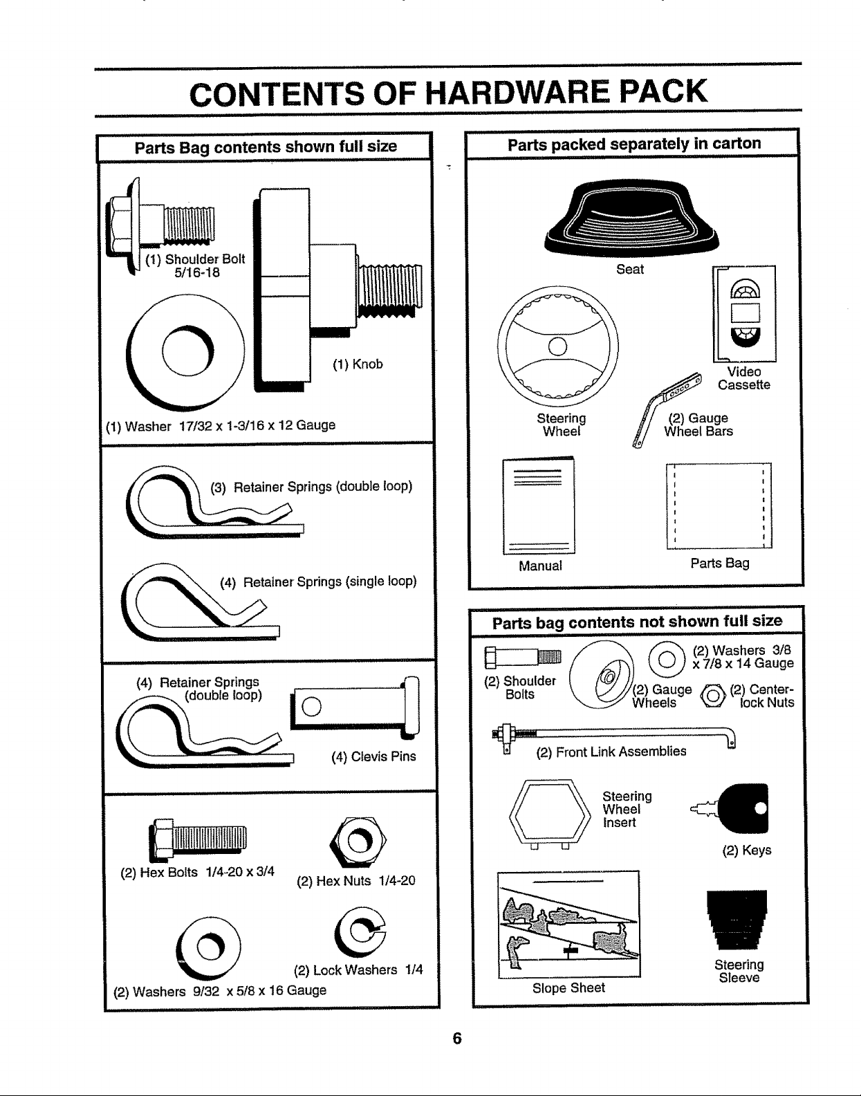
Parts Bag contents shown full size
....................... i iitt IIII]l)ltt]l I '1 I I' ,t ttt
............................ ,,,,,,,,,,
OF HARDWARE PACK
....... , ,,,,,,, iu i Lil,,i , i,,, ........................
Parts packed separately in carton
..................... ,, ,,, ,,
(1) Shoulder Bolt
5/16-18
(1) Knob
(1) Washer 17/32 x 1-3/16 x 12 Gauge
.............. ,,,,,,,,,,,,,,, I iiiiiiiii
II II I]1]1 IIII III
_,__er Sp rings (single loop)
i,iiii, iij, i i i i i lllllllllll,i ii ii
(4) Retainer Springs ........... ,('_1
"_-q,.2JJ ...... :_ (4) Clevis Pins
J
Seat
_a Video
Cassette
Steering
Wheel
Manual
............... i II II I , ii IIIIIIULUII
uge
Bars
Parts Bag
Parts bag contents not shown full size
x 718 x 14 Gauge
(2) Shoulder
Bolts 2) Gauge _ (2) Center-
_12) Front LinkAssemblies
Wheels _ lock Nuts
(2) Hex Bolts 1/4-20 x 3/4
(2) Hex Nuts 1/4-20
(2) Lock Washers 1/4
(2) Washers 9/32 x 5/8 x 16 Gauge
Wheel
Insert
Steering
(2) Keys
Steering
Sleeve
Slope Sheet
............ i,,,,, lllll
6
Page 7
EMBLY
i .......... •.......................
Your newtractor has been assembled atthe factory with the exception ofthose parts left unassembled for shipping purposes,..
To ensure safe and proper operation of your tractor all parts and hardware you assemble must be tightened securely,, Use
the correct tools as necessary to insure proper tightness° _
TOOLS REQUIRED FOR ASSEMBLY
A socket wrench set will make assembly easier. Standard
wrench sizes are listed,
(2) 7/16" wrenches Tire pressure gauge
(1) 1/2" wrench Utility knife
(1) 9/16" wrench
(t) 3/4" socket with drive ratchet
When right or left hand is mentioned in this manual, it
means when you are in the operating position (seated
behind the steering wheel).
TO REMOVE TRACTO RFROM CARTON
UNPACK CARTON
• Remove all accessible loose parts and parts cartons
from carton (See page 6),.
° Cut, fromtop to bottom, along linesonall four corners
of carton, and lay panels flat,.
° Check for any additional loose parts or cartons and
remove.
STEERING
STEERING
BEFORE ROLLING TRACTOR OFF SKID
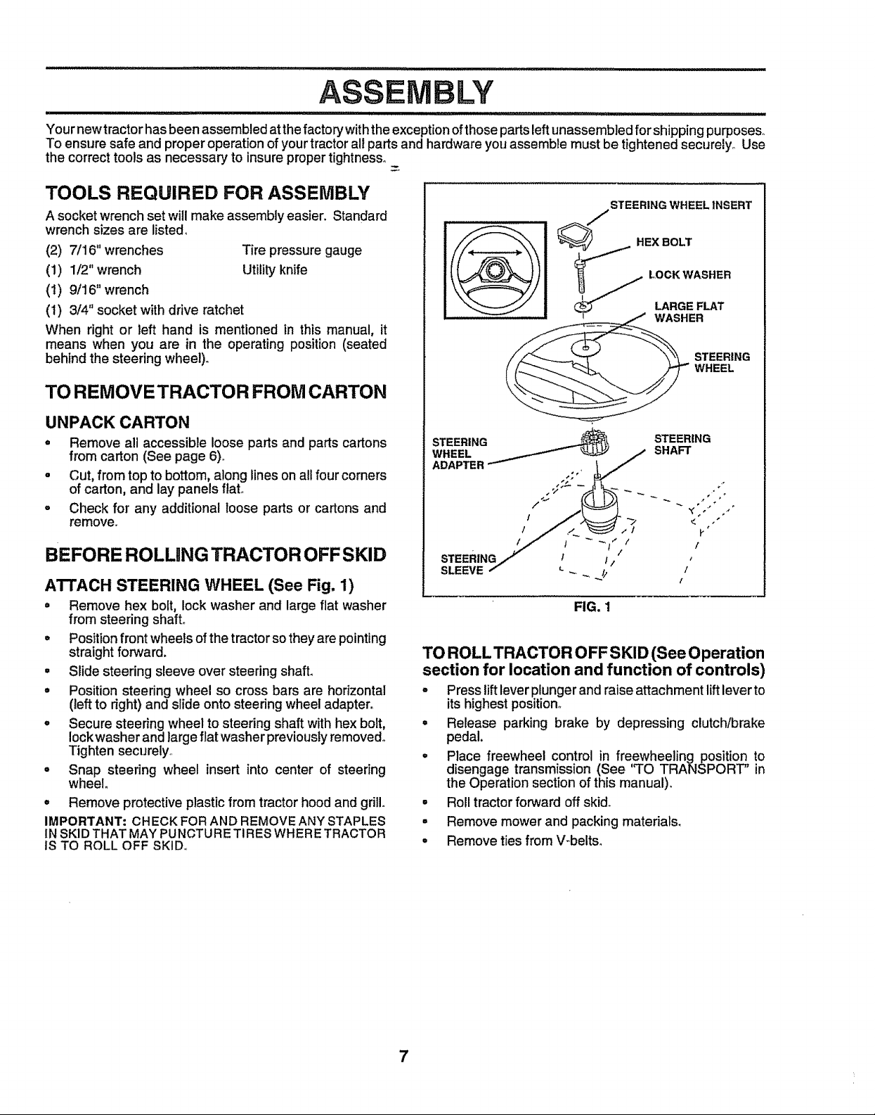
ATTACH STEERING WHEEL (See Fig. 1)
• Remove hex bolt, lock washer and large fiat washer
from steering shaft.
° Position front wheels of the tractor so they are pointing
straight forward.
° Slide steering sleeve over steering shaft.
• Position steering wheel so cross bars are horizontal
(left to right) and slide onto steering wheel adapter.
° Secure steering wheel to steering shaft with hex bolt,
lock washer and large flatwasher previously removed°
Tighten securely,
° Snap steering wheel insert into center of steering
wheel.
° Remove protective plastic from tractor hood and grill.
IMPORTANT: CHECK FOR AND REMOVE ANY STAPLES
IN SKID THAT MAYPUNCTURE TIRES WHERETRACTOR
IS TO ROLL OFF SKID,,
l
FIG. 1
TO ROLL TRACTOR OFF SKID (See Operation
section for location and function of controls)
° Press lift lever plunger and raise attachment lift lever to
its highest position°
° Release parking brake by depressing clutch/brake
pedal.
° Place freewheel control in freewheeling position to
disengage transmission (See '_TOTRANSPORT" in
the Operation section of this manual).
° Roll tractor forward off skid°
= Remove mower and packing materials.
° Remove ties from V-belts_
7
Page 8
.... . ii iii ii iiiiiiiilU i1,111 i i/ IIIIIIIHIIIIIt
LY
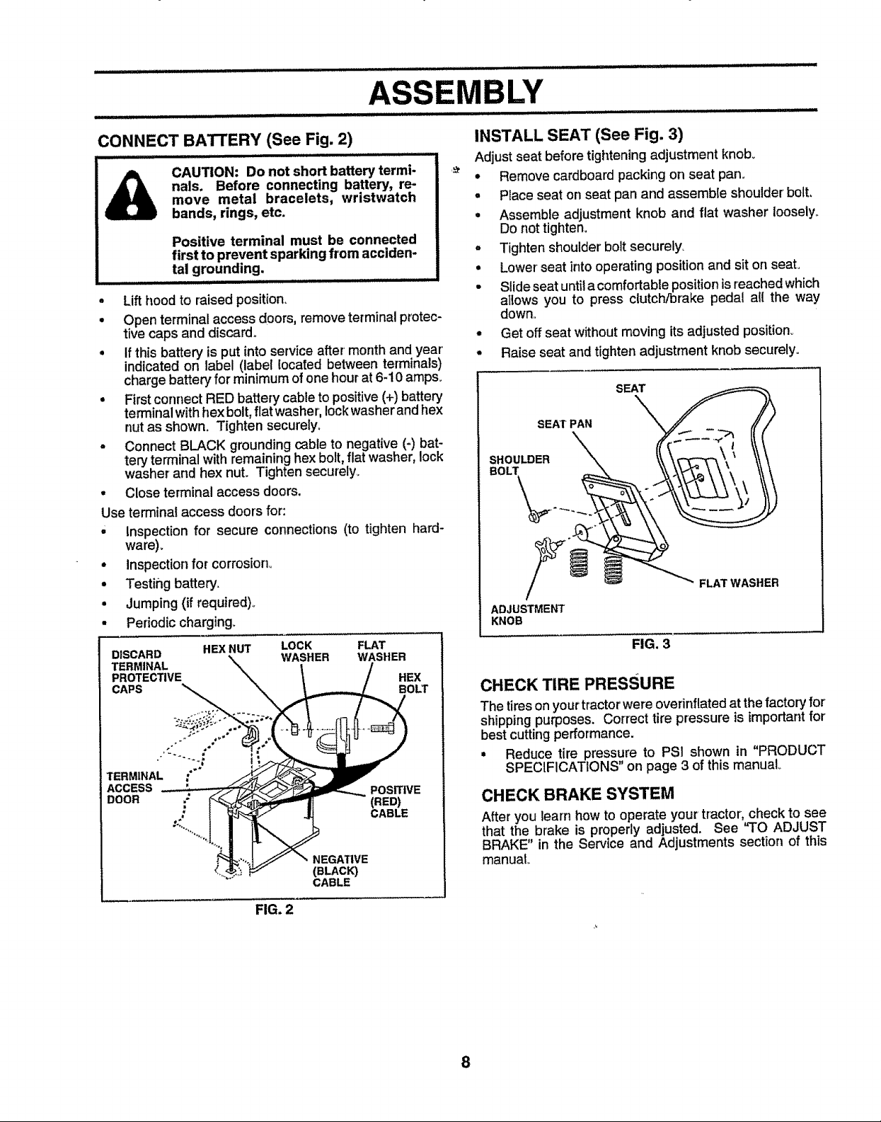
CONNECT BATTERY (See Fig. 2)
CAUTION: Do not short battery termi-
nals. Before connecting battery, re-
move metal bracelets, wristwatch
bands, rings, etc.
Positive terminal must be connected
first to prevent sparking from acciden-
tal grounding.
i, iiii
• Lift hood to raised position.
• Open terminal access doors, remove terminal protec-
tive caps and discard.
• If this battery is put into service after month and year
indicated on label (label located between terminals)
charge battery"for minimum of one hour at 6-10 ampso
• First connect RED battery cable to positive (+) battery
terminal with hex bolt, flat washer, lock washer and hex
nut as shown. Tighten securely.
• Connect BLACK grounding cable to negative (-) bat-
ten] terminal with remaining hex bolt, flat washer, lock
washer and hex nut. Tighten secutelyo
• Close terminal access doors.
Use terminal access doors for:
' inspection for secure connections (to tighten hard-
ware).
• Inspection for corrosion°
• Testing battery.
• Jumping (if required)°
• Periodic charging.
INSTALL SEAT (See Fig. 3)
Adjust seat before tightening adjustment knob_
• Remove cardboard packing on seat pan.
• Place seat on seat pan and assemble shoulder' bolt,
• Assemble adjustment knob and fiat washer loosely,
Do not tighten.
• Tighten shoulder bolt securely.
• Lower seat into operating position and sit on seat.
• Slide seat untila comfortable position is reached which
atlows you to press clutch/brake pedal all the way
down,
• Get offseat without moving its adjusted position°
• Raise seat and tighten adjustment knob securely.
SEAT_\
SEAT PAN _
.O LOER o I
__ _ FLAT WASHER
ADJUSTMENT
KNOB
DISCARD HEX NUT LOCK FLAT
TERMINAL WASHER WASHER
PROTECTIVE
CAPS
TERMINA "" '
ACCESS L_ POStT,VE
DOOR / _ (RED)
,. CABLE
NEGA'f|VE
(BLACK)
CABLE
HEX
BOLT
FIG. 2
FIG. 3
CHECKTIREPRESSURE
The tires onyour tractor were overinflatedat the factory for'
shipping purposes. Correct tire pressure is importantfor
best cutting performance.
• Reduce tire pressure to PS! shown in "PRODUCT
SPECIFICATIONS" on page 3 of this manual°
CHECK BRAKE SYSTEM
After you learn how to operate your tractor, check to see
that the brake is properly adjusted. See "TO ADJUST
BRAKE" in the Service and Adjustments section of this
manual
8
Page 9
ASSEM LY
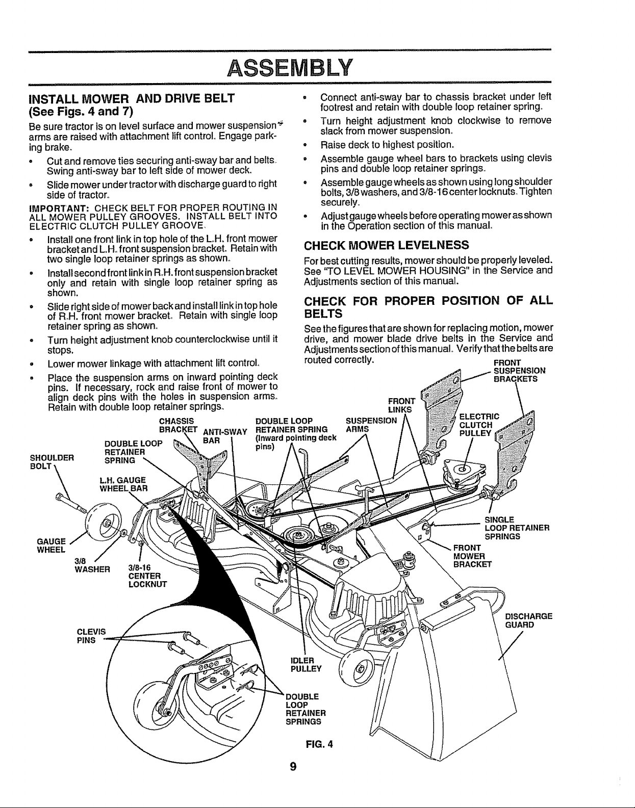
INSTALL MOWER AND DRIVE BELT
(See Figs. 4 and 7)
Be sure tractor is on level surface and mower suspension_ =
arms are raised with attachment lift control Engage park_
ing brake, °
° Cut and remove ties securing anti-sway bar and belts, •
Swing anti-sway bar to left side of mower deck_
o Slide mower undertractor withdischarge guard to right =
side of tractor,
IMPORTANT; CHECK BELT FOR PROPER ROUTING IN
ALL MOWER PULLEY GROOVES. INSTALL BELT INTO °
ELECTRIC CLUTCH PULLEY GROOVE
° Install one front link in top hole of the LH, front mower
bracket and L.H.,front suspensionbracket° Retain with
two single loop retainer springs as shown°
° Installsecond front linkin Roll,front suspension bracket
only and retain with single loop retainer spring as
shown.
° Slide rightside of mower back and install linkin top hole
of R,H, front mower bracket, Retain with single loop
retainer spring as shown°
• Turn height adjustment knob counterclocl_wise until it
stops.
° Lower mower linkage with attachment lift control°
° Place the suspension arms on inward pointing deck
pins. If necessary, rock and raise front of mower to
align deck pins with the holes in suspension arms,
Retain with double loop retainer springs°
CHASSIS DOUBLE LOOP
BRAC ANTI-SWAY RETAINER SPRING
DOUBLE LOOP (Inward pointing deck
RETAINER pins)
SHOULDER SPRING
..... IHI,
Connect anti-sway bar to chassis bracket under left
footrest and retain with double loop retainer spring°
Turn height adjustment knob clockwise to remove
slack from mower suspension°
Raise deck to highest position°
Assemble gauge wheel bars to brackets using clevis
pins and double loop retainer springs.,
Assemble gauge wheels as shown using long shoulder
bolts, 3/8washers, and 3/8-16 center locknutsoTighten
securely.,
Adjust gaugewheels before operating mowerasshown
in the Operation section of this manual°
CHECK MOWER LEVELNESS
Forbest cutting results, mower should be properly leveled.
See "TO LEVEL MOWER HOUSING" in the Service and
Adjustments section of this manual.
CHECK FOR PROPER POSITION OF ALL
BELTS
See the figures thatareshown for replacingmotion, mower
drive, and mower blade drive belts in the Service and
Adjustments section ofthis manual Verify that the belts are
routed correctly. FRONT
SUSPENSION
FRONT
SUSPENSION ELECTRIC
ARMS PULLEY
LINKS
CLUTCH
GAUGE
WHEEL
L.H. GAUGE
WHEEL BAR
3_
WASHER
CLEVIS
PINS
-\
3/8-16
CENTER
LOCKNUT
SINGLE
LOOP RETAINER
SPRINGS
MOWER
BRACKET
DISCHARGE
GUARD
IDLER
PULLEY
LOOP
RETAINER
SPRINGS
FIG, 4
9
Page 10
ASSEMBLY
...................................... t t t Itt tt ItIt It tttt tilt tt ttIt lit tit tttltlttttl
,/CHECKLIST
BEFORE YOU OPERATE AND ENJOY YOUR NEW
TRACTOR, WE WISH TOASSURE THAT YOU RECEIVE
THE BEST PERFORMANCEAND SATISFACTION FROM
THIS QUALITY PRODUCT_
PLEASE REVIEW THE FOLLOWING CHECKLIST:
,/ All assembly instructionshave been completed°
#" No remaining loose parts in carton.
,/ Battery is properly prepared and charged. (Minimum
1 hour at 6 amps).
,/ Seat is adjusted comfortably and tightened securely.
#" All tires are properly inflated. (For shipping purposes,
the tires were ovennflated at the factory)°
,/ Be sure mower'deck is propedyleveled side-to-side!
front-to-rear for best cutting results_ (Tires must be
properly inflatedfor' leveling).
,/ Check mower and drivebelts. Be surethey are routed
propertyaround pulleys and insideall belt keepers°
,/ Check wiring° See that all connectionsare still secure
and wires are properly clamped.
,,/ Before drivingtractor, be sure freewheel controlis in
drive position.
WHILE LEARNING HOW TO USE YOUR TRACTOR, PAY
EXTRA ATTENTION TO THE FOLLOWING IMPORTANT
ITEMS:
#" Engineoil is at proper level.
,/ Fuel tank is filled with fresh, clean, regular' unleaded
gasoline.
,/ Become familiar' with all controls - their location and
function. Operate them before you start the engine.
,/ Be sure brake system is in safe operating condition_
•/ it is importantto purgethe transmission before operat-
ingyour tractorfor'the first time_ Follow proper starting
and transmission purging instructions (See,_O START
ENGINE" and "PURGE TRANSMISSION in the Op-
eration section of this manual).
........................ illllll i i Htll i
10
Page 11
: : : IIIIIIIIIIIIIIIIIIIIIIIIIIIIIIIIIIIIIIIII_ iiiiiiiii I ii_ii_ii _ ii IIIIIIIIIIIIIIIIIIII_I_II_I_I_I_I_I_IILLII i .................... ii
OPERATION
J I i,,,]11111111_1_1i_ _i i i ,,,i,,,H IIII IlL' I'_1111' _.................................
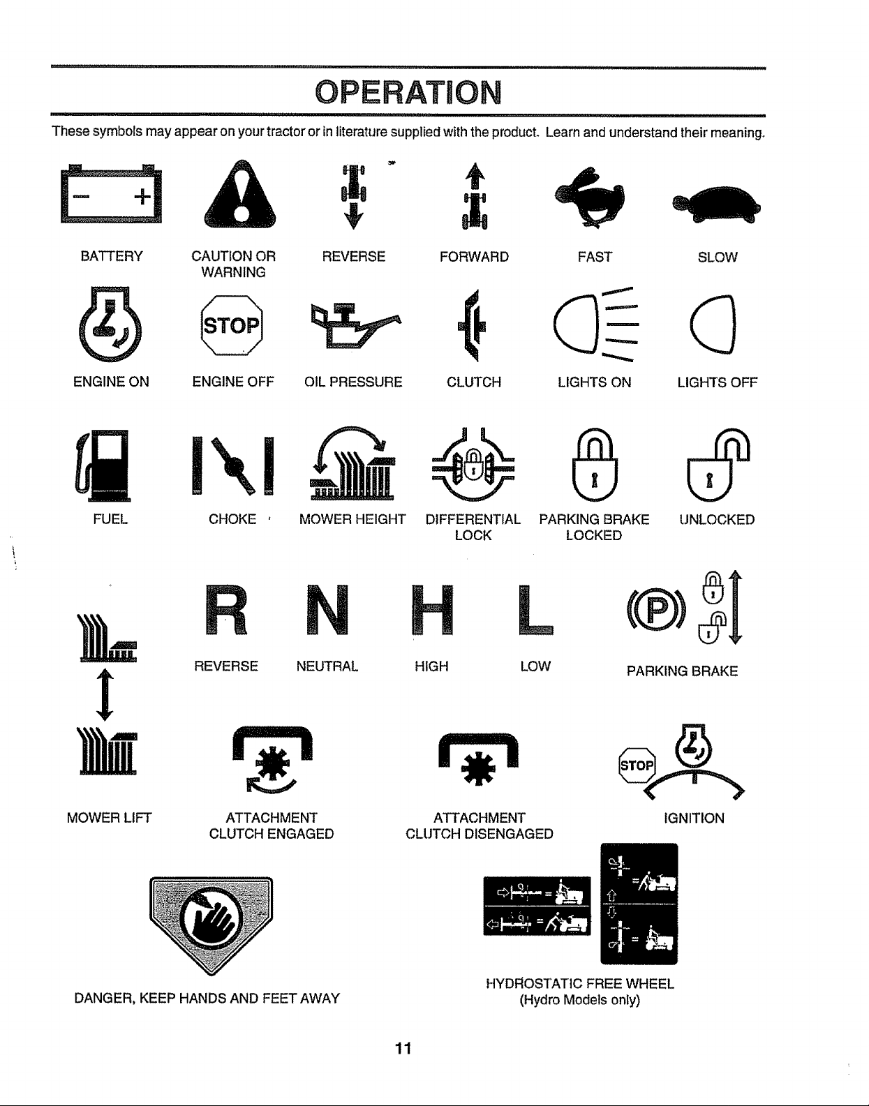
These symbols may appear on your tractor or in literature supplied with the product. Learn and understand their meaning.
BATTERY CAUTION OR REVERSE FORWARD FAST SLOW
WARNING
ENGINE ON ENGINE OFF OIL PRESSURE CLUTCH LIGHTS ON LIGHTS OFF
FUEL
MOWER LIFT
CHOKE ' MOWER HEIGHT DIFFERENTIAL PARKING BRAKE UNLOCKED
LOCK LOCKED
REVERSE NEUTRAL HIGH
ATTACHMENT
CLUTCH ENGAGED
ATTACHMENT
CLUTCH DISENGAGED
LOW PARKING BRAKE
IGNITION
DANGER, KEEP HANDS AND FEET AWAY
HYDROSTATIC FREE WHEEL
(Hydro Models only)
11
Page 12

OPERATION
llllll i i ill ii ill i i ii llllIHIHIHIHIHUlllll Ill ill ill ...................
KNOW YOUR TRACTOR
READ THIS OWNER'S MANUAL AND SAFETY RULES BEFORE OPERATING YOUR TRACTOR,
Compare the illustrationswithyourtractortofamdlarlze yourselfwiththe locationofvariouscontrolsand adjustments. Save
this manual for future reference.
CHOKECONTROL
LIGHT SWITCH
CLUTCH/BRAKE
PEDAL
HE|GHTADJUSTMENT
KNOB
AMMETER THROTTLE CONTROL
- CLUTCH SWITCH PLUNGER
ATTACHMENT LIFT LEVER
LIFTLEVER
tGNITION SWITCH
PARKING BRAKE
LEVER
SPEEDS:
3 MPH
!
FREE WHEEL CONTROL
Our'tractorsconform to the safety standards of the American National Standards Institute.
ATTACHMENTCLUTCH SWITCH- Usedtoengage mower'
blades or other attachments mounted to your tractor_
LIFTLEVER- Usedto raiseand lower mower deckorother
attachments mounted to yourtractor.
CLUTCH/BRAKE PEDAL - Used for declutching and
brakingthe tractor and starting the engine,
MOTION CONTROL - Selects the speed anddirectionof
tractor.
CHOKE CONTROL - Used when starting a coldengine.
LIGHT SWITCH - Turns the headlights on and off.
MORON
CONTROL
LEVER
FIG. 5
THRO'n'LE CONTROL - Used tocontrol engine speed.
FREEWHEEL CONTROL - Disengages transmissionfor
pushingor slowly towing the tractorwith the engine off.
IGNITION SWITCH - Used to start and stop the engine,
AMMETER - Indicates battery charging (+) or discharging
(-},
PARKING BRAKE LEVER - Locksclutch/brake pedalinto
the brake position°
HEIGHT ADJUSTMENT KNOB- Usedtoadjustthemower
heighL
12
Page 13
OPERATI
iii1_111,111 iii1_11,i i ................................................................. ................ I'/1/H_1I'111'11'1II II I
B_ in severe eye damage. Always wear.,safety glasses or eye shields while operating your tractor
i r_Ij The operation of any tractor can result in foreign objects thrown into the eyes, which can result
_ or performing any adjustments or repairs. We recommend a wide vision safety mask over the
i I I spectacles or standard safety glasses,
HOW TO USE YOUR TRACTOR
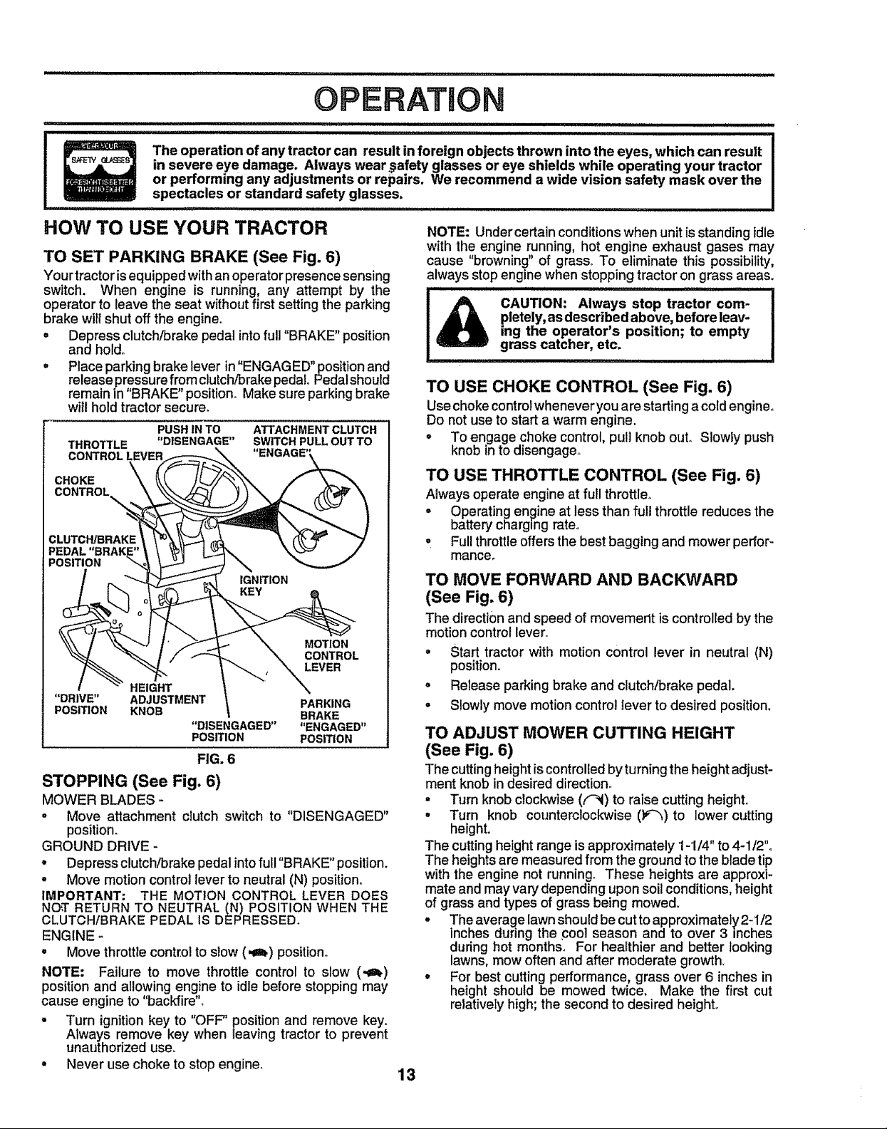
TO SET PARKING BRAKE (See Fig. 6)
Your tractor isequipped with an operator presence sensing
switch. When engine is running, any attempt by the
operator to leave the seat without first setting the parking
brake will shut off the engine,
= Depress clutch/brake pedal into full "BRAKE" position
and holdo
. Place parking brake lever in"ENGAGED" position and
release pressure from clutch/brake pedal Pedalshould
remain in"BRAKE" position. Make sure parking brake
wilt hold tractor secure.
PUSH IN TO ATTACHMENT CLUTCH
THROTTLE "DISENGAGE" SWITCH PULL OUT TO
CONTROL LEVER "ENGAGE'!
CHOKE
CONTROL
CLUTCH/BRAKE
PEDAL "BRAKE"
POSITION
IGNITION
MOTION
CONTROL
LEVER
HEIGHT
"DRIVE" ADJUSTMENT PARKING
POSITION KNOB BRAKE
STOPPING (See Fig. 6)
MOWER BLADES -
" Move attachment clutch switch to "DISENGAGED"
position.
GROUND DRIVE -
. Depress clutch/brake pedal into full "BRAKE" position.
• Move motion control lever to neutral (N) position_
IMPORTANT: THE MOTION CONTROL LEVER DOES
NO',TRETURN TO NEUTRAL (N) POSITION WHEN THE
CLUTCH/BRAKE PEDAL IS DEPRESSED.
ENGINE -
° Move throttle controlto slow (,€_) position.
NOTE: Failure to move throttle control to slow (,€_)
position and allowing engine to idle before stopping may
cause engine to "backfire",
- Turn ignition key to "OFF" position and remove key.
Always remove key when leaving tractor to prevent
unauthorized use.
° Never use choke to stop engine.
"DISENGAGED .... ENGAGED"
POSITION POSITION
FIG. 6
NOTE: Undercertain conditions when unit is standing idle
with the engine running, hot engine exhaust gases may
cause "browning" of grass° To eliminate this possibility,
always stop engine when stopping tractor on grass areas.
CAUTION: Always stop tractor com-
pletely, asdescribed above, before leav-
ing the operator's position; to empty
grass catcher, etc.
TO USE CHOKE CONTROL (See Fig. 6)
Use choke control whenever you are starting a cold engine.
Do not use to start a warm engine.
o To engage choke control, pull knob out, Slowly push
knob in to disengage°
TO USE THROTTLE CONTROL (See Fig. 6)
Always operate engine at full throttle°
• Operating engine at less than full throttle reduces the
battery charging rate°
,, Full throttle offers the best bagging and mower perfor-
mance.
TO MOVE FORWARD AND BACKWARD
(See Fig. 6)
The directionand speed of movernerlt is controlled by the
motion controllever_
° Start tractor with motion control lever in neutral (N)
position°
o Release parking brake and clutch/brake pedal.
• Slowly move motioncontrollever to desired position,
TO ADJUST MOWER CUTTING HEIGHT
(See Fig. 6)
The cuttingheight is controlledby turning the height adjust-
ment knob in desired direction_
- Turn knob clockwise (f-_) to raise cutting height,
• Turn knob counterclockwise (P_)to lower cutting
height.
The cutting height range is approximately 1-1/4" to 4-1/2"o
The heights are measured from the ground to the blade tip
with the engine not running. These heights are approxi-
mate and may vary depending upon soil conditions, height
of grass and types of grass being mowed.
° The average lawn should be cut to approximately 2-1/2
inches during the cool season and to over 3 inches
during hot months, For healthier and better looking
lawns, mow often and after moderate growth.
• For best cutting performance, grass over 6 inches in
height should be mowed twice. Make the first cut
relatively high; the second to desired height.
13
Page 14
illllllllllllllllll
i ii illllllllllllllllllllllllll i iill iiii ,IILll i illlll ,llll,l,i
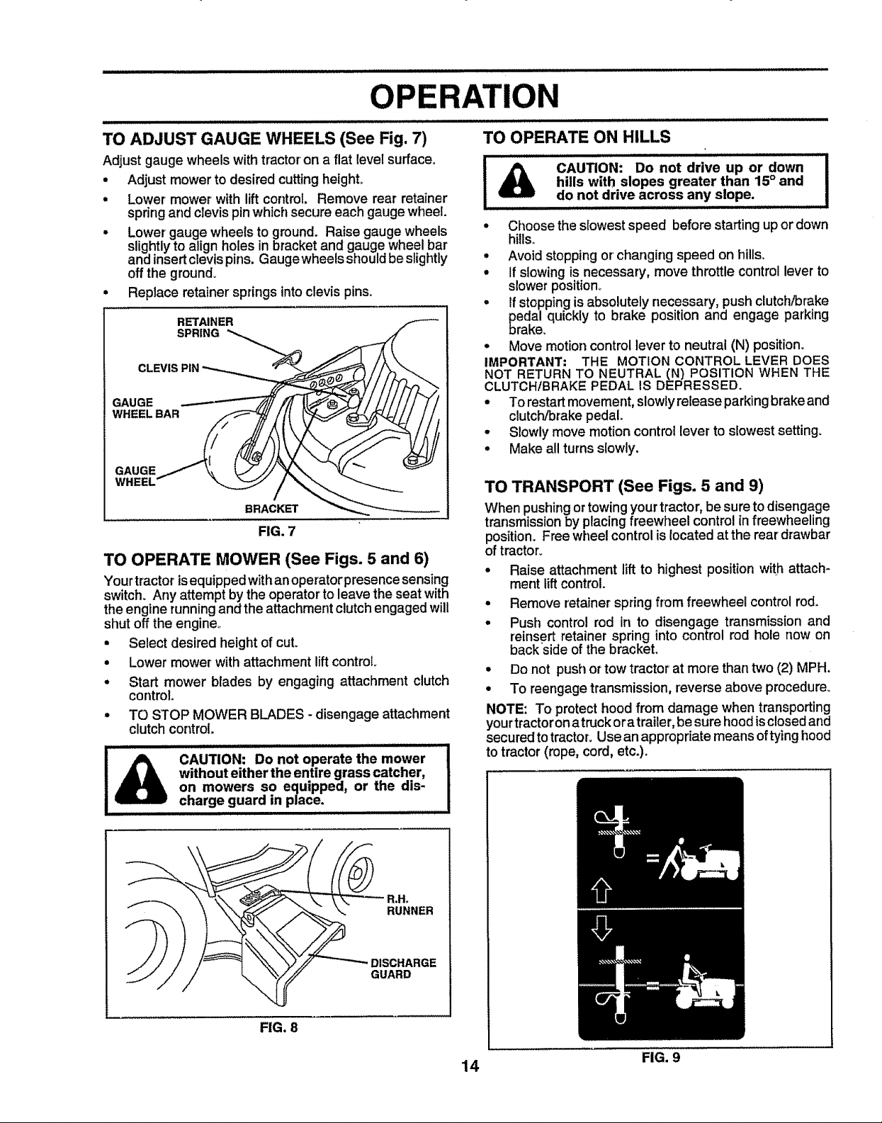
TO ADJUST GAUGE WHEELS (See Fig. 7)
Adjust gauge wheels with tractor on a flat level surface_
• Adjust mower to desired cutting height.
• Lower mower with lift control. Remove rear retainer
spring and clevis pin which secure each gauge wheel.
° Lower gauge wheels to ground. Raise gauge wheels
slightly to align holes in bracket and gauge wheel bar
and insert clevis pins. Gaugewheels should be slightly
off the ground°
• Replace retainer springs into clevis pins.
RETAINER
SPRING
CLEVIS PIN
GAUGE
WHEEL BAR
GAUGE
WHEEL
BRACKET
FIG. 7
TO OPERATE MOWER (See Figs. 5 and 6)
Yourtractorisequippedwithanoperatorpresencesensing
switch. Any attempt by the operator to leave the seat with
theengine runningand the attachment clutchengaged will
shut off the engine°
• Select desired height of cut.
• Lower mower with attachment liftcontrol
• Start mower blades by engaging attachment clutch
control.
• TO STOP MOWER BLADES - disengage attachment
clutch control.
without either the entire grass catcher,
.........illllllU I
I CAUTION: Do not operate the mower
i llllll lIH,H .............
on mowers so equipped, or the dis-
charge guard in place.
ATION
illll i ullll ill
TO OPERATE ON HILLS
!A °°°°'°""°° I
.......................do,,,notdrive across any slope. I
• Choose the slowest speed before starting up or down
hills°
° Avoid stopping or'changing speed on hills.
• If slowing is necessary, move throttle control lever to
slower position°
• if stopping is absolutely necessary, push clutch/brake
pedal quickly to brake position and engage parking
brake.
• Move motion control lever to neutral (N) position.
IMPORTANT: THE MOTION CONTROL LEVER DOES
NOT RETURN TO NEUTRAL (N) POSITION WHEN THE
CLUTCHIBRAKE PEDAL IS DEPRESSED.
• To restart movement,slowlyrelease parkingbrake and
clutch/brakepedal.
• Slowly move motion control lever to sEowestsetting.
• Make all turnsslowly,
TO TRANSPORT (See Figs. 5 and 9)
When pushingortowingyourtractor,be suretodisengage
transmissionby placing freewheel controlin freewheeling
position. Free wheel controlis located at the reardrawbar
of tractor_
. Raise attachment lift to highest position with attach-
mentlift control.
. Remove retainer spring from freewheel controlrod.
. Push control rod in to disengage transmission and
reinsert retainer spring into control rod hole now on
backside ofthe bracket,
= Do not push or tow tractor at more than two (2) MPH.
. To reengage transmission,reverse above procedure°
NOTE: To protect hoodfrom damage when transporting
yourtractoron atruckora trailer, be sure hoodisclosedand
secured totractor. Usean appropriate means oftying hood
to tractor (rope, cord, etc.).
hills with slopes greater than 15° and I
FIG. 8
DISCHARGE
GUARD
14 FIG,9
Page 15
OPERATI
BEFORE STARTLING THE ENGINE
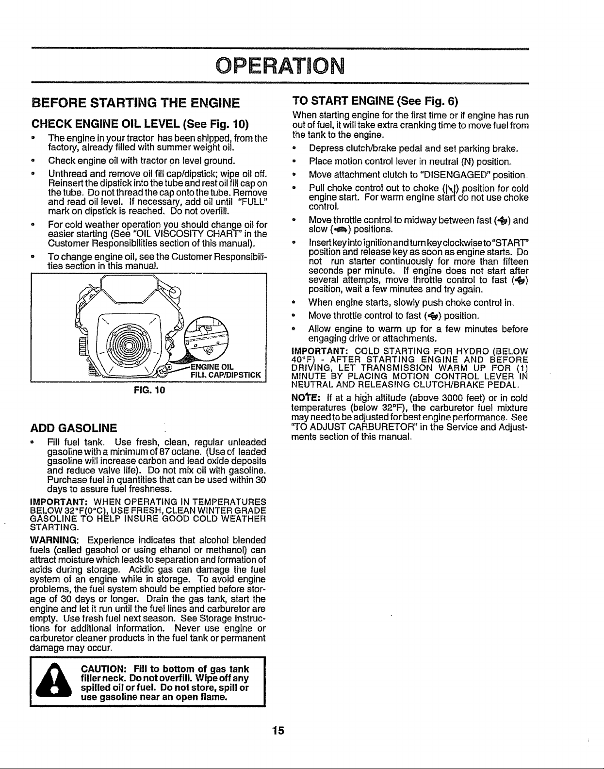
CHECK ENGINE OIL LEVEL (See Fig. 10)
. The engine inyourtractor has been shipped,fromthe
factory, already filled withsummer weight oil.
- Check engine oil with tractoron level ground.
o Unthread and remove oil fill cap!dipstick;wipe oil off°
Reinsertthedipstickintothetube and rest oilfill capon
thetube. Do notthread the cap ontothe tube. Remove
and read oil level° If necessary, add oil until "FULL"
mark on dipstick isreached. Do not overfill
o For cold weather operation you shouldchange oilfor
easier starting (See OIL VISCOSITY CHART' inthe
Customer Responsibilitiessectionof this manual).
° To change engine oil, seethe Customer Responsibili-
ties section inthis manual.
.ENGINE OIL
FILL CAP/DIPSTICK
FIG. 10
ADD GASOLINE
= Fill fuel tank. Use fresh, clean, regular unleaded
gasoline with a minimum of 87 octane.. (Use of leaded
gasoline will increase carbon and lead oxide deposits
and reduce valve life)o Do not mix oil with gasoline.
Purchase fuel in quantities that can be used within 30
days to assure fuel freshness.
IMPORTANT; WHEN OPERATING IN TEMPERATURES
BELOW 32°F(0°C), USE FRESH, CLEAN WINTER GRADE
GASOLINE TO HELP INSURE GOOD COLD WEATHER
STARTING°
WARNING: Experience indicates that alcohol blended
fuels (called gasohol or using ethanol or methanol) can
attract moisture which leads to separation and formation of
acids during storage° Acidic gas can damage the fuel
system of an engine while in storage. To avoid engine
problems, the fuel system should be emptied before stor-
age of 30 days or longer. Drain the gas tank, start the
engine and let it run until the fuel lines and carburetor are
empty. Use fresh fuel next season. See Storage instruc-
tions for additional information. Never use engine or
carburetor cleaner products in the fuel tank or permanent
damage may occur.
TO START ENGINE (See Fig. 6)
When starting engine for the firsttime or ifengine has run
out of fuel, it will take extra cranking time to move fuel from
the tank to the engine.
° Depress clutch/brake pedal and set parking brake°
• Place motion control lever in neutral (N) position.
° Move attachment clutch to "DISENGAGED" position.
• Pull choke controt out to choke (1\I) position for cold
engine start. For warm engine start do not use choke
control.
• Move throttle controlto midway between fast (,_) and
slow (,II) positions°
• lnsert key into ignitionand turn keyclockwise to"START"
positionand release key as soon as engine starts. Do
not run starter continuously for more than fifteen
seconds per minute. If engine does not start after
several attempts, move throttle control to fast (,_)
position, wait a few minutes and try again.
• When engine starts, slowly push choke control in.
° Move throttle control to fast (,_) position..
° Allow engine to warm up for a few minutes before
engaging drive or attachments.
IMPORTANT= COLD STARTING FOR HYDRO (BELOW
40 F) - AFTER STARTING ENGINE AND BEFORE
DR|VING, LET TRANSMISSION WARM UP FOR (1)
MINUTE BY PLACING MOTION CONTROL LEVER IN
NEUTRAL AND RELEASING CLUTCH/BRAKE PEDAL,.
NOTE: If at a high altitude (above 3000 feet) or in cold
temperatures (below 32°F), the carburetor fuei mixture
may need to be adjustedfor best engine performance. See
"TO ADJUST CARBURETOR" in the Service and Adjust-
ments section of this manual°
filler neck. Do not overfill. Wipe offany
I_ CAUTION: Fill to bottom of gas tank
spilled oil orfuel Do not store, spill or
use gasoline near an open flame.
'15
Page 16
OPERATION
................................. i iIIIIIHI I IIlllllll
PURGE TRANSMISSION
CAUTION: Never engage or disengage
IA...........
To ensure proper operation and performance, it is recom-
mended that the transmission be purged before operating
tractor for the first time+ This procedure will remove any
trapped air inside the transmission which may have devel-
oped during shipping of your tractor.
IMPORTANT: SHOULD YOUR TRANSMISSION REQUIRE
REMOVAL FOR SERVICE OR REPLACEMENT, IT
SHOULD BE PURGED AFTER RE1NSTALLATION
BEFORE OPERATING THE TRACTOR.
• Place tractor safely on level surface with engine off and
parking brake set..
• Disengage transmission by placing freewheel control
in freewheeling position (See 'q"O TRANSPORT" in
this section of manual).
• Sitting tnthetractor seat, startengine+ Afterthe engine
is running, move throttle control to slow (,il) position.
With motion control lever in neutral (N) position, slowly
disengage clutch/brake pedal.
° Move motion control lever to full forward position and
hold for five (5) seconds. Move lever to full reverse
position and hold for five (5) seconds° Repeat this
procedure three (3) times.
NOTE: During this procedure there will be no movement of
drive wheels. The air is being removed from hydraulic drive
system+
• Move motion control leverto neutral (N)position° Shut-
off engine and set parking brake.
° Engage transmission by placing freewheel control in
driving position (See "TO TRANSPORT" in this section
of manual).
° Sitting inthetractor seat, startengine. Aftertheengine
is running, move throttle control to half (1/2) speed.
With motion control lever inneutral (N) position, slowly
disengage clutcPvbrake pedal.
° Slowly move motion control lever forward, after the
tractor moves approximately five (5) feet, slowly move
motion control lever to reverse position. After the
tractor moves approximately five(5) feet return the
motion control lever tothe neutral (N) position. Repeat
this procedure with the motion control lever three (3)
times.
• Your tractor is now purged and now ready for normal
operation.
freewheel lever while the engine is run-
ning.
MOWING TIPS
° Tire chains cannot be used when the mower housing
is attached to tractor.
• Mower should be properly leveled for best mowing
performance. See "TO LEVEL MOWER HOUSING" in
the Service and Adjustments section of this manual.
• Use the runner on the right hand side of mower as a
guide. The blade cuts approximately an inch outside
the runner (See Fig. 8)_
• The teft hand side of mower should be used for+trim-
ming+
° Drive so that ctippings are discharged onto the area
that has been cut. Have the cut area to the rightof the
tractor. This will result in a more even distribution of
clippings and more uniform cutting.
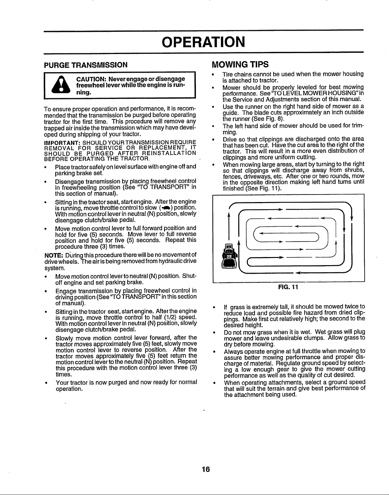
° When mowing large areas, start by turning to the right
so that clippings will discharge away from shrubs,
fences, driveways, etc. After' one or two rounds, mow
in the opposite direction making left hand tums until
finished (See Fig..11).
f .................
FIG. 11
• If grass is extremely tall, it should be mowed twice to
reduce load and possible fire hazard from dried clip-
pings. Make first cut relatively high; the second to the
desired height.
° Do not mow grass when it is wet. Wet grass wilt plug
mower' and leave undesirable clumps. Allow grass to
dry before mowing.
° Always operate engine at full throttle when mowing to
assure better mowing performance and proper dis-
charge of material Regulate ground speed by select-
ing a low enough gear to give the mower cutting
performance as welt as the quality of cut desired.
• When operating attachments, select a ground speed
that will suit the terrain and give best performance of
the attachment being used.
16
Page 17
CUSTOMER R BILITHES
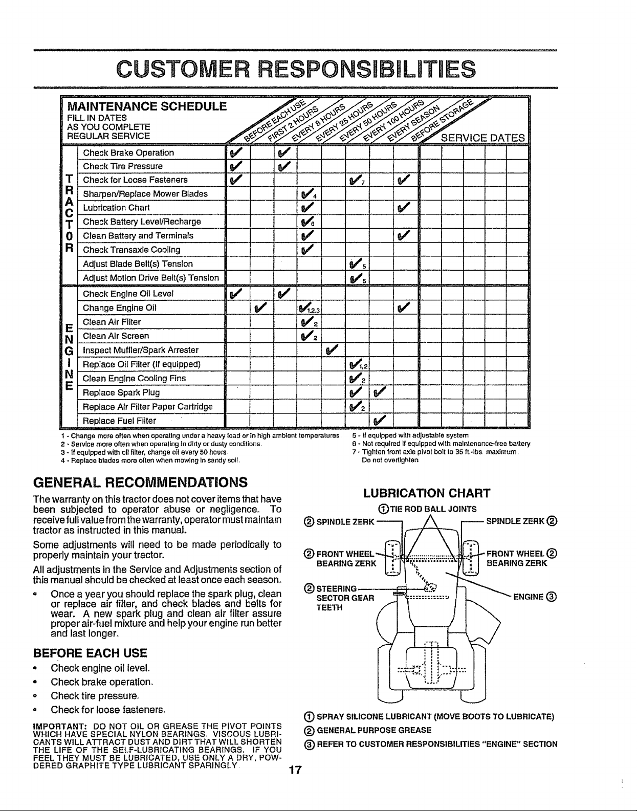
MAINTENANCE SCHEDULE r'_i_____
FILL IN DATES _ _ _,'_.' ,-t_ _O ;,_ _£,-_ ._
AsYOUCOMPL
REGULAR..SERV!C E........................................ CE DATES
Check Brake Operation __ , ,6# #' ,
CheckTire Pressure I_ if
T Checkfor LooseFasteners 64r _#'7
R Sha_e_Replace MowerBlades _4
c L"brtc'iionCh"" " 1 1 I iii1: ,V'......
T CheckBatteryLevellRecharge .64_6.........
0 Clean BatteryandTerminats 6## ...... ' ' "_ .... . ....
R CheckTransaxleCoollng ..... _#' ............
Adjust BladeBelt(s)Tension 6##s
Adjust MotionDriveBelt(s-)Tension yes .........................
:......_::.....
CheckEngineOil Level
ChangeEngineeli
CleanAir Filter
E
N
G InspectMuffler/SparkArrester
i Replace Oil Filter (If equipped)
N 'ciean Engtne,,CoolingFins
Replace Spark Plug
Replace Fuel Fflter
1 * Change more or[tenwhen operetlng under a heavy toad or in high ambient temperalurss,,
2 - Service more often when operating in dtdy or dusty conditions
3 - If equ{pped wiih oILfilter, change oil every 50 hours
4 - Replace blades more often when mowing tn sandy soil,
GENERAL RECOMMENDATUONS
The warranty on this tractor does not cover items that have
been subjected to operator abuse or negligenceo To
receive full value from the warranty, operator must maintain
tractor as instructed in this manual.
Some adjustments will need to be made periodically to
properly maintain your tractor.
All adjustments in the Service and Adjustments section of
this manual should be checked at least once each season,,
Once a year you should replace the spark plug, clean
or replace air filter, and check blades and belts for
wear. A new spark plug and clean air filter assure
proper air-fuel mixture and help your engine run better
and last longer.
BEFORE EACH USE
. Check engine oil level
o Check brake operation°
° Checktire pressure.
° Check for loose fastener&
IMPORTANT: DO NOT OIL OR GREASE THE PIVOT POINTS
WHICH HAVE SPECIAL NYLON BEARINGS, VISCOUS LUBRI-
CANTS WILL ATTRACT DUST AND Dt RT THAT WILL SHORTEN
THE LIFE OF THE SELF-LUBRICATING BEARINGS. IF YOU
FEEL THEY MUST BE LUBRICATED, USE ONLY A DRY, POW-
DERED GRAPHITE TYPE LUBRICANT SPARINGLY.
5 - I! equipped wi_hadjustable system
6 - Not requlredIf equipped with malntenance4ree battery
7 - Tighten front axis pivot belt to 35 ft4bs maximum,
Do not oveMIghten,
LUBRICATION CHART
(_TIE ROD BALL JOINTS
®
t_ SPINDLE ZERK ®
®
BEARINGZERK -._W_...BEARINGZERK
®
TEETH
(_ SPRAY SILICONE LUBRICANT (MOVE BOOTS TO LUBRICATE)
® GENERAL PURPOSE GREASE
(_) REFER TO CUSTOMER RESPONSIBILITIES "ENGINE" SECTION
17
_,,J,4"FRONTWHEEL®
ENGINE ®SECTOR GEAR :::::::::::': :'
Page 18
CUSTOMER RESPONSIBILITIES
TRACTOR
Always observe safety rules when performing any mainte-
nanceo
BRAKE OPERATION
If tractor requires more than six (6) feet stopping distance
at high speed in highest gear, then brake must beadjusted.,
(See "TO ADJUST BRAKE" i.n'the.Sbr_ice and AdjrJ_3F
ments section of this manua])o
TIRES
Maintain proper air pressure in all tires (See "PROD-
UCT SPECIFICATIONS" on page 3 of this manual)._
o
Keep tires free of gasoline, oil, or insect control chemi-
cals which can harm rubber.
o
Avoid stumps, stones, deep ruts, sharp objects and
other hazards that may cause tire damage.
BLADE CARE
For best results mower blades must be kept sharp. Re-
place bent or-damaged blades.
BLADE REMOVAL (See Fig. 12)
• Raise mower to highest position to allow access to
blades.
• Remove hex bolt, lockwasher and flat washer securing
blade.
° Install new or resharpened blade with trailing edge up
towards deck as shown.
° Reassemble hex bolt, lock washer and flat washer in
exact order as shown.
= Tighten bolt securely (30-35 Ft. Lbs. torque).
IMPORTANT: BLADE BOLT ISGRADE 8 HEATTREATED.,
NOTE: We donot recommend sharpening blade- but ifyou
do, be sure the blade is balanced.
*A GRADE 8 HEAT TREATED BOLT CAN BE
IDENTIFIED BY SIX LINES ON THE BOLT HEAD.
FIG. 12
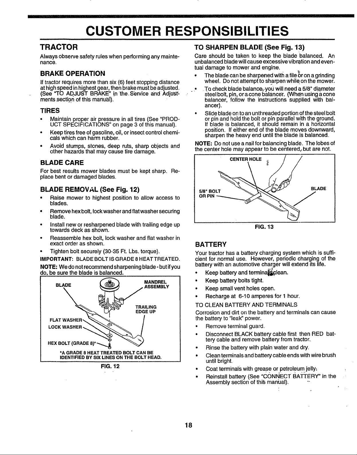
TO SHARPEN BLADE (See Fig. 13)
Care should be taken to keep the blade balanced, An
unbalancedblade willcause excessivevibrationand even-
tual damage to mower' and engine,
• The blade canbe sharpenedwith a file _r on a grinding
wheel. Do not attempt tosharpen while,on the mower.
s
T.Q check blade balance,you will needa 5/8" diameter
steel bolt, pin,oracone balance'r. (When usingacone
batancer, follow the instructions supplied with bal-
ancer).
° Slideblade ontoan unthreaded portionof the steel bolt
or pinand hold the boltor pin parallel with the ground.
If blade is balanced, it should remain in a horizontal
position. If either end of the blade moves downward,
sharpen the heavy end untilthe blade is balanced,.
NOTE: Do notuse anail for' balancing blade. The lobesof
the center hole may appear tobe centered,, but are not.
FIG. 13
BATTERY
Your tractor has a battery charging system which is suffi-
cient for normal use_ However, periodic charging of the
battery with an automotive charger willextend itslife.
° Keep batteryand termin_lean.
° Keep battery bolts tighL
° Keep small vent holes open_
• Recharge at 6-10 amperes for 1 hour_
TO CLEAN BATTERY AND TERMINALS
Corrosion and dirt on the battery and terminals can cause
the battery to "leak" power'.
• Remove terminal guard..
• Disconnect BLACK battery cable first then RED bat-
tery cable and remove battery from tractor.
o Rinse the battery with plain water and dry°
° Clean terminals and battery' cable ends with wire brush
until bright.
• Coat terminals with grease or pet_'oleumjelly;
° Reinstall battery (See "CONNECT BATTERY" in the
Assembly section of thi_ maniJal)_ -_
'
18
Page 19

BILITJES
TRANSAXLE COOLING
The fan and cooling fins of transmission should be kept
clean to assure proper cooling.
Do not attempt to clean fan or transmission while engine is
running or while the transmission is hot. To prevent
possible damage to seals, no not use high pressure water
or steam to clean transaxle.
o inspect cooling fan to be sure fan blades are intactand
clean.
° Inspect cooling fins for dirt, grass clippings and other
materials. To prevent damage to seals, do not use
compressed air or high pressure sprayer°
TRANSAXLE PUMP FLUID
The transaxle was sealed at the factory and fluid mainte-
nance is not required for the life of the transaxle. Should
the transaxle ever leak or require servicing, contact your
nearest authorized service center/departmento
V-BELTS
Check V_belts for deterioration and wear after 100 hours of
operation and replace if necessary° The belts are not
adjustable_ Replace belts if they begin to slip from wear.
ENGINE
TO CHANGE ENGINE OIL (See Figs. '14 and 15)
Determine temperature range expected before oil change.
All oil must meet API service classification SF or SGo
° Be sure tractor is on level surface,,
. Oi! willdrain more freely when warm,,
• Catch oil in a suitable container,,
• Remove oil fill cap!dipsticko Becareful not to allow dirt
to enter the engine when changing oil
° Remove drain plugo
• After oil has drained completely, replace oil drain plug
and tighten securely.
= Refill engine with oil through oil fill dipstick tube. Pour
slowly. Do not overfill° For approximate capacity see
"PRODUCT SPECIFICATIONS" on page 3 of this
manual.
° Use gauge on oilfill cap/dipstick for checking level. Be
sure dipstick is in all the way for accurate reading,
Keep oil at "FULL" line on dipstick,
AIRSCREEN OIL DRAINPLUG
\
LUBRICATION
Only use high quality detergent oil rated with API service
classificationSForSG_ Selectthe oilsSAEviscositygrade
according to your expected operatingtemperature.
SAE VISCOSITY GRADES
_F -20* 0 = 30 _ _?o 40 = 60 o 80_ 100,
% -so'...... -2o° -lo" . . o° 1o° .....20, ..3o".. 40°
TEMPERATURE RANGE ANT_CIPATED BEFORE NEXT OiL CHANGE
FIG. 14
NOTE: Although multi-viscosity oils (5W30, ! 0W30, etc.)
improves starting in cold weather, these multi-viscosity oils
will result in increased oil consumption when used above
32"C. Check your engine oil level more frequently to avoid
possible engine damage from running low on oil
Change the oil after the first two hours of operation and
every 50 hours thereafter or at least once a year if the
tractor is not used for 50 hours in one year°
Check the crankcase oil level before starting the engine
and after each eight (8) hours of continuous use_
ENGINE OIL
FILL CAP/DIPSTICK
FIG. 15
CLEAN AIR SCREEN (See Fig. 15)
Air screen must be kept free of dirt and chaff to prevent
engine damage from overheating. Clean with a wire bnJsh
or compressed air to remove dirt and stubborn dried gum
fibers.
19
Page 20

CUSTOMER R
.................................. =l ,=,,i,l,= i LHlU,U,t
CLEAN AIR INTAKE/COOLING AREAS
To insure proper cooling, make sure the grass screen,
cooling fins, and other external surfaces of the engine are
kept clean at all times.
Every 100 hours of operation (more often under extremely
dusty, dirty conditions), remove the blower housing and
other cooling shrouds. Clean the cooling fins and external
surfaces as necessary° Make sure the cooling shrouds are
reinstalled.
NOTE: Operating the engine with a blocked grass screen,
dirty or plugged cooling fins, and/or cooling shrouds re-
moved will cause engine damage due to overheating_
AIR FILTER (See Fig. 16)
Your engine will not run properly using a dirty air filter_
Clean the foam pro-cleaner after every 25 hours of opera-
tion or every season. Service paper cartridge every 100
hours of operation or every season, whichever occurs first.
Service air cleaner more often under dusty conditions°
• Loosen knob and remove cover°
TO SERVICE PRE-CLEANER
• Slide foam pro-cleaner off cartridge.
° Wash it in liquid detergent and water.
• Squeeze it dry in a clean cloth.
• Saturate it in engine oil. Wrap it in clean, absorbent
cloth and squeeze to remove excess oil
TO SERVICE CARTRIDGE
• Remove nut and cartridge plate°
° Gently tap the flat side of the paper cartridge to dis-
lodge dirt. Do not wash the paper cartridge or use
pressurized air, as this will damage the cartridge.
Replace a dirty, bent, or damaged cartridge°
, Reinstall the pro-cleaner (cleaned and oiled) over the
paper cartridge°
• Check rubber seal for damage and proper position
around stud° Replace if necessary°
° Reassemble air cleaner', cartridge plate, and nuL
° Reinstall air cleaner cover and secure by tightening
knob.
CARTRIDGE
....................................... ,,,,,,,,,,,
ENGINE OIL FILTER
RepIacethe engine oil filter every season or every otheroil
change if the tractoris used more than 100 hours in one
year.
MUFFLER
Inspectand replacecorroded muffler and spark attester (if
equipped) as it couldcreate a fire hazard and/or damage.
SPARK PLUGS
Replace spark p_ugsat the beginning of each mowing
season or' after every 100 hours of operation, whichever
occurs first. Spark pEugtype and gap setting are shown in
"PRODUCT SPECIFICATIONS" on page 3 of this manual
IN-LINE FUEL FILTER (See Fig. 17)
The fuel filter shouldbereplaced once each season_ Iffuel
filter becomes clogged, obstructingfuel flow to carburetor',
replacement is required.
• With engine cool, remove filter and plug fuel line
sections_
° Place new fuel filter in position in fuel line with arrow
pointingtowards carburetor.
• Be sure there are no fuel line leaks and clamps are
properly positioned.
° Immediatelywipe up any spilled gasoline.
CLAMP
CLAMP FUEL RLTER
FIG. 17
CLEANING
° Clean engine, battery, seat, finish, etc. of all foreign
matter.
• Keep finished surfaces and wheels free of all gasoline,
oil, etc.
• Protect painted surfaces with automotive type wax.
We do not recommend using a garden hose to clean your
tractor unless the electrical system, muffler, air' filter and
carburetor are covered to keep water out. Water inengine
can result in a shortened engine life.
FIG. 16
RUBBER
SEAL
20
Page 21

ERVICE AND ADJUSTMENTS
i ±| i H,,,m_l_
CAUTION: BEFORE PERFORMING ANY SERVICE OR ADJUSTMENTS:
o Depress clutch/brake pedal fully and set parking brake.
° Place motion control lever inneutral (N) position.
° Place attachment clutch in "DISENGAGED" position.
o Turn ignition key "OFF" and remove key.
o Make sure the blades and all moving parts have completely stopped,
° Disconnect spark plug wire from spark plug and place wire where it cannot come in contact with
.............plug.......................................................
TRACTOR
TO REMOVE MOWER (See Fig. 18)
° Place attachment clutch in "DISENGAGED" position_
° Turnheight adjustment knob to lowest setting.
° Lower mower to its lowest position.
" sRie_°v_ r_tai_t_iSsPn; g ;e°Idinr_gs,anat__owaybar t°rChkae_:
o _ee_OaVned_tsaeinn;rgSp_nmgS_om dSeUcSkPensionarms at
= Raise attachment lift to its highest position,,
° Remove two retainer springs from each front link and
remove links.
= Slide mower forward and remove belt from electric
clutch pulley.
° Slide mower out from under right side of tractor,
IMPORTANT: IF AN ATTACHMENT OTHER THAN THE
MOWER DECK IS TO BE MOUNTED ON THE TRACTOR,
REMOVE THE FRONT LINKS_
TO INSTALL MOWER
Follow procedure described in "INSTALL MOWER AND
DRIVE BELT" in the Assembly section of this manual
FRONT
SUSPENSION
SUSPENSION ADJUSTMENT
UFT
LINKS
TO LEVEL MOWER HOUSING
Adjust the mower whiletractor is parked on level ground or
driveway. Make sure tires are properly inflated (See
"PRODUCT SPECIFICATIONS" on page 3 of this manual).
Iftires are over or undednflated, you will not properly adjust
your mower,
SIDE-TO-SIDE ADJUSTMENT (See Figs. 18 and 19)
° Raise mower to its highest position.
° Measure height from bottom of deck curl to ground
level at front corners of mower,, Distance "A" on both
sides of mower should be the same.
° If adjustment is necessary, make adjustment on one
side of mower only.
° To raise one side of mower, tighten lift link adjustment
nut on that side.
o To lower one side of mower, loosenlift link adjustment
nut on that side.
NOTE: Each halfturn of adjustment nut will change mower
height about 3/16",,
Recheck measurements after adjusting.
BOTTOM BOTTOM
OF CURL OF CURL
ANTI-SWAY RETAINER
BAR SPRINGS
FIG. 18
21
Page 22

E AND ADJUSTMENTS
......................................... •....................... illll iiUlll
FRONT-TO-BACK ADJUSTMENT (See Figs. 20 and21)-
IMPORTANT: DECK MUST BE LEVEL SIDE-TO-SIDE. IF
THE FOLLOWING FRONT-TO-BACK ADJUSTMENT IS
NECESSARY, BE SURETO ADJUST BOTH FRONT LINKS
EQUALLYSO MOWER WILL STAY LEVELSIDE-TO-SIDEo
To obtain the best cutting results, the mower' housing
should be adjusted sothe front is approximateIy 1/8" to 1/2"
lower than the rear when the mower is in its highest
position.
Check adjustment on rightside of tractor_ Measure dis-
tance "F" directly in front of and behind the mandrel at
bottom edge of mower housing as shown.
• Before makinganynecessary adjustments, checkthat
both front links are equal in length.
• If linksare notequal in length, adjust one link to same
length as other linko
• To lowerfront ofmower'housing,loosennut"G"on both
front linksan equal number ofturns.
• When distance "F" is 1/8" to 1/2" lower at front than
rear,tighten nut"H" againsttrunniononbothfront links.
• To raise front of mower housing, loosen nut "H" from
trunnion on both front links. Tighten nut "G" on both
front links an equal number of turns.
• When distance "F" is 1/8" to 1/2" lower at front than
rear, tighten nut "H" against trunnion on both front
links.
NOTE: Each full turn of nut "G" will change dim° "F" by
approximately 3/8"o
• Recheck side-to-side adjustment.
% \ . oo . MANDREL
TO REPLACE MOWER DRIVE BELT
MOWER DRIVE BELT REMOVAL (See Fig. 22) -
o
Park tractor on a level surface. Engage parking brake,
Remove four screws from L.H. mandrel cover and
remove cover'.
• Roll belt over the top of L.H_mandrel pulley.
• Remove belt from electdc clutch pulley_
• Remove belt from idler pulleys.
• Remove any dirt or grass clippings which may have
accumulated around mandrels and entire upper deck
surface.
• Check primary idler'armand two idlersto see that they
rotate freely,.
° Be sure spdng is Securely hooked to primary idler arm
and bolt in mower' housing.
MOWER DRIVE BELT INSTALLATION (See Fig. 22) -
• Install belt in both idlers. Make sure bett is in both bett
keepers at the idlers as shown.
• Install new belt onto electric clutch pulley.
• Roll belt into upper groove of L.H, mandrel pulley.
• Carefully check belt routing making sure belt is in the
grooves correctly and inside belt keepers.
• Reassemble L.H, mandrel cover_
L.H, SCREWS SPRING CLUTCH
MANDREL PULLEY
COVER IDLER
PULLEYS
PRIMARY
IDLER
ARM
ELECTRIC
FIG. 20
BOTH FRONT LINKS SHOULD BE EQUAL IN LENGTH
FRONT LINKS
FIG. 21 22
MANDREL
MOWER
DRIVE BELT
BOLT IN
MOWER
HOUSING
BELT
KEEPER
FIG. 22
Page 23

RVmCEAND ADJUSTMENTS
i L ' lll'l..............
TO REPLACE MOWER BLADE DRIVE BELT
(See Fig. 23)
Park the tractoron level surface_ Engage parkingbrake,,
° Remove mowerdrivebelt(See'`TO REPLACEMOWER
DRIVE BELT_ inthis sectionof thismanual),
° Remove mower (See "TO REMOVE MOWER" inthis
section of thismanual).
° Remove four screws from R°Homandrel cover and
remove cover. Unhook spring from bolt on mower
housing°
° Carefully roll belt off R.Homandrel pulley.,
° Remove belt from center mandrelpulley, idler pulley,
and LoHomandrel pulley,
° Remove any dirt or grass which may have accumu-
lated aroundmandrels and entire upper deck surface..
, Check secondary idler arm and idler to see that they
rotate freely,.
° Be sure spring is hooked in secondary idlerarm and
sway-bar bracket.
° Install new belt in lower groove of L,.Homandrel pulley,
idler pulley, and center mandrel pulley as shown°
= Roll belt over Ro.H,,mandrel pulley. Make sure belt isin
all grooves properly_
o Reconnect spring to bolt in mower housing and rein-
staleRoll° mandrel cover_
, Reinstall mower to tractor (See "INSTALL MOWER
AND DRIVE BELT" in the Assembly section of this
manual).
O
Reassemble mower drive belt (See '`TO REPLACE
MOWER DRIVE BELT" in this section of this manual).
LH.
SECONDARY
IDLER ARM
MOWER BLADE
DRIVE BELT
CENTER
MANDREL
MANDREL
COVER
NOTE: After installinga new electric clutch, run tractor at
full throttle and engage and disengage electric clutch 10
cycles to wear inclutch plate,
NYLONLOCKNUT(3)
FIG. 24
BRAKE PLATE
TO ADJUST BRAKE (See Fig. 25)
Your tractor is equippedwith an adjustable brake system
whichis mountedon the side of the transaxle.
Iftractor requires more than six (6) feet stopping distance
at high speed inhighest gear, then brake must beadjusted,
• Depress clutch/brake pedaland engage parking brake°
°
Measure distance between brake operating arm and
nut "A" on brake rod.
o
If distance isother than 1-1/2", loosen jam nut and turn
nut "A" until distance becomes 1-1/2". Retighten jam
nut against nut "A"o
Road test tractor for proper stopping distance as stated
above. Readjust ifnecessary° If stopping distance is
still greater than six (6) feet in highest gear, further
maintenance is necessary. Contact your nearest au-
thorized service centeddepartmento
WITH PARKING BRAKE "ENGAGED"
NUT "A"
JAM NUT
SWAY-BAR IDLER
BRACKET PULLEY
FIG. 23
TO ADJUST ATTACHMENT CLUTCH
(See Fig. 24)
The electric clutch should provide years of service, The
clutch has a built-in brake that stops the pulley within 5
seconds, Eventually, the internal brake wil! wear which
may cause the mower blades to not engage, or, tonot stop
as required° Adjustments should be made byyour nearest
authorized service center/department.
° Make sure attachment clutch and ignition switches are
in "OFF" position°
° Adjust the three nylon locknuts until space between
clutch plate and rotor measures .012" at all three slot
locations cut in side of brake plate°
OPERATING
ARM
FIG. 25
23
Page 24

AND ADJUSTMENTS
TO REPLACE MOTION DRIVE BELT
(See Fig. 26)
Park the tractoron level surface. Engage parkingbrake.
Forease ofservicethere isa beltinstallationguidedecalon
bottom of leftfootrest,
• Remove mower (See "TO REMOVE MOWER" in this
section of this manual..)
BELT REMOVAL -
° Engage parking brake (creates slack in belt).
° Remove belt from clutching and fan idler pulleys.
= Remove belt from transaxle pulley.
= Remove belt from engine pulley and front V-idler
pulley.
° Pull belt out of all belt keepers and remove from tractor.
BELT INSTALLATION -
= Place V part of belt intogrooves on engine pulley and
front V-idler, making sure to route belt insideof all belt
keepers°
° Route belt on right side, coming from V-idler, towards
back of tractor, above midspan belt keeper and to top
of transaxle pulley.
° Route belt on left side, coming from engine pulley,
towards back of tractor and through loop in midspan
belt keeper.
• Place V part of belt into grooves on transaxle and fan
idler pulleys, making sure to route belt insideof all belt
keepers.
° Place belt around clutching idlers as shown, making
sure to route belt inside of all belt keepers.
° Check to be sure belt is positioned correctly and is on
proper side of all belt keepers_
° Reinstall mower°
IMPORTANT: CHECK BRAKE ADJUSTMENT..
TRACTOR V-BELT DRIVE SCHEMATIC
VIEWED FROM LH. SIDE OF TRACTOR
CLUTCHING IDLER BELT
FLAT
CLUTCHING TRANSAXLE
TO ADJUST MOTION CONTROL LEVER
(See Fig. 27)
The motion controllever'has been preset atthe factory and
adjustmentshould not be necessary.
If for any reason the motion control lever will not hold its
positionwhileat a selected speed, itmay be adjustedat the
friction pack located on the rightside ofchassis.
• Park tractoron level surface° Stop tractor by turning
ignition key to "OFF" position and engage parking
brake,
° Place motion control lever in neutral (N) position_
• While holding Iocknut, loosen jam nut
° Tighten Iocknut1/4 turn.
° While holdingIocknut, tightenjam nut securely.
NOTE: If for any reason the effort to move the motion
controlIever becomes too excessive, reverse the above
adjustment procedure by loosening locknutI/4 turn.
Road testtractorafter'adjustment and repeat procedureif
necessary.
LOCKNUT
JAM NUT
FIG. 27
ENGINE ABOVE BELT
PULLEY
V-IDLER KEEPER
AS VIEWED FROM BOTTOM
FIG. 26
BELT
TWISTS
BELT
KEEPER
FAN
IDLER
TRANSMISSION REMOVAL/REPLACEMENT
Should your transmission require removal for service or
replacement, it shouldbe purged after reinstaUationbefore
operating the tractor. See "PURGE TRANSMISSION" in
Operation section of this manual.
TO ADJUST STEERING WHEEL ALIGNMENT
tf steering wheelcrossbarsare not horizontal (left to right)
when wheelsare positionedstra{ghtforward, removesteer-
ingwheel and reassembleper instructionsintheAssembly
section of this manual.
24
Page 25

S
AND
FRONT WHEEL TOE-IN ADJUSTMENT
Front wheel toe-in is required for proper steering operation.
Toe-in was set atthe factory and adjustment should not be
necessary. If parts in the front axle or steering mechanism
have been replaced or damaged, check toe-in and adjust
if necessary..
TO CHECK TOE-IN (See Fig_28) -
o Position front wheels straight ahead°
, Measure distance between wheels at front and rear of
tires (dimensions "A" and "B")_
° Front dimension "A" should be 1/8" to 1/4" less than
rear dimension "B"°
TO ADJUST TOE-IN (See Figs. 28 and 29) -
• Loosen jam nuts at adjustment sleeves on tie rod°
° Adjusttie rod until dimension "A"is 1/8" to 1/4" lessthan
dimension "B".
, Tighten jam nuts securely.
= B....... I
AD, !NTS
RETAINING
RING
AXLE
COVER
FIG. 30
REAR WHEEL -
" Block rear axle securely°
• Remove five (5) hub bolts to allow wheel removal.
° Repair tire and reassemble. Replace and tighten hub
bolts securely.
TO START ENGINE WITH A WEAK BATTERY
(See Fig. 31)
ate explosivegases. Keepsparks, flame
and smoking materials away from bat-
CAUTION: Lead-acid batteries gener-
teries. Always wear eye protection
when around batteries.
_----- A------H
FIG. 28
ADJUSTMENT
!SLEEVES
JAM
TIE ROD
FIG. 29
FRONT WHEEL CAMBER
The front wheel camber isnot adjustable on your tractor, If
damage has occurred to affect the front wheel camber,
contact your nearest authorized service center/depart-
ment°
TO REMOVE WHEEL FOR REPAIRS
FRONT WHEEL (See Fig. 30) -
° Block up axle securely°
° Remove axle cover, retaining ring and washers to allow
wheel removal.
• Repair tire and reassemble°
° Replace washers and snap retaining ring securely in
axle groove.
o Replace axle cover..
If your battery istoo weak to start the engine, it should be
recharged, if "jumper cables" are used for emergency
starting, follow this procedure:
IMPORTANT: YOUR TRACTOR ISEQUIPPED WITH A 12
VOLT NEGATIVE GROUNDED SYSTEM. THE OTHER
VEHICLE MUST ALSO BE A12 VOLT NEGATIVE
GROUNDED SYSTEM. DO NOT USE YOUR TRACTOR
BATTERY TO START OTHER VEHICLES.
TO ATTACH JUMPER CABLES -
° Connect each end of the RED cable to the POSITIVE
(+) terminal of each battery, taking care not to short
against chassis.
° Connect one end of the BLACK cable to the NEGA-
TIVE (-) terminal of fully charged battery.
° Connect the other end of the BLACK cable to good
CHASSIS GROUND, away from fuel tank and battery_
TO REMOVE CABLES, REVERSE ORDER -
- BLACK cable first from chassis and then from the fully
charged battery.
° RED cable last from both batteries.
\
"POSiTiVE" (+) "NEGATIVE" (-)
25
FIG. 31
Page 26

RVICE A
DADJUSTME
TO REPLACE HEADLIGHT BULB
° Raise hood.
° Pull bulb holder out of the hole inthe backside of the
gdll,
° Replace bulb in holderand push bulb holder securely
back into the hole in the backside of the grill.
° Close hood,
INTERLOCKS AND RELAYS
Loose or damaged wiring may cause your tractor to run
poorly, stop running, or prevent it from starting,
° Check wiring. See electrical wiring diagram in the
Repair Parts section of this manual.
TO REPLACE FUSE
Replace with 30 amp automotive-type plug-in fuse. The
fuse holder is located behind the dash.
TO ADJUST ATTACHMENT LIFT SPRING
(See Fig. 32)
° While holdingspring bushingwithwrench, loosen jam
nut.
° Turn adjustment bolt clockwise to extend spring and
reduce lift effort for heavier attachments°
• Turn adjustment bolt counterclockwise for lighter at-
tachments,
° Retighten jam nut against spring bushing.
IMPORTANT: DO NOT ADJUST FOR MAXIMUM SPRING
TENSION WHEN USING LIGHT ATTACHMENTS SUCH
AS A MOWER. ADJUST LIFT LEVER SPRING TO AID IN
LIFTING ATTACHMENT. DONOT OVERPOWER SPRING.
WHEN REMOVING ATTACHMENT, ALWAYS ADJUST
SPRING TENSION TO ITS LOWEST POSITION.
TO REMOVE HOOD AND GRILL ASSEMBLY
(See Fig. 33)
* Raise hood,
° Unsnap headlight wire connector.
. Stand infront oftractor. Grasp hood at sides, tilt toward
engine arid lift off of tractor.
. To replace, reverse above procedures,
ADJUSTMENT
HOOD
JAM NUT
o
FIG. 32
FIG. 33
•SPRING BUSHING
ATTACHMENT
LIFT SPRING
°/
HEADLIGHT
WIRE
CONNECTOR
26
Page 27

,,i,,i,,,lli, i i
SERVICE AND ADJUSTMENTS
,,,,, ,,i ............
ENGINE
TO ADJUST THROTTLE CONTROL CABLE
(See Fig. 34)
The throttle control has been preset at the factory and
adjustment should not be necessary, Check adjustmentas
described below before loosening cable, If adjustmentis
necessary, proceed as follows:
. With engine not running, move throttiecontroIlever to
fast (,t_) position.
• Check that speed control leverisagainst stop screw. If
it is not, loosen casing clamp screw and pull throttle
cable until lever is against screw° Tightenclampscrew
securely.
IDLE FUEL
ADJUSTING IDLE SPEED
NEEDLE
STOP
SCREW p
SCREW
FIG. 34
TO ADJUST CHOKE CONTROL
(See Figs. 34 and 35)
The choke control has been preset at the factory and
adjustment shouldnotbe necessary, checkadjustmentas
described below before loosening cable, If adjustment is
necessary, proceed as follows:
° With engine not running, move choke control (located
on dash panel) to full choke (iX{) position,.
• Remove air cleaner cover, filter and cartridge plate to
expose carburetor choke (See "AIR FILTER" in the
'_Customer Respons bi ties section of this manual).
• Choke should be closed. If it is not, loosen casing
clamp screw and move choke cable until choke is
completely closed. Tighten casing clamp screw se-
curely.
= Reassemble air cleaner.
SCREW
THROTTLE
CONTROL
CABLE
CHOKE
CONTROL
CABLE
'rMlll " IILJl, "'Ill' I I ..................
CLOSED FOR
FUL
FIG. 35
TO ADJUST CARBURETOR (See Fig. 34)
The carburetor has been present at the factory and adjust_
merit should notbe necessary. However, minoradjustment
may be required to compensate for differences in fuel,
temperature, altitude or load.. If the carburetor does need
adjustment, proceed as follows:
in general, turning the adjusting needles in (clockwise)
decreases the supply of fuel to the enginegiving a !eaner
fuel/air mixture. Turning the adjusting needles OUt (coun-
terclockwise) increases the supply of fuel to the engine
giving a richer fuel/air mixture.
IMPORTANT: DAMAGE TO THE NEEDLES AND THE
SEATS IN CARBURETOR MAY RESULT IF SCREW IS
TURNED IN TOO TIGHT.
PRELIMINARY SETTING -
o Be sure you have a clean air filter, and the throttle
control cable is adjustedproper!,v (see "TO ADJUST
THROTTLE CONTROL CABLE in the Service and
Adjustments section of this manual)°
• With engine off turn idlefuel adjusting needle in (clock-
wise) closing itfinger tight andthen ]_umout (counter-
clockwise) 1 turn.
FINAL SETTING
° Start engine and allow to warm for five minutes° Make
final adjustments with engine running and shift/motion
control lever in neutral (N) position.
= The high idle is set at the factory and cannot be
adjusted,
= Idle speed setting - With throttle control lever n s ow
(.g_)r positiOn,engine should idle at 1200 RPM_ If
engine idlestoo slow or fast, turn idle speed adjusting
screw in or out until correct idle is attained.
- Idle fuel needle settinq - With throttle control lever in
slow (,4_) position, turn idle fuel adjusting needle in
(clockwise) until engine speed decreases and then
turn out (counterclockwise) approximately 3/4 turn to
obtain the best low speed performance.
= Recheck idlespeed. Readjust if necessary.
ACCELERATION TEST -
. Move thro_le control,lever !rom slow.(,a_) to fast (,_)
position, nTengine nesitmes or dies, turn idle fuel
adjusting needle out (counterclockwise) 1/8 turn° Re-
peat test and continue to adjust, if necessary, until
engine accelerates ,smoothly,
High speed stop is factory adjusted,. Do not adjust-damage
may result°
IMPORTANT: NEVER TAMPER WITH THE ENGINE
GOVERNOR, WHICH IS FACTORY SET FOR PROPER
ENGINE SPEED_ OVERSPEEDtNG THE ENGINE ABOVE
THE FACTORY HIGH SPEED SETTING CAN BE
DANGEROUS. IF YOU THINK THE ENGINE-GOVERNED
HIGH SPEED NEEDS ADJUSTING, CONTACT YOUR
NEAREST AUTHORIZED SERVICE CENTER/
DEPARTMENT, WHICH HAS PROPER EQUIPMENT AND
EXPERIENCE TO MAKE ANY NECESSARY
ADJUSTMENTS,.
27
Page 28

H HIHIllllll Illll
IIILIIIIIIIIII II IIIIIIIIIIIIIIIIIIIIIIIIIII
STORAGE
Immediately prepare your tractor for storage at the end of
the season or if the tractor wilt not be used for 30 days or
more.
gasoline in the tank inside a building
where fumes may reach an open flame
or spark. Allow the engine to cool
cAu oN:Nevers'°'e' e'rac'°rw"
,,beforestoring in any enclosure.
TRACTOR
Remove mower from tractor for winter storage. When
mower is to be stored for a period of time, clean it thoP
oughly, remove all dirt, grease, leaves, etc. Store in a
clean, dry area.
• Clean entire tractor (See"CLEANING" in theCustomer
Responsibilities section of this manual).
° Inspect and replace belts, if necessary (See belt re-
placement instructions inthe Service and Adjustments
section of this manual).
• Lubricate as shown in the Customer Responsibilities
section of this manual.
° Be sure that all nuts, bolts and screws are securely
fastened. Inspect moving parts for damage, breakage
and wear. Replace !f necessary°
° Touch up all rusted or chipped paint surfaces; sand
lightly before painting.
BATTERY
• Fully charge the battery for storage.,
- After a period of time in storage, battery may require
recharging.
° To help prevent corrosion and power leakage during
long periods of storage, battery cables should be
disconnected and battery cleaned thoroughIy (see'riO
CLEAN BATTERY AND TERMINALS" in the Cus-
tomer' Responsibilities section of this manual).
• After cleaning, leave cables disconnected and place
cables where they cannot come incontact with battery
terminals_
• Be sure battery drain tube is securely attached.
° if battery is removed from tractor for storage, do not
store battery directly on concrete or damp surfaces°
ENGINE
FUEL SYSTEM
IMPORTANT: IT IS IMPORTANT TO PREVENT GUM
DEPOSITS FROM FORMING 1N ESSENTIAL FUEL
SYSTEM PARTSSUCH AS CARBURETOR, FUEL FILTER,
FUEL HOSE, OR TANK DURING STORAGE. ALSO,
EXPERIENCE INDICATES THAT ALCOHOL BLENDED
FUELS (CALLED GASOHOL OR USING ETHANOL OR
METHANOL) CAN ATTRACT MOISTURE WHICH LEADS
TO SEPARATION AND FORMATION OF ACIDS DURING
STORAGE. ACIDIC GAS CAN DAMAGE THE FUEL
SYSTEM OF AN ENGINE WHILE IN STORAGE.
• Drain the fuel tank,
• Start the engine and let it run until the fuel lines and
carburetorare empty.
° Never useengine or carburetor cteaner products inthe
fuel tank or permanent damage may occur_
° Use fresh fuel next season.
NOTE: Fuet stabilizer is an acceptable alternative in
minimizing the formation of fuel gum deposits during stor-
age. Add stabilizer to gasoline in fuel tank or' storage
container'. Always follow the mix ratio found on stabilizer'
container'. Run engine at least 10 minutes after adding
stabilizer to allow the stabilizer to reach the carburetor. Do
not drain the gas tank and carburetor ifusing fuel stabUizer_
ENGINE OIL
Drain oil (with engine warm) and replace with clean engin_
oil. (See "ENGINE" in the Customer Responsibilitie.,
section of this manuat).
CYLINDERS
• Remove spark plug(s).
• Pour one ounceof oil through spark plug hole(s) int(;
cylinder(s).
• Turnignitionkeyto"START" positionfor afew seconds
todistributeoil,
° Replace with new spark plug(s),
OTHER
° Do not store gasoline from one season to another_
° Replace your' gasoline can if your can starts to rust.,
Rust and/or dirt in your gasoline will cause problems.
° If possible, store your' tractor indoors and cover it to
give protection from dust and dirt°
° Cover yourtractorwith a suitable protective cover that
does not retain moisture_ Do not use plastic, Plastic
cannot breathe which allows condensation toform and
willcause your tractorto rust°
IMPORTANT: NEVER COVER TRACTOR WHILE ENGINE
AND EXHAUST AREAS ARE STILL WARM°
28
Page 29

TROUBLESHOOTING POmNTS
PROBLEM
Will not start
Hard to start
Engine wil! not turn over
CAUSE
1, Out of fuel
2, Engtnsnot"CHOKED" properly.
3, Engine fleoded_
4_ Bad spark plug,
5. Dirty air filter,
6o Dirty fuel fiiter_
7. Water in f,JeL
8 Loose or damaged wiring,,
9. Carburetor out of adjustmenL
10. Engine valves out of adjustment.,
I,, Dirty air filter°
2. Bad spark plug.
3, Weak or dead battery.
4, Ditty fuel filter.
5, Stale or dirty fuelo
6 Loose or damaged widng.
7o Carburetor out of adjustment.,
8, Engtnevalves out of adjustment.
I. Clutch,brake pedal not depressed,
2. Attachment clutch isengaged,
3. Weak or dead battery°
4. Blown fuse_
5. Corroded battery terminals
6. Loose or damaged wldng.
7, Faulty Ignttionswltch_
8_ Faulty solenoid or starter.,
9, Faulty operator presence switch(as).
CORRECTION
1o Ftlt fuet tank.,
2, See "TO START ENGINE" in Operation section,,
3. Wait several minutes before attempting to start.
4, Replace spark plug
5° Clean/replace aFrfilter,
6, Replace fuel filter.
7. Drain fuel tank and carburetor, refill tank with fresh
gasot]ne end reprace fuel filter.
8, Check all widng
9. Contact an authorized service centertdepartment
10, Contact an authorized service centerldepartment,
UUil.llllHi,i H
!_ Clean/replace air filter,,
2. Replace spark pfug,,
3, Recharge or reptace battery,
4., Replace fuel filter.
5o Drain fuel tank and refill with fresh gasoline
6,, Check all wiring,
7. Contact an authorized service center/departmento
8, Contact an authorized service center/department
1- Depress clutch/brake pedal
2. Disengage attachment clutch,,
3. Recharge or replace battery
4, Replace fuse.
5, Clean battery terminals,
6 Check all wiring.
7o Check/replace )gnittonswitch,,
8, Check/replace solenoid or starter,,
9 Contact an authorized service centertdepartment_
Engineclicks but will not
start
Lose of power
Excessive vibration
1. Weak or dead battery_
2,, Corroded battery terminals,
3o Loose or damaged wiring,
4. Faulty solenoid or starter.,
1, CuWng too much grass/too fast°
2. Throffie In "CHOKE" position.
3. Build-up of grass, leaves and trash under mower,
4o Dirty air fitter"
5. Low otl levelldirtyoil,
6_ Faulty spark plug.
7,, Dirtyfuel filter.
8. Stale or dirty fuel.,
9. Water in fuel.
10. Spark plug wire loose,
11. Dirty engine alr screen/fins.
12. Dirty/clogged muffler,
13, Loose or damaged widng.
14. Carburetor out of adjustment,
15, Engine valves out of adjustment.,
1. Worn, bent or loose blade.
2. Bent blade mandrel.
3. Looseldamaged part(s),,
1o Recharge or replace battery,
2,, Clean battery terminals,,
3. Check all wiring,,
4. Cheek/replace solenoid or starter,
I, Set In "Higher Cut" position/reduce speed.,
2_ Adjust throttle control
3. Clean underside of mower housing°
4_ Clean/replace air filter_
5, Check oiI level/change oil
6, Clean and regap or change spark plug,
7, Replace fue_filter.
8. Drain fuel tank and refill with fresh gasoline,,
9, Drain fue_tank and carburetor, refill tank with fresh
gasol{neand replace fuel t_itero
10. Connect and lighten spark plug wire,,
11. Clean engine air screen/_ns
12, Clean/raplace muffler.
13. Check all wiring
14, Contact an authorized service center/department,
15, Contact an aui.horized service center/department.
t. Replace blade. Tighten blade bolt.,
2., Replace blade mandrel
3. Tighten loose part(e). Replace damaged parts.
29
Page 30

TROUBLESHOOTING POINTS ......
PROBLEM
Engine continues to run
when operator leaves seat
with attachment clutch
engaged
Poor cut - uneven
Mower blades will not
rotate
Poor grass discharge
CAUSE
1, Faulty operator-safety presence control system,,
1,. Wom, bent or loose blade.
2. Mower deck not level.
3. Buildup of grass, leaves, and trash under mower.
4. Bent blade mandrel,
5_ Clogged mower deck vent holes from buildup of
grass, leaves, and trash around mandre?s.
1,. Obstruction In clutch mechanism.
2. Worn/damaged mower drive bait
3_ Frozen idler pulley,,
4, Frozen blade mandrel.
t.. Engine speed too slow.
2, Travel speed toofast.,
3, Wet grass_
4. Mower deck not level
5. Low/uneven tire air pressure.
6. Worn, bent or loose blade,
7,. Buildup of grass, leaves and trash under mower,
8. Mower ddve belt worn,
9. Blades Improperly instai?ed,
10. improper blades used.
11. Clogged mower deck vent holes from buildup of
grass, leaves, and trash around mandrels.
CORRECTION
Check wiring, swltches and connections1.If not
corrected, contact an authorized service center/
depadment.
1, Replace blade, Tighten blade bolt,
2. Level mower deck.
3 Clean underside of mower housing,,
4. Replace b?ademandrel.
5, Clean around mandrels to open vent holes,
1. Remove obstruction_
2 Replace mower drive bell
3 Replace idlezpulley_
4, Replace blade mandrel
I. Place throttlecontrol in "FAST" position.
2. Shift to slower speed,
3, Allow grass to dry before mowlng_
4, Level mower deck
5, Check tires for proper air pressure.
6. Replace/sharpen bEade. Tighten blade bolt,
7_ Clean underside of mower housing_
8,. Replace mower drive betL
9, Reinstall blades sharp edge down.
10° Replace with blades listed in this manual°
11. Clean around mandre?s to open vent holes
Headlight(s) not working
(if so equipped)
Battery will not charge
Loss of drive
Engine "backfires"
when turning engine
"OFF"
\
1 Switch is "OFF".
2. Bulb(s) burned out
3, Faultylight switch
4. Loose or damaged wiring.
5, Blown fuse_
1 Bad battery carl(s).
2, Poor cable connections°
3. Fautty regulator (if so equipped)
4, Faulty alternator.
1,, Freewheel control in "disengaged" position,
2, Motion drive beltworn, damaged ozbroken
3, Air trapped In transmission during shpment
or servicing.
Engine thro_e control not set at "SLOW"
position for 30 seconds before stopping engine,
1_ Turn switch "ON".
2, Replace bulb(s),
3,, Cheek/replace light switch,
4 Check wiring and connections.
5_ Replace fuse,
1,. Replace battery.
2. Check/clean a_lconnections,
3 Replace regulator.
4 Replace altematoro
1o Place freewheel controlin "engaged" position
2. Replace motion drive belt.
3, Purge transmission,
Movethrottiecontrolto"SLOW"position andallow
toidlefor 30 seconds before stopping engine,
30
Page 31

SCHEMATIC
TRACTOR - - MODEL NUMBER 917.251560
D
!
l
IGNITION SWITCH
POSITION CIRCUIT
_ OFF ....... M+ G
ON B+L
START B+ S +L
A
W
NON-REMOVABLE REMOVABLE
CONNECTIONS CONNECTIONS
WIRING INSULATED CLIPS
NOTE: IF WIRING INSULATED
CLIPS WERE REMOVED FOR
SERVICING OF UNIT, THEY
SHOULD BE REPLACED TO
PROPERLY SECURE YOUR WIRING
!
!
l
l
7
GFC
E BU
D
PTO SWITCH
POSITION CIRCUIT
OFF C + G
ON C+ F, B+E, A+D
31
Page 32

REPAIR PARTS
ELECTRICAL
TRACTOR - - MODEL NUMBER 917.251560
42
I
\
2o
19
33
32
31
49
51
54
32
Page 33

REPAIR PARTS
ELECTRICAL
TRACTOR -- MODEL NUMBER 917.251560
KEY PART
NO. NO. DESCRIPTION
! 146141 Battery
2 74760412 Bolt Hex Head 1/4-20 x 3/4
3 STD551125 Washer, Lock 1/4
4 STD551025 Washer 9/32 x 5/8 x 16 Ga
6 STD541025 Nut Fin Hex 1/4-20
7 7697J Tube Plastic
8 7603J Tray, Battery
9 !09596X Clamp, Hose
10 145211 Bolt Wet BTR 1/4-20 x 7.5 Zinc
11 145209 Hold down Battery Dash Mount
12 145769 Nut Push Nylon 1/4" Wet Battery
19 10090400 Washer, Lock 1/4
20 73350400 Nut, ,Jam Hex 1/4-20
21 136850 Harness Socket Light W/4152J
22 4152J Bulb Light
24 4014J Cable Battery 4 Ga..22" Red
25 146686 Cable Battery Red 4 Gaow/16 Wire
26 t08824X Fuse
28 6408R Cable Battery 4 Gauge 12"
29 121305X Switch, Plunger
30 144921 Switch, I_n
31 1404_00 Nut, IgnitionSwitch
32 141226 Cover Switch Key ,
33 140403 Key
34 110712X Switch, Light
39 !09553X Intlk Switch
40 151730 Harness lgn.
4t 17720408 Screw 1/4-20 x 1/2
42 131563 Cover, Terminal Red
43 t45673 Solenoid
45 122822X Ammeter
46 110940X Meter, Hour
47 17011008 Screw
49 11151000 Washer, Lock Internal Tooth 5/8
50 146283 Switch, PTO
51 140405 Ring Retainer PTO
53 71031008 Screw Hex Washer Hd #10-32 x 1
54 73951000 Nut Keps #10-32
NOTE:
AI! component dimensions given in U.S. inches
1 inch = 25.4 mm
33
Page 34

REPAIR PARTS
TRACTOR - - MODEL NUMBER 917.251560
CHASSIS AND ENCLOSURES
10
38
59
92
47120 37 5
,_----47
18 15
/
9 13
11
48
42
56
, 17
19 100
68 103
2
0
70
\
102
86
34
Page 35

REPAIR PARTS
TRACTOR-- MODEL NUMBER 917.251560
CHASSIS AND ENCLOSURES
KEY PART KEY PART
NO, NO. DESCRIPTION NO. NO. DESCRIPTION
1 150253 Rail, Frame RH 42 72140608
2 140506 Drawbar, Gt 43 136939
3 !36671X558 Panel Asm°, Side LH 44 136940
4 73800700 Nut, Lock Hex 7/16 Unc 45 138460
5 145203 Dash, Plastic Black 47 17490608
6 150273 Dash Asm., Lower 48- 142133
7 17720408 Screw, Thd Cut 1/4-20 x 1/2 49' 142134
8 145166 Support, Battery 50 136575
9 108067X Nut, Pal 52 73680500
10 t9092016 Washer 9/32 x 1-1/4 x 16 Ga. 56 138461
11 137270 Rivet, Ratchet Male 57 73640400
12 137269 Washer, Nylon 58 !37t13
13 13727t Rivet, Ratchet Female 59 74180412
14 136673X558 Hood Asm., Pnt 60 17490620
15 136374 Lens, Bar Clear 63 19131614
16 121794)( Cover, Access 64 144283
17 17490612 Screw, Thdrol 3/8-16 x 3/4 68 17490508
18 136373X428 Grille 70 137159
19 19131312 Washer 13/32x 13/'16x 12 Ga. 77 137308
20 74760616 Bolt, Fin Hex 3/8-16 x 1 84 142992
21 73680600 Nut, Crownlock 3/8o16 Unc 86 74760716
22 136670X558 Panel Asm°, Side RH 90 11050600
23 17490616 Screw Thdrol 3/8-16 x 1 Ty-Tt 91 150851
24 t45243X558 Footrest, RH 92 146967X011
28 145244X558 Footrest, LH 94 100207K
29 145349 Bracket, Support Dash 95 105531X
30 145052 Saddle, Hydro 1995 98 140503
31 145t83 Brace, Support Steering 99 14087t
32 141315 Bracket Asm°, Frame Pivot Lh 100 .!24236X
33 141314 Bracket Asm., Frame Pivot Rh 101 17490628
34 142131 Bracket, Engine Support Rear 102 4497H
35 19!11116 Washer 11/32x11/16x16Ga. 103 142273
36 747805'12 Bolt, Fin Hex 5/16-18 x 3/4 106 138776
37 140002X558 Fender, Pnt. 119 73680600
38 19091216 Washer 9/32 x 3/4 x 16 Ga. '120 19131616
39 136961 Bracket, Axte Front - - 8022J
40 142132 Bracket, Support Axle/Engine
41 17580408 Screw Tap Tite 1/4-20 x 1/2
NOTE: All component dimensions given in U.S. inches
1 inch= 25,.4mm
Bolt, Carriage 3/8-16 x 1
Bracket, Spnsn Front Lh
Bracket, Spnsn Front Rh
Bracket Asm., Susp Chassis Rh
Screw Thdrol 3/8-16 x 1/2
Bracket Asmo, Pivot Hood Lh
Bracket Asm., Pivot Hood Rh
Bracket, Chassis Front
Nut, Crownlock 5/16-18
Bracket Asm, Susp Chassis Lh
Nut, Keps Hex 1/4-20
Bracket Asm., Fender
Screw, Mach Cr 1/4-20 x 3/4
Screw Thdrol 3/8-16 x 1-1/4
Washer 13/32 x 1 x 14 Ga.
Washer, Serrated Disc 13/32 x 1
Screw, Thd 5/16-18 x 1/2
Guide, Belt Mid Span
Shield, Front
Stop, Over Center Mower
Bolt, Fin Hex 7/16-14 Unc x 1
Washer, Lock External Tooth 3/8
Rail, Frame Lh
Plate, Silkscreen Dash
Clip, Fuel Line
Push Nut, Nylon
Bracket Skid Chassis
Rod By Pass
Cap By Pass Rod
Screw Thdrol 3/8-16 x 1-3/4
Retainer, Spring
Lock, By Pass
Bolt 5/16-18 Type TT
Nut Crownlock 3/8-16 Uric
Washer 13/32 x I x 16 Gao
Plug, Hole
35
Page 36

\
\
s_
\
\
\
\
\
\.
\
\
r101
Page 37

REPAIR PARTS
GROUND DRIVE
TRACTOR -- MODEL NUMBER 917.251560
KEY PART
NO. NO.
2 7070E
3 7563R
5 73680600
6 76020412
7 140507
9 140080
15 19131316
17 140921
20 73940800
22 140498
23 13O564
28 73350600
29 140494
30 19131616
32 73220700
33 12000053
34 124236X
35 137648
36 149412
37 121749X
38 150035
39 74321016
40 5304J
41 73631000
42 8883R
43 7476O412
44 104601X
45 73800400
46 145170
47 138228
48 72110614
49 19131413
50 131494
51 73680600
52 139123
53 207J
54 138390
55 105706X
56 140218
58 74760724
61 140488
64 137649
65 67609
66 140296
67 19131312
68 5142H
DESCRIPTION
Key 1/4 x 2.5
Washer Thrust Axle Harden
Nut Crownlock 3/8_16
Pin Cotter 1/8 x 3/4
Wheel Hub Asm,
Bolt Hub
Washer 13/32 x 13/16 x 16 Ga
Spring Rod Brake
Nut Hex Jam Toplock 1/2-20
Shift Arm Asm
Knob
Nut
Brake Rod
Washer 13/32 x I x 16 Gao
Nut Hex 7/16-14
Ring E
Cap Parking Brake
Rod Parking Brake
Spring Drive Ground
Washer 25/32 x 1_1/4x 16 Gauge
Nyliner
Screw Fin #10-24 x !
Actuator Interlock Switch
Nut Lock #10-24
Cover Pedal
Bolt Hex Head 1/4-20 x 3/4
Bracket Interlock
Nut Lock W/Insert 1/4-20
Retainer Spring
Clutch Rod
Bolt Carriage 3/8-16 x 1-3/4 Gr 5
Washer 13/32 x 7/8 x 13 Ga
Pulley Idler Flat
Nut Crownlock 3/8-16 UNC
Pulley Idler Grooved
Washer Hartdened
Clutch Arm Asm
Bearing, idler
V-Belt
Bolt Fin Hex 7/16-14 x 1-!/2
Pullerj Input
Shaft Asm Brake Parking Clutch
Bolt Shoulder
Washer Hardened
Washer 13/32 x 13/'16 x 12 Ga
Pin Roll
KEY PART
NO. NO. DESCRIPTION
69 123800X
7O 139989
71 140927
72 73800500
73 74780548
74 142432
75 73800700
76 140481
77 747607'16
78 19111212
79 72'1105O5
8O 140484
81 17490612
82 1150586
83 140479
84 140490
85 17541O2O
86 140462
87 140491
88 140492
89 73680700
90 140489
91 17490644
92 74760520
93 140502
94 133835
95 23200528
96 141103
97 !26874X
98 141004
99 17490624
100 126881X
101 59285
102 73560500
103 73350500
104 140480
105 17580408
t06 142576
107 142577
108 142578
109 140929
110 88652
-- 150073
NOTE: All component dimensions given in U.,S_inches
1 inch = 25,4 mm
Washer
Console Hydro Fender
Plate Console Shift
Locknut Hex WPCVasherInsert
Bolt Fin Hex 5/16-18 x 3
Screw Hex Wsh. Hi-Lo 1/4-1/2
Nut Lock Hex 7/16
Bracket Transaxle
Bolt Fin Hex 7/16-14 x t
Washer 11/32 x 3/4 x 12 Ga
Bolt Carriage 5/16-18 x 5/8
Bracket Torque RH
Screw Thdrol 3/8-16 x 3/4
Bracket Mount Torque/Fan
Strap Torque Mid
Spacer
Screw #10-24 x 1-1/4
Fan 7" Hydro
Adapter Fan
Pulley Idler
Nut Crownlock 7/16-t4 UNC
Keeper Belt
Screw Thdrol 3/8-16 x 2-3/4
Bolt Fin Hex 5/t6-18 x 1.25
Link Shift Asm
Fastner Christmas Tree
Screw Set 5/16-18 x 1.5
Washer Nickel Plated
Bearing Trust
Bracket Shift
Screw Thdrol 3/8-16 x 1-1/2
Washer Compression
Washer Beltville
Nut Hex Nytok
Nut Hex Jam 5/16-18
Bracket Idler
Screw Tap I/4-20 x 1/2
Fitting,Vent Hose
Vent Hose
Cap Vent Hose
Spring Return Brake
Bolt
Transaxte Hydro
37
Page 38

REPAIR PARTS
STEERING ASSEMBLY
TRACTOR-- MODEL NUMBER 917.251560
21
20
15
23
22
31
14
34
33
32
6
27
19
27
6
/
/
/
\
/
16
\
\,
\
\
38
Page 39

REPAIR PARTS
STEERING ASSEMBLY
TRACTOR -- MODEL NUMBER 917.251560
KEY PART
NO. NO. DESCRIPTION
! 121472X
2 137094
3 6855M
4 136960
5 136959
6 6266H
7 121748X
8 12000029
9 121232X
I0 74781044
'I1 136518
12 73901000
13 121749X
14 10040600
15 73610600
16 145103
17 137347
18 137155
19 146611
2O 145182
21 100711L
22 1554J
23 174310O8
24 19133808
25 74780616
26 126805X
27 3366R
28 17490612
29 104239X
30 12OOO034
31 '138136
32 19111610
33 10040500
34 74760512
35 138059
36 137156
37 73360600
38 109850X
39 73700600
40 109851X
NOTE:
All component dimensions given in U.S. inches
1 inch = 25_4mm
Wheel, Steering
Axle Asmo, Front
Fitting, Grease
Spindle Asm, LH
Spindle Asm., RH
Bearing, Race Thrust Harden
Washer 25/32 x 1_5/8 x 16 Ga.
Ring, KIIp#T5304-75
Cap, Spindle
Bolt, Fin Hex 5/8-11 x 2-3/4
Spacer, Brg. Axle Front
Nut, Lock Flange 5/8-11 Unc
Washer 25/32 x 1-1/4 x t6 Ga.
Washer, Lock Hvy Hlcl Spr 3/8
Nut, Fin Hex 3/8-24 Unf
Shaft Asm, Steering
Rod Asm., Tie Ball J Bail Vgt (tnco
Key Noo36-40)
Draglink, Ball Joint Solid Vgt
Support Asm., Steering Vgt
Column, Steering
Adapter, Wheel Steering
Bushing, Strg. BIk
Screw, Slftp #10-16 x 1/2 Ty-b
Washer 13/32 x 2-3/8 x 8 Gao
Bolt, Fin Hex 3/8-t6 x 1Gr. 5
Cap, Wheel Steering
Bearing, CoL Strg.
Screw, Thrdrol 3/8-16 x 3/4
Bearing, Flange
Ring, Klip Truarc #5304_75
Bushing, Nyliner Snap
Washer 11/32 x I x 10 Ga.
Washer, Lock Hvy Hlcl Spr 5/16
Bolt, Hex Hd 5/t6-18 x 3/4
Gear, Sector Steering
Tie Rod
Jam Nut RH Thread
Joint Asm..Ball RH Thread
Jam Nut LH Thread
Joint Asm. Ball LH Thread
39
Page 40

REPAIR PARTS
ENGINE
22
53
TRACTOR .- MODEL NUMBER 917.251560
2
20
46
45
_ylo
16
52
18 15
26
37
17
1
12
/5s
_iS 19
11
______\
38
54
29
48
7
33
4O
Page 41

REPAmR PARTS
ENGINE
TRACTOR -- MODEL NUMBER 917.251560
KEY PART
NO. NO. DESCRIPTION
t 140847
2 144636
5 13200300
7 151396
8 121361X
9 145109
10 105432X
11 140923
12 143996
15 151346
t6 109227X
t7 106082X
18 151296
19 13290300
20 132755
21 1772041O
22 132779
23 19132616
24 110506OO
25 73610600
26 3645J
27 139277
28 7834R
29 132920
33 73800600
37 123487X
38 74780624
39 17490636
40 17490664
41 126197X
42 10040700
43 15O280
44 10010500
45 128861
46 19131616
47 142040
48 19132007
5O 143020
51 140787
52 175804O8
53 143528
54 19131414
55 13090336
56 1309O308
61 2751R
NOTE: All component dimensions given in UoSoinches
1 inch =25A mm
Engine Kohler 22,5 HP
Model CV22-PS67515
Muffler Cylinder VGT
(Inc. Key No. 34)
Elbow STD 90 Degree 3/8 - 18 NPT
Muffler Assembly Guard
Pulley V-Idler
Stop Keeper Asm VGT
Bushir_g
Clutch Electric
Pulley Engine
Tank Fuel Rear 3.50 YT/GT
Pad Spacer
Pad Spacer
Cap Asm Fuel W/Gauge Vented
Plug Oi! Drain
(Order From Engine Manufacturer)
Control Throttle
Screw Hex Thd Cut 1/4 - 20 X 5/8
Control Choke
Washer 13/32 X 1 - 5/8 X 16 Ga
Lockwasher Ext Tooth 3/8
Nut Fin Hex 3/8 - 24 UNF
Bushing
Stem Tank Fuel
Fuel Line
Spark Arrester Kit
Nut Lock Hex w/Ins 3/8-16 Unc
Clamp Hose
Bolt Fin Hex 3/8-i6 Uric x 1-1/2
Screw Tt 3/8-16 x 2-1/4 Unc
Screw Tt 3/8-16 x 4 Unc
Washer 1-1/20D X 15/32 ID X ,250
Washer Lock 7/16
Bolt Hex 7/16-20 X 4-1/4 Ga 5
Washer Split
Nut Flange 1/4-20 Starter Nut
Washer 13/32 x I x 16 Ga,
Spacer Engine CV22 Round Pm
Washer 13/32 x 1-1/4 x 7 Ga.
Duct Air VGT Sears Kohler CV22
Pipe Crossover CV22
Screw Tap Tite 1/4-20 x 1/2
Bracket Duct Air Rear Support
Washer Flat 13/32 x 7/8 x 14 Ga_
Nipple Pipe 3/8 Npt x 4-1/2
Nipple Pipe 3/8 Npt x 1,00
Clip Line Fuel
41
Page 42

REPAIR PARTS
SEAT ASSEMBLY
TRACTOR - - MODEL NUMBER 917.251560
KEY
NO,
1
2
3
4
5
6
7
10
12
13
14
PART
NO.
140124
140551
140675
127018X
145006
76680600
124181X
140552
12!246X
121248 X
72050411
DESCRIPTION
Seat
Bracket, Pivot Seat
Strap, Fender
Bolt, Shoulder 5/16-18 X .62
Clip, Push In Hinged
Nut,Crownlock 3/8-16 Unc
Spring, Seat Cprsn
Pan, Seat
Bracket, Mounting Switch
Bushing, Snap
Bolt, Carriage 1/4-20 X t-3/8
21
KEY PART
NO. NO. DESCRIPTION
15 121249X
16 123740X
17 123976X
18 19171912
19 120068X
20 124238X
21 139888
22 73680500
24 150176
NOTE:
All component dimensions given in U.S. inches
t inch= 25.4 mm
Spacer, Split
Spring, Cprsn
Nut, Lock 1/4 Lge Fig Gr. 5
Washer 17/32 X 1-3/16 X 12 GaD
Knob, Seat 1/2-t3 Unc
Cap, Spdng Seat
Bott,Shoulder 5/16-18 Unc
Nut, Crownlock 5/16-18 Unc
Bolt 5/16-18 UNC x 3/4 w/Sems
42
Page 43

REPAIR
DECALS
PARTS
TRACTOR-- MODEL NUMBER 917.251560
24
9
KEY PART
NO. NO.
1 138955
3 146705
4 146706
5 140837
6 133644
7 138048
8 151568
9 142342
10 137537
1! 4900J
12 139346
13 146711
14 146790
15 142241
18 6 3 715 15 7 4 13
13 8 8
WHEELS & TIRES
14
DESCRIPTION
Decal, Operating Instruction
Decal, Hood, Craftsman, RH
Decal, Hood, Craftsman, LH
Decal, Brake Parking Saddle
Decal, Maintenance
Decal, Side Panel
Decal, InsoHood
Decal, Control Movement
Decal, Caution
Decal, Clutch/Brake
Decal, V-Belt Drive Schematic
Decal, Chassis, Hydro 50"
Decal, V-Bett Schematic
Decal, Panel Side
11
17
20
KEY
NO.
16
17
18
19
20
21
22
23
24
25
5
146709
149516
146710
138047
151448
142336
150333
106202X
149918
135920
138311
145245
'145247
151682
151683
PART
NO_
2; 21 24
16
12
DESCRIPTION
Decal, Fender
Decal, Btry Dngr/Psn Eng. Acme
Decal, Insert Strg
Decal, Battery
Decal, Grille
Decal, SDL Cold Start
Decal, Cap Cnsmr Help Line Srs
Reflector, Taillight
Decal, Fender Hyd!Auto Gold Srs
Decal, Battery
Decal, Handle LFT Hieght Adj. (Lift
Handle)
Pad Footrest
Fastener Pop-in Footrest
Manual, Owner's (Eng)
Manual, Owner's (Span)
5,8
KEY PART
NO. NO.
1 59192
7
4,10
11
2 65139
3 148741
4 8134H
5 148736X427
6 6856M
7 9040H
8 148738X427
9 148739
10 71543
11 104757X
-- 144334
NOTE: All component dimensions given in U.So inches
1 inch = 25.4 mm
DESCRIPTION
Cap, Valve, Tire
Stem, Valve
Tire, Front
Tube, Front (Service Item Only)
Rim Assembly, Front
Fitting, Grease
Bearing, Flange (Front Wheel Only)
Rim Assembly, Rear
Tire, Rear
Tube, Rear
Cap Hub Axle BLK 1.50 x 1.00
Sealant, Tire (10 oz. tube)
43
Page 44

REPAIR PARTS
LIFT ASSEMBLY
TRACTOR -- MODEL NUMBER 917.251560
35 17
34
33
31 8
30 10 \
1 , 1
29
7_
9
\
23
13
41
13
12
4
12
22
24
25 26
\
2O
12
19 18
16
15
44
Page 45

REPAIR PARTS
LIFT ASSEMBLY
TRACTOR - - MODEL NUMBER 917.251560
KEY PART
NO. NO. DESCRIPTION
t 121006X
2 145542
3 121002X
4 1200O022
5 19292016
6 74780624
7 125631X
8 122365X
9 122364X
10 2876H
11 1467O4
12 3146R
13 139868
14 14O302
15 73680600
16 674A247
17 7335O600
!8 143363
19 19131316
20 5328J
21 74760616
22 127218
23 4939M
24 73350800
25 130171
26 73800800
27 12000037
28 •19151216
29 110810X
30 110807X
3t 19131016
32 137150
33 760203O8
34 137167
35 138057
36 17490612
37 120529X
38 123933X505
39 123935X
40 1749O512
41 73540600
42 19112410
43 123934X
Rod Asm. Lever
Shaft Asmo,Lift Vgt
Lever Asmo,Lift Rh
E-Ring Truarc #5133-87
Washer 29/32 x t-1/4 x 16 Ga.
Bolt, Fin Hex 3/8-16 x 1-1/2
Grip, Handle Fluted
ButtOn, Plunger
Plunger, Lever Lift
Spring 2-1/8"
Link Lift
Retainer, Spring
Arm, Suspension Vgt
Bearing, PVtoLift Spherical
Nut, Crownlock 3/8-16 Unc
Spring Asm. Assist Lift
Nut, Hex Jam 3/8-16 Unc
Bracket, Spring Assist
Washer 13/32 x 13/16 x 16 Ga,_
Bolt, Adjust Spring Assist
Bolt, Fin Hex 3/8-16 x 1
Link, Front .
Retainer, Spring
Nut, Jam Hex 1/2-13 Unc
Trunnion
Nut, Lock W/Wsh 1/2-13 Unc
Ring, Klip #T5304-37 •
Washer 15/32 x 3/4 x 16 Ga.
Trunnion, Dp Stop Dbl Thds Pit
Nut, Special
Washer 13/32 x 5/8 x 16 Ga.
Spring, Compression inf Hgt
Pin, Cotter 3/32 x 1/2
Rod, Adj Lift
Knob, Inf 3/8-16 Unc
Screw, Thdrol 3/8-16 x 3/4
Washer, Nylon
Pointer, Pnt Height indicator
Plug, Hole
ScrewThdrol 5/16-18 x 3/4
Nut, Crownlock3/8-24
Washer 11/32 x 1-1/2 x 10 Ga.
Scale, Indicator Height
NOTE: All component dimensions given in U.S,_inches
1 inch = 25°4 mm
45
Page 46

REPAIR PARTS
MOWER DECK
TRACTOR -- MODEL NUMBER 917.251560
55
45
48
64
6O
6O
4 36
3
\ 16'-_
46
11
23
Page 47

REPAIR PARTS
MOWER DECK
TRACTOR -- MODEL NUMBER 917.251560
KEY PART
NO. NO.
t 136457
2 73680500
3 72110506
4 7631J
5 138457
6 4939M
7 130832
8 850857
9 10030600
10 140296
11 137380
12 129895
13 137553
14 137152
15 1t0485X
!6 140329
17 106735X
18 19"t11016
19 105304X
20 123713X
2! 137607
22 tI0452X
23 tt0509X
24 136320
25 19111216
27 '19131316
28 132823
30 138776
31 137266
32 129861
33 129963
34 7214O610
35 72110616
36 72110608
37 137166
DESCRIPTION
Deck Asmo, Mower 50" Vented
Nut, Crownlock 5/16-18
Bolt, Carriage 5/16-18 x 3/4
Runner, Mower LH
Bracket Asmo, Sway Bar
Retainer, Spring
Arm Suspension, Rear
Bolt 3/8-24 x 1.25 Gro8 Patched
Washer, Lock Hvy 3/8 Unplated
Washer, Hard Blade Mower Vented
Blade (3 Required)
Bearing, Bali #6204 (Mandrel)
Shaft Asm., W/Lower Brg (Includes
Key Noo12)
Housing, Mandrel 44' Vent
Bearing, Ball Mandrel
Stripper, Mower Round
Rod, Hinge
Washer 11/32 x 5/8 x 'I6 Ga.
Cap, Sleeve
Spring, Torsion Deflector
Bracket, Deflector
Nut, Push
Shield, Deflector Mower
Runner, RH
Washer 11/32 x 3/4 x 16 Ga.
Washer 13/32 x 13/16 x !6 Ga.
Spacer, Spring Stop Idler
Screw Thdrol Hex Head
Nut, Fig Top Lock Cntr 9/16
Putley, Mandrel
Washer, Spacer Mower Vented
Bolt, Carriage 3/8-16 x I-1/4
Bolt, Cardage 3/8-t6 x 2
Bolt, Carriage 3/8-16 x 1 Gro5
Stiffener, Arm Idler
KEY PART
NO. NO. DESCRIPTION
38 137554
39 131494
4O 136572
42 721405O6
43 136460
44 122052X
45 73680600
46 74760628
47 137200
48 137729
49 136574
5O 137272
51 137273
52 139245
53 137789
54 139573
55 144959
56 138687
57 136577
58 133957
59 1376#4
60 13903"t
61 136573
62 133943
63 72110612
64 19121414
65 102403X
66 139622
67 73930600
99 721"10614
-- 141051
-- 143651
NOTE: All component dimensions given in UoSoinches
1 inch = 25°4 mm
Keeper, Belt Idler
Pulley, Idler Flat
Pulley, Driven
Bolt, Carriage 5/16-18 Unc x 3/4
Arm, Idler Secondary
Spacer, Retainer
Nut, Crownlock 3/8-16 Unc
Bolt, Fin Hex 3/8-16 Unc x 1-3/4
Cover, Mandrel RH
Screw, Thd Roll 1/4-20 x 5/8
Cover, Mandrel LH
Arm, tdler Primary
Spring, Secondary
Pulley, Idler V Groove
Shield, Idler
V-Belt, Mower Primary
V-Belt, Mower Secondary
Spring, Primary
Bar Asm., Wheel Gauge
Wheel, Gauge
Bolt, Shoulder
Pin, Clevis
Bracket, Wheel Gauge
Washer Hardened
Bolt Carriage 3/8-16 x t-1/2
Washer 3/8 x 3/4 x 14Ga
Pulley, Flat, Idler
Keeper, Belt, Idler
Nut, Centerlock 3/8-16
Bolt, Carriage 3/8-16 x 1-3/4 Gr_ 5
Mower Service
Mandrel Asm. (Includes Key Nos.
8-10, 12-15, 31,33)
47
Page 48

REPAIR PARTS
TRACTOR - - MODEL NUMBER 917.251560
HYDRO GEAR TRANSAXLE -- MODEL NUMBER 218-3010
_!2 3_9
I
71
i
23 (2)
124
tlt
1
1
t
(2)
48
Page 49

REPAIR PARTS
TRACTOR -- MODEL NUMBER 917o251560
HYDRO GEAR TRANSAXLE - - MODEL NUMBER 218-3010
KEY PART KEY PART
NO. NO. DESCRIPTION NO. NO. DESCRIPTION
t !42874 Assembly, Housing, LH 72 153767 Locknut, Hex 5/16-18
2 142875 Assembly, Housing, RH 73 142904 Bolt, Hex 5/16-18 x '1-'1/2
7 153765 Oil Seal .984 x 1.5 x ..25 74 142905 Hex Cap Screw 5/16-18 x 1
16 142876 Brake Shaft Assembly 76 142907 Shoulder Bolt
20 142877 Axle Mounting Horn Assembly 77 142908 Freewheel Actuating Arm
21 142878 Washer 1.0 x 1o63x .08 78 142909 Oil Seal .625 x 1.0 x .25
22 142879 Washer 1.0 x 2.06 x ,.09 79 153768 Grease (10 oz. Tube)
33 142929 Brake Yoke Assembly 81 .1429.10 Bolt, Hex 5/16-18 x 1-3/4
35 142880 Brake Arm 82 142911 Bolt 5/16-18 x 4-1/2
36 142882 Puck Plate 89 142912 Filter, Spin On
37 142883 Brake Puck 91 153769 Pump, BDU-10L-122
38 142884 Washer 7/80.D_ x 7/16 x .060 95 142914 Plug, Straight Thread
39 142885 Nut, Castle 5/16-24 96 153770 60° 7/18 SAE x 5/16 Fitting
40 142886 Cotter Pin 103 142916 Washer
41 142887 Brake Actuating Pin 104 142917 Vent Cap Assembly
42 142888 Hi Pro Key 106 142918 Fitting O-Ring Assembly
43 142889 Spacer 108 1429't9 Control Arm
45 142890 Brake Disc 109 142920 Set Screw
46 142891 Bolt 1/4-20 x I-1/2 110 142921 Filter Head
47 142892 Bolt 1/4-20xl 111 150820 Hose t/2"
49 153766 Differential Assembly 112 150823 Fitting, 1/2" Beaded 90° 7/8 SAE
63 142894 Dowel Pin 113 150821 Fitting, I/2" Beaded 60° 9/16
64 150818 Reduction Gear, 117 150822 Fitting, 1/2" Beaded 90° 9/16
65 142897 Final Drive Pinion Assembly 124 150825 Pinch Clamp
67 142898 Jackshaft 129 153771 Spring, Long ,
68 142899 O-Ring
69 142900 Washer 5/8 X 1-5/32
70 142901 Washer 7/8 X 1-1/2 NOTE: Atl component dimensions given in U.S. inches
71 142902 Bolt, Hex 5/16-18 x 3,5 1 inch = 25.4 mm
14 Teeth to 38 Teeth 123 150824 O Ring
49
Page 50

REPAIR PARTS
TRACTOR - - MODEL NUMBER 917.251560
HYDRO GEAR PUMP - MODEL NUMBER BU-10L-122
17
KEY
NO.
1
2
3
4
5
6
8
12
13
14
15
17
19
21
22
23
PART
NO.
144569
122716X
122745X
122715X
122700X
122699X
_22767X
1227!7X
122748X
122749X
144571
t22770X
153801
122722X
144573
142978
DESCRIPTION
Shaft, Pump
Ring, Retaining
Bearing, Ball
Spacer
Seal, Lip
Ring, Retaining
Bearing, Cradle
Seal, Lip
Arm, Trunnion
Guide, Slot
Housing Kit, Transmission
Bearing, Thrust, Ball
Center Section Kit
Seal, Lip
Shaft, Motor
Washer, Block Thrust
50
KEY
NO.
25
32
37
38
42
43
44
47
53
O0
62
63
64
67
PART
NO.
127148X
142938
122786X
122718X
144578
144578
144579
122752X
127153X
142977
144581
144582
144583
144584
153769
DESCRIPTION
Swashplate, Vadable
Block Assembly
Pin, Stainless, Headless
Gasket, Center Section
Check Valve Kit
Check Valve Kit
Charge Relief Kit
Screw, Socket Head, Cap
Bypass Valve Kit
Block Spring
O-Ring
Charge Pump Kit
Gerotor Assembly
Screw, Socket Head, Cap
Pump Assembly, Complete
Page 51

REPAIR PARTS
TRACTOR-- MODEL NUMBER 917.251560
KOHLER ENGINE - MODEL NUMBER CV22S, TYPE NUMBER 67515
_CRANKCASE_
25- _
4_
22 20--_
28-1
24_
45 44
i
42
39
_23
18
16
3_
_-29 _27
_.._30
|
_-32
51
_--8
Page 52

REPAIR PARTS
TRACTOR - - MODEL NUMBER 917.251560
KOHLER ENGINE - MODEL NUMBER CV22S, TYPE NUMBER 67515
CYLINDER HEADP,/ALVE/BREATHER
KEY PART KEY PART
NO. NO. DESCRIPTION NO. NO. DESCRIPTION
1 24318 11
2 24 755 76
3 25 313 02
4 24 755 20
5 24 595 02
6 24 033 03
7 24 041 23
8 24 096 15
9 SM-0645020
10 X-75-23
11 24 755 67
12 X-426-9
13 24 326 08
14 12 755 03
15 12 173 01
16 24 089 02
17 235011
18 24 016 01
24 016 02
19 24 017 01
24 017 02
20 24 032 05
21 24 294 02
22 24 326 05
23 12 351 01
24 24411 04
25 24 041 08
26 24 318 12
27 24 755 61
28 24 146 O9
29 SM-0631005
30 24 186 03
31 24 194 02
32 M-0640034
33 24 755 74
34 24 153 11
35 24 112 08
36 24 086 32
37 24 086 16
38 24 445 01
39 24 755 57
40 24 112 12
4t 24 126 44
42 24 595 02
43 '2.5 313 02
44 24 445 02
45 M-O545016
Head Assembly, #1 Cylinder 1
Kit, Valve Cover, Breather 2
(includes Key #3, 34 thru 36) 3
Grommet, Rubber
Kit, Breather' (includes Key #3 & 5) 4
Separator, Oil Breather 5
Kit, Breather Cover with Gasket 6
GlnCludesKey Numbers 7 and 8)
asket, Breather
Cover, Breather 7
Screw M6 x 1o0x 20 (4)
Plug, Hex Head, Countersunk
1/8 NoP_T_F.. 8
Kit, Breather Hose (Includes 12-13) 9
Clamp, Hose (2)
Hose, Breather
Kit, Retainer (4)
Cap, Valve Spring (4)
Spring, Valve (4)
Retainer, Spring (4)
Valve, Exhaust, Standard Size (2)
Valve, Exhaust, .25 Oversize (2)
Valve, Intake, Standard Size (2)
Valve, Intake, .25 Oversize (2)
Seal, Valve Stem (2)
Fitting
Hose, Breather 10
Lifter, Valve (4) 1t
Rod, Push (4) 12
Gasket, Cylinder' Head (2) 13
Head Assembly, #2 Cylinder 14
Kit, Valve Train 15
(Includes Key Numbers 24, 28-31) 16
Plate, Guide (2)
Washer, Plain (4) 17
Arm, Rocker (4) 18
Pivot, Rocker Arm (4) 19
Screw M6 x 1..0x 34 (4) 20
Kit, Valve Cover, Plain 21
(Includes Key Numbers 34 thru 36) 22
O-Ring 23
Spacer (4)
Screw, Shoulder (4) 24
Screw Mt0 x 1.5 x 91 (8) 25
Strap, Lifting 26
Kit, Breather Separator 27
_ncludes Key Numbers 40 thru 45)
_pacer
Bracket, Breather Separator
Separator, Oil Breather
Grommet, Rubber
Strap, Breather' Separator
Screw M5 x 0.8 x 16 (2)
CRANKCASE
24 782 05
24 294 03
24 067 01
24 067 02
12 380 03
52 139 O9
24 874 01
24 874 02
24 874 03
24 108 01
24 108 02
24 108 03
24 018 01
12 422 10
12 422 09
12 422 13
!2 422 07
12 422 08
!2 422 11
12 422 :[2
24 010 03
24 144 01
X-25-63
12 032 01
X-25_102
12 380 04
M-0545010
2401804
24 402 05
24 032 01
12 153 01
12 123 04
24 126 19
M-0545016
12 153 02
24 038 04
25 755 13
12 153 03
NOTE: All component dimensions given in U.S. inches
1 inch= 25..4mm
Cylinder Block (Use Miniblock)
Fitting
Connecting Rod (Standard) (2)
Connecting Rod (.25) (2)
Pin, Dowel Locating (6)
Plug, Cup
Piston w,th Ring Set (Standard) (2)
Piston with Ring Set (°25) (2)
Piston with Ring Set (.50) (2)
Ring Set (Standard) (2)
Ring Set (.25) (2)
Ring Set (.50) (2)
Retainer', Piston Pin (4)
Shim, Camshaft, Yellow
Shim, Camshaft, Green
(As Required)
Shim, Camshaft, Black
(As Required)
Shim, Camshaft, White
/_s Required)
ira, Camshaft, Blue
(As Required)
Shim, Camshaft, Red
(As Required)
Shim, Camshaft, Grey
s Required)
amshaft
Shaft, Governor Cross
Washer, Plain 1/4
Seal, Governor Cross Shaft
Washer, Plain 1/4
Pin, Hitch
Screw, Reed Retainer
M5 x 0°8 x 10 (2)
Retainer, Reed (2)
Reed, Breather (2)
Seal, Oil, Front
O-Ring, Lower Oil Fill Tube
Tube, Oil Fill
Bracket, Oil Fill Tube
Screw, Oil Fill Tube Bracket
M5x0.8x 16
O-Ring, upper' Oil Fill Tube
Dipstick Assembly (Includes 26-27)
Kit, Oil Fill Cap (includes 27)
O-Ring, Dipstick
52
Page 53

REPAIR PARTS
TRACTOR -- MODEL NUMBER 917.251560
KOHLER ENGINE - MODEL NUMBER CV22S, TYPE NUMBER 67515
21
8
10
16
20 19 18 17 16
13 ""
12
--8
11
4 6
i'
53
Page 54

REPAIR PARTS
TRACTOR - - MODEL NUMBER 917.251560
KOHLER ENGINE - MODEL NUMBER CV22S, TYPE NUMBER 67515
IGNITION/ELECTRICAL
KEY PART KEY PART
NO. NO. DESCRIPTION NO. NO. DESCRIPTION
t 24 162 17
2 M-0403025
3 X-25-92
4 24 112 04
5 24 157 03
6 M-0639016
7 !2 112 01
8 24 025 05
9 X+42-15
10 25 403 03
11 24 O86 18
12 236602
13 12 132 02
14 48 154 02
15 12 468 03
16 12 086 14
t7 24 085 01
18 M-0548025
19 X_5-63
2O X_5-92
21 47 154 01
22 24 584 03
23 M-0560020
24 M-0448010
25 24 584 05
NOT ILLUSTRATED
- - 24 176 27 Harness, Wire
- - 24 518 04 Lead, Green (3%18 Gauge,
- + 24 113 18 Decal, Grass Screen
- - 24 063 27 Baffle, Heat Shield
Screen, Grass
Screw, Grass Screen
M4 x 0.7 x 24 (4)
Washer, Plain 1/2 (4)
Spacer, Fan (4)
Fan
Screw M6 x 1.0 x 16 (4)
Spacer, Fan (4)
Flywheel Assembly
Key
Rectifier+Regulator
Screw, Phillips(2)
Connector, Rectifier-Regulator,
3 Contact
Spark Plug (2)
Clip, Cable
Washer, Stator Harness Clip
Screw, Stator Harness CIip
M10 x 1.5 x 46
Stator, 15 Amp
Screw, Stator Mounting
M5 x 0°8 x 25 (2)
Washer, Plain 1/4 (2)
Washer, Plain 1/2 (2)
Clip, Cable
Module, Ignition(2)
Screw, Module M5 x 0.8 x 20 (4)
Screw, Module M4 x 0+7x 10 (2)
Module, Speed Advance
Insulated Gdp Barrel Eyelets)
BLOWER HOUSING & BAFFLES
24027 20
1
M.0549016
2
SM-0645016
3
24 314 05
4
5
24 146 02
6
M-0545020
7
M-0551016
24 063 20
8
9
24 063 23
M-0545010
10
24063 i4
11
M-0545016
12
24 063 19
13
M-0645016
14
24 146 08
15
16
24 100 01
17
24 112 12
2412644
18
19
24445 02
24 086 27
20
NOT
ILLUSTRATED
24 100 01 Nut, Plastic (3)
- - 24 100 e2 Nut, Plastic (2)
-- 25 139 16 Plug, Button 9/16
- - 24 113 23 Decal, Horsepower'
AIR INTAKE
KEY PART
NO. NO. DESCRIPTION
24 743 05
2 24 096 24
3 25 341 02
4 12 100 01
5 24 380 03
6 24096 01
7 24 083 02
8 47 083 03
9 24 12621
10 24 126 43
11 24 109 01
12 24 041 13
13 24 094 02
14 24 041 14
15 24 164 06
16 24 041 01
17 M-0639055
NOT
ILLUSTRATED
12 113 53 Decal, Air Cleaner
Housing, Blower+
Screw M5x0.8x 16/'_l
Screw M6 x 1.0 x 16
Guard, Flywheel
Plate, Backing, # 2 Side
Screw M5 x 0+8x 20 (2)
Screw M5 x 0+8x 14
Baffle, Cylinder Barrel, # 2 Side
Baffle, Valley, # 1 Side
Screw M5 x 0.8 x 10 (2)
Baffle, Valley, # 2 Side
Screw M5 x 0.8 x 16 (2)
Baffle, Cylinder' Barrel, # 1 Side
Screw M6 x 1+0x I6 (2)
Plate, Backing, # 1 Side
Nut, Plastic
Spacer
Bracket, Breather Separator'
Strap, Breather
Screw (2)
(Included with Blower' Housing)
(Included with Blower Housing)
(Included with'Blower Housing)
Kit, Air Cleaner Cover (Includes
Key Numbers 2, 3, and 9 thru 1t)
Cover, Air Cleaner
Knob,Cover
Wing Nut
Pin, Latch Lever (2)
Cover, Inner Air Cleaner
Element, Pre-Cleaner
Element, Air Cleaner
Bracket, Air Cleaner
Bracket,Air Cleaner
Cup, Fuel Spitback
Gasket, Fuel Spitback Cup
Base, Air Cleaner
Gasket, Air Cleaner Base
Manifold, Intake
Gasket, Intake Manifold (2)
Screw M6 x 1°0x 18 (4)
NOTE: All component dimensions given in U+S+inches
1 inch= 25+4mm
54
Page 55

REPAmRPARTS
TRACTOR - - MODEL NUMBER 917.251560
KOHLER ENGINE - MODEL NUMBER CV22S, TYPE NUMBER 67515
STARTING SYSTEM ]
3
2
5
/
@
22
T
21
.
l 14-_ 15 I
55
8 7 6
Page 56

REPAIR PARTS
TRACTOR -- MODEL NUMBER 917,251560
KOHLER ENGINE - MODEL NUMBER CV22S, TYPE NUMBER 67515
STARTING SYSTEM ENGINE CONTROLS
KEY PART KEY PART
NO, NO. DESCRIPTION NO. NO.
DESCRIPTION
1 M-0839070 Screw M8 x to25 x 70
2 M-0839080 Screw M8 x t..25 x 80
3 24 096 05 Cover, Pinion
4 25 098 03 Starter' Assembly (Includes 6-11)
5 12 468 01 Washer (3)
6 12 755 54 Kit, Drive End
7 12 227 06 Cap, Drive End
8 45 170 03 Armature
9 82 755 28 Kit, Brush and Spring
10 12 227 11 Cap, Commutator End
11 12 086 25 Bolt, Thru (2)
OIL PAN/LUBRICATION
KEY PART
NO. NO.
1
24 199 07
2
24 199 04
3
X-75-32
4
24 136 01
12 050 01
5
6
52 O3208
7
24 086 17
8
24 086 16
9
X-75-10
10
24 153 08
11
12 144 02
12
52 448 02
13
24 043 12
12 380 01
14
M-0645025
15
SM-0631005
16
24 393 08
17
24 123 05
18
25 162 07
19
DESCRIPTION
Oil Pan Assembly
Oil Pan
Plug, Hex, Countersunk,
3/8 N.P.T.F.
Nipple, Oil Filter
Filter, Oil
Seal, Oil (PTO End)
Screw, Oil Pan M8 x 1.25 x 45
Screw, Oil Pan M8 x 1.25 x 45 (9)
Plug, Solid, Square Head,
3/8 N.P.T_F.
O-Ring
Shaft, Governor Gear
Tab, Locking
Kit, Governor Gear with Pin
(includes Key Number 14)
Pin, Governor Regulating
Screw M6 x 1.0 x 25 (2)
Washer, Plain (2)
Oil Pump Assembly (Includes 18)
Tube, Oil Pickup
Screen, Oil
1 SM-0642025
2 24 090 14
3 SM-0641060
4 24 089 01
5 25 15808
6 24 079 04
7 25 158 11
8 24 126 13
9 24 089 03
10 M-0547050
11 SM-0545016
12 M-0446030
13 SM-0645016
t4 12 237 01
15 SM-0545016
16 24 090 07
17 24 468 01
18 24 090 13
19 24 090 05
20 24 079 05
21 SM-0545020
22 41 468 03
23 M-0403025
24 24 089 18
NOTE: All component dimensions given in U.S. inches
1 inch = 25.4 mm
Screw M6 x 1.0 x 25
Lever, Governor'
Nut M6 x 1.0
Spring, Linkage
Bushing, Linkage Retaining
Linkage, Throttle
Bushing, Throttle Linkage
Bracket, Control
Spring, Choke Return
Locknut, Hex M5 x 0.8
Screw M5 x 0.8 x 16
Nut, Hex M4 x 0.7
Screw M6 x 1.0 x 16 (4)
Clamp, Cable (2)
Screw M5 x 0.8 x 16 (2)
Lever, Throttle Actuator
Washer' (3)
Lever, Throttle Control
Lever, Choke
Linkage, Choke
Screw M5 x 0.8 x 20
Washer, Wave
Screw M4 x 0.7 x 24
Spring, Governor
56
Page 57

REPAIR PARTS
TRACTOR -- MODEL NUMBER 917,251560
KOHLER ENGINE - MODEL NUMBER CV22S, TYPE NUMBER 67515
EXHAUST
6
2
10
24
12
5.,._ _3
16 17
e-_36
-39
57
Page 58

REPAIR PARTS
TRACTOR-- MODEL NUMBER 917,251560
KOHLER ENGINE ,-MODEL NUMBER CV22S, TYPE NUMBER 67515
FUEL SYSTEM
KEY PART
NO. NO. DESCRIPTION
1 24 853 25
2 24041 15
3 24 O53 25
4 24 041 14
5 X-426-9
6 24 353 03
7 SM-0641060
8 M-0629095
9 47 154 01
10 24 100 01
11 24 393 04
12 24 086 12
13 25 353 03
14 25 050 02
15 24 144 15
16 24 468 05
17 24 241 01
18 24 O8922
19 24 141 04
2O 24 090 10
21 24 089 24
22 24 086 19
23 24 462 02
24 24 086 20
25 24 337 27
26 24 337 11
27 24 086 22
28 24 089 23
29 24 086 21
30 24 096 13
31 24 041 18
32 24041 19
33 24 757 05
34 2436901
35 24 234 01
36 24 337 28
37 24 755 15
38 24 04t 21
39 24 041 20
NOT
ILLUSTRATED
- - 24 041 15
- - 24 757 06
- - 24 755 72
24 755 73 Kit, High Altitude
Kit, Carburetor with Gasket
(Includes Key Numbers 2 thru 4)
Gasket, Carburetor
Carburetor Assembly (For
information Only, Not Available
Separately) (Includes !5-39)
Gasket, Air Cleaner Base
Clamp, Hose (6) ,
Line, Fuel, 10-5t8' (2)
Nut M6 x 1.0 (2)
Stud M6 x 1.0 x 95 (2)
Clip, Cabte
Nut, Plastic (2)
Pump, Fuel, Pulse
Screw, Hex Cap Head (2)
Line, Fuel, 13-1/2"
Filter, Fuel
Shaft, Choke
Washer
Collar, Choke
Spring, Choke Return
Ring, Choke Lever'
Lever, Choke
Spdng, Throttle Adjust Screw
Screw, Throttle Adjust
Valve, Choke
Screw, Throttle and Choke Shaft (4)
Jet, Air Bleed
Jet, Slow
Screw, Idle Adjust
Spring, idle Adjust Screw
Screw (3)
Cover, Passage
Gasket, Passage Cover'
Gasket, Float Chamber
Kit, Float Repafr
No_le, Main
Chamber, Float
Jet, Main
Kit, Solenoid Valve (Includes 38-39)
Gasket, Chamber Screw
Gasket, Solenoid
Gasket, Carburetor
Kit, Carburetor' Repair
Kit, High Altitude
(1500-3000 Meters)
(Over'3000 Meters)
CRANKSHAFT
KEY PART
NO, NO.
1 24 014 72
2 52 139 09
EXHAUST
KEY PART
NO. NO. DESCRIPTION
1 24 041 02 Gasket, Exhaust (2)
2 M-0829033 Stud, Exhaust Manifold
3 M-0841080 Nut, Muffler Mounting
DESCRIPTION
Crankshaft
Plug, Cup
M8 x 1.25 x 20 (4)
MSx 1.25 (4)
NOT ILLUSTRATED
KEY PART
NO. NO. DESCRIPTION
- - 24 755 03 Gasket Set
RPM Settings: Low Speed: 1150-1650
NOTE: All componentdimensions given in U.S. inches
1 inch=25_4 mrn
_t
High Speed: 3200-3400
58
Page 59

0
W
0
IJJi
0
W
n_
0
.,J
_0
I
/
/
/
/
/
/
/o
0
r_
U
0
W
I
:D
13
W
!,-
r_
0
O0
/
/
/
/-
/
/
Page 60

£RI:I
HnH ®
OWN
MANUAL
MODEL NO.
917.251560
IF YOU NEED
REPAIR SERVICE
OR PARTS:
FOR REPAIR SERVICE, CALL
THIS TOLL FREENUMBER:
1-800-4-REPAIR
(1-800-473-7247)
FOR REPLACEMENT PARTS
INFORMATION AND
ORDERING, CALLTHIS
TOLL FREE NUMBER:
1-800-FON-PART
(1-800-366-7278)
FOR CONSUMER ASSISTANCE
HOT LINE, CALLTHIS
TOLL FREE NUMBER:
1-800-659-5917
22.5 HP "W¢INCYLINDER
ELECTRIC START
50" MOWER
HYDROSTATIC (AUTOMATIC)
GARDEN TRACTOR
Each tractor has its own model number. Each engine has
its own model number.
The model number for your tractor will be found on the
model plate located under the seat.
The model number for your engine will be found on the
blower housing of the engine,
All parts listed herein may be ordered from any Sears,
Roebuck and Co, Service Center/Department and most Re-
tail Stores.
WHEN ORDERING REPAIR PARTS, ALWAYS GIVE THE
FOLLOWING INFORMATION:
• PRODUCT - TRACTOR
• MODEL NUMBER - 917.251560
• ENGINE MODEL NO. - CV22-PS67515
° PART NUMBER
• PART DESCRIPTION
Your Sears merchandise has added value when you
consider Sears has service units nationwide staffed with
Sears_ trained technicians.., professional technicians
specifically trained to insure that we meet our pledge to
you. we service what we sell
151682 12.20_95 Printed in U.S.A,
 Loading...