

Page 1
MODEL NUMBER 917.251480 OWNER'SMANUAL
Assembly
oOperation
Customer Responsibilities
oService and Adjustments
oRepair Parts
®
CAUTION: Read and follow all safety rules and instructions before operating this equipment.
FOR CONSUMER ASSISTANCE HOT LINE, CALL TH1S TOLL FREE NUMBER: 1-800-659-5917
Page 2

& SAFETY RULES
IMPORTANT: THIS CUTTING MACHINE IS CAPABLE OF AMPUTATING HANDS AND FEET AND THROWING OBJECTS.
FAILURE TO OBSERVE THE FOLLOWING SAFETY INSTRUCTIONS COULD RESULT IN SERIOUS INJURY OR DEATH
L GENERAL OPERATION
. Read, understand, and foftow all instructions in the manual
and on the machine before starting
" Only allow responsible adults, who are familiar with tile
instructions, to operate the machine+
o Clear the area of objects such as rocks, toys, wire, etc.,
which could be picked up and thrown by timeblade+
+ Be sure the area isclear of other people before mowing Stop
machine if anyone enters the area
° Never carry passengers.
= Do not mow in reverse unless absolutely necessary+ Always
took down and behind before and while backing
" Be aware of the mower discharge direction and do not point
it at anyone+ Do not operate the mower without either the
entire grass catcher or the guard in place
• Slow down before turning.
° Never leave arunning machine unattended. Always turn off
blades, set parking brake, stop engine, and remove keys
before dismounting
• Turn off blades when not mowing.
• Stop engine before removing grass catcher or unclogging
chute.
. Mow only in daylight or good adificial fight..
• Do not operate the machine while under the {nftuenee of
alcohol or drugs
• Watch for traffic when operating near or crossing roadways.
o Use extra care when Ioading or unloading the machine into
a trailer or truck
IL SLOPE OPERATION
Slopes are a major factor related to _oss-of-control and tipover
accidents, which can result in severe injury' or death Atl sEopes
require extra caution If you cannot back up the slope or if you feel
uneasy on it, do not mow it
DO:
o Mow up and down slopes, not across
• Remove obstacles such as rocks, tree limbs, etc.
+ Watch for holes, ruts, or bumps Uneven terrain could
overturn the machine. Tall grass can hide obstacles
,' Use slow speed Choose a low gear so that you will net have
to stop or shift while on the slope
,' Follow the manufacturer's recommendations for wheel
weights or counterweights to Improve stability.
. Use extra care with grass catchers or other attachments
These can change the stability of the machine
o Keep aHmovement on the slopes slow and gradual. Do not
make sudden changes in speed or direction
• Avoid starting or stopping on a slope If tires rose traction,
disengage the blades and proceed slowiy straight down the
slope.
DO NOT;
. Do not turn on slopes unless necessary, and then, turn slowly
and gradually downhill, if possible
• Do not mow near drop-offs, ditches, or embankments "The
mower could suddenly turn over if a wheel is over the edge
of a cliff or ditch, or if an edge caves in
o De not mow on wet grass Reduced traction could cause
sliding
= Do not try to stabilize the machine by putting your foot on the
ground
o Do not use grass catcher on steep s_opes+
Safe Operation Practices for Ride-On Mowers
ill CHILDREN
Tragic accidents can occur if the operator is not alert to the
presence of children Ch[tdren are often attracted to the machine
and the mowing activity+ Never assume that children will remain
where you last saw them
° Keep children out of the mowing area and under the watchful
care of another responsible adult.
,, Be a_ert and turn machine off if children enter the area
• Before and when backing, look behind and down for small
children.
• Never carry children They may fail off and be seriously
injured or interfere with safe machine operation
° Never allow children to operate the machine
• Use extra care when approaching blind corners, shrubs,
trees, or other objects that may obscure vision
lYeoSERVICE
Use extra care in handling gasoline and other fuels Theyare
flammable and vapors are explosive
Use only an approved container
Never remove gas cap or add fuel with the engine
running Allow engine to cool before refueling. Do not
smoke
Never refuel the machine indoors
Never store the machine or fuel container inside where
there is an open flame, such as a water heater
• Never run a machine inside a closed area..
o Keep nuts and bolts, especially blade attachment bolts, tight
and keep equipment in good condition
• Never tamper with safety devices Check their proper
operation regularly.
• Keep machine free of grass, leaves, or other debris build-up
Clean oii or fuel spillage Allow machine to cool before
storing+
o Stop and inspect the equipment if you strike an object.
Repair, ff necessary, before restarting.
• Never make adjustments or repairs with the engine running.
', Grass catcher components are subject towear, damage, and
deterioration, which could expose moving parts or allow
objects to be thrown. Frequently check components and
replace with manufacturer's recommended parts, when nec +
essary
• Mower blades are sharp and can cut Wrap the b_ade(s) or
wear gloves, and use extra caution when servicing them
. Check brake operation frequently. Adjust and service as
required.
SAFETY IS INVOLVED++L°°"_'=--------k';'°r this sym'bol to'poin'; out
safety precautions. It means i
CAUTION]!! BECOME ALERTfl! YOUR !
A CAUTION: Always disconnect spark plug i
wire and place wire where it cannot contact |
spark plug in order to prevent accidental |
starting when setting up, transporting, |
adjusting or making repairs.
WARNING
The engine exhaust from this product con-
tains chemicals known to the State of Califor-
nia to cause cancer, birth defects, or other
reproductive harm.
Page 3

CONGRATULATIONS on your purchase of a Sears
Tractor It has been designed, engineered and manufac-
tured to give you the best possible dependability and
performance
Should you experience any problem you cannot easily
remedy, please contact your nearest Sears Authorized
Service Center/Department.. We have competent, welF
trained technicians and the proper tools to service or repair
this tractor°
Please read and retain this manual The instructions wilt
enable you to assemble and maintain your tractor properly
Always observe the "SAFETY RULES".
MODEL
NUMBER 917.251480
SERIAL
NUMBER
DATEOFPURCHASE
THE MODELAND SERIAL NUMBERS WILL BE FOUND
ON A PLATE UNDER THE SEAT
PRODUCT SPECIFICATIONS
HORSEPOWER: 185
GASOLINE CAPACITY 35 GALLONS
AND TYPE: UNLEADED REGULAR
OIL TYPE (APFSF/SG}: SAE 30 (above 32'_F)
SAE 5W-30 (below 32°F)
OIL CAPACITY: W/FILTER: 4.0 PINTS
W/O FILTER: 3.5 PINTS
SPARK PLUG: CHAMPION RV17YC
(GAP: .025")
VALVE CLEARANCE: INTAKE: 003" - 006"
EXHAUST: 0 l 3" -. 016"
GROUND SPEED (MPH): Forward LO HI
1st 0.8 17
2rid 1.4 3-3
3rd 23 5.4
Reverse 09 2.,1
TRANSAXLE OIL 4 QUARTS
CAPACITY AND TYPE: SAE 30 APFSF/SG
TIRE PRESSURE: FRONT: 14 PSi
REAR: 10 PSi
YOU SHOULD RECORD BOTH SERIAL NUMBER AND
DATE OF PURCHASE AND KEEP IN A SAFE PLACE
FOR FUTURE REFERENCE.
MAINTENANCE AGREEMENT
A Sears Maintenance Agreement is availabte on this prod-
uct. Contact your nearest Sears store for details,
CHARGING SYSTEM: t5 AMPS @ 3600 RPM
BLADEBOLT TORQUE: 30-35 FT. LBS
WARNING" This tractor is equipped with an internal
combustion engine and should not be used on or near any
unimproved forest-covered, brush-covered or grass-cov-
ered land unless the engine's exhaust system is equipped
with a spark arrester meeting applicable local or state laws
CUSTOMER RESPONSIBILITIES
. Read and observe the safety rules
. Follow a regular schedule in maintaining, caring for and
using your tractor,
o Follow the instructions under "Customer Responsibili-
ties" and "Storage" sections of this owner's manual
(if any). Ifa spark arrester ls used, it should be maintained
in effective working order by the operator.
In the state of California the above is required by _aw
(Section 4442 of the California Public Resources Code)
Other states may have similar laws, Federal laws apply on
federal lands A spark arrestor for the muffler is available
through your nearest Sears Authorized Service Center/
Department (See REPAIR PARTS section of this manual).
ill iiiill niuu,, i/i iiiil,,i ................. i illl,_ n,i ,i iiluH,, .........
LIMITED TWO YEAR WARRANTY ON CRAFTSMAN RIDING EQUIPMENT
For two (2) years from the date of purchase, if this Craftsman Riding Equipment is maintained, lubricated and tuned up according
to the instructions in the owner's manual, Sears will repair or replace, free of charge, any parts found to be defective in material
or workmanship.
This Warranty does not cover:
• Expendable items which become worn during norma! use, such as blades, spark plugs, air cleaners, belts, etc
. Tire replacement or repair caused by punctures from outside objects, such as nails, thorns, stumps, or glass
• Repairs necessary because of operator abuse, negligence, improper storage or accident or the failure to maintain the
equipment according to the instructions contained ir_the owner's manual
• Riding equipment used for commercial or rental purposes
LIMITED 90 DAY WARRANTY ON BATTERY
For ninety (90) days from date of purchase, if any battery inctuded with this riding equipment proves defective in material or
workmanship and our testing determines the battery will not hold a charge, Sears will replace the battery at no charge,
1N-HOME WARRANTY SERVICE ON YOUR CRAFTSMAN RIDING EQUIPMENT IS AVAILABLE AT NO*CHARGE FOR 30
DAYS FROM THE DATE OF PURCHASE. PLEASE CONTACT YOUR NEAREST SERVtCE CENTER. AFTER 30 DAYS
FROM THE DATE OF PURCHASE, WARRANTY SERVICE lS AVAILABLE BY TAKING YOUR CRAFTSMAN RIDING EQUIP-
MENT TO YOUR NEAREST SEARS SERVICE CENTER. (1N-HOME WARRANTY SERVICE WILL STILL BE AVAILABLE
AFTER 30 DAYS FROM THE DATE OF PURCHASE BUT A STANDARD TR1P CHARGE WILL APPLY ) THIS WARRANTY
APPLIES ONLY WHILE THIS PRODUCT IS IN THE UNITED STATES
This Warranty gives you specific legal rights, and you may also have other rights which may vary from state to state
SEARS, ROEBUCK AND CO,, D/817 WA, HOFFMAN ESTATES, IL 60179
Page 4
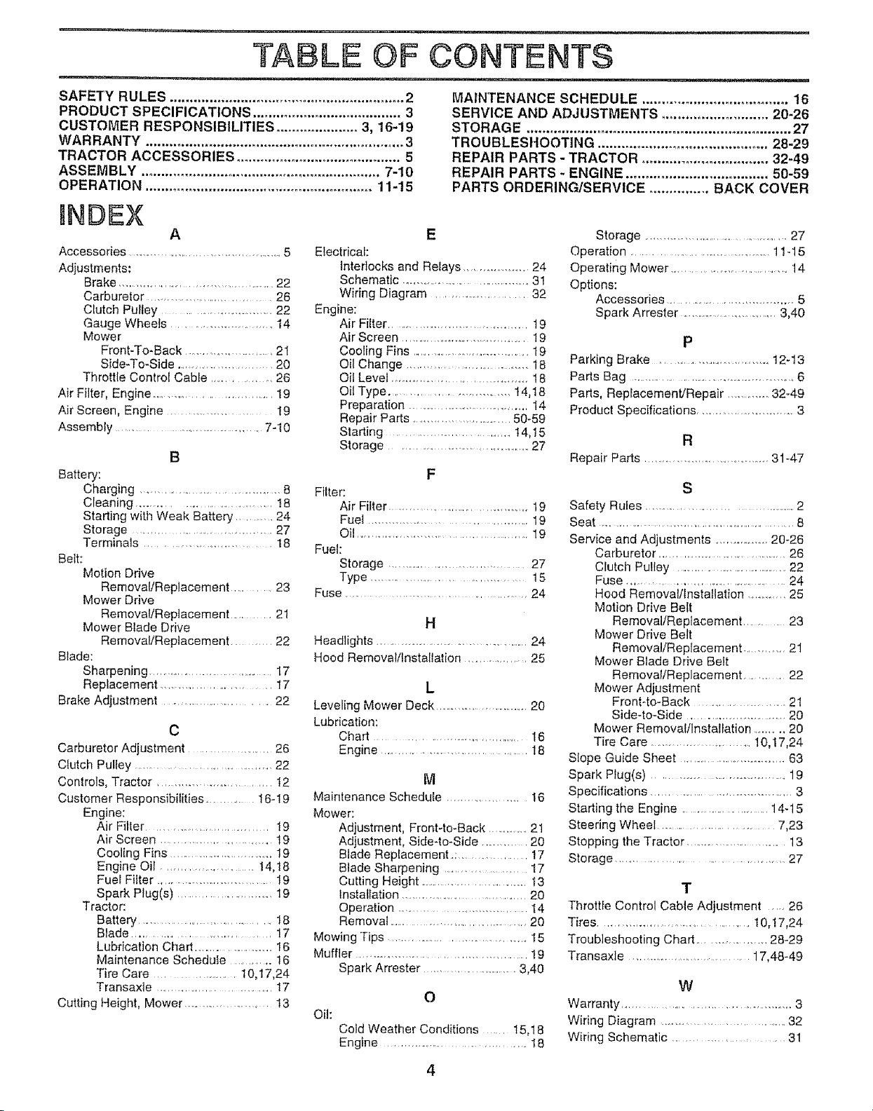
"TABLE OF CONTENTS
SAFETY RULES ............................................................. 2
PRODUCT SPECIFICATIONS ...................................... 3
CUSTOMER RESPONSIBILITIES ..................... 3, 16-19
WARRANTY .................................................................... 3
TRACTOR ACCESSORIES .......................................... 5
ASSEMBLY ............................................................. 7-10
OPERATION .......................................................... 11-15
nNDEX
A
Accessories ........................................... 5
Adjustments:
Brake ...................................................22
Carburetor ............................... 26
Clutch Pulley ............................ 22
Gauge Wheels ......................... t4
Mower
Front-To-Back ..................... 21
Side-To-Side .......................... 20
Throttle Control Cable ................. 26
Air Filter, Engine .............................. t9
Air Screen, Engine ...................... 19
Assembly ................................. 7-10
B
Battery:
Charging ............................................ 8
Cleaning ..................................... !8
Starting with Weak Battery ........... 24
Storage ........................................ 27
Terminals ........................... 18
Belt:
Motion Drive
Removal/Replacement ........ 23
Mower Drive
Removal/Replacement .......... 21
Mower Blade Drive
Removal/Replacement ........... 22
Blade:
Sharpening ............................. 17
Replacement ......................... I7
Brake Adjustment ............................. 22
C
Carburetor Adjustment .................... 26
Ciutch Pulley ................................... 22
Controls, Tractor ........................... 12
Customer Responsibilities ............. t6-19
Engine:
Air Filter ............................... 19
Air Screen ................................ 19
Cooling Fins ................................ 19
Engine Oil ......................... !4,t8
Fuel Filter .............................. 19
Spark Plug(s) ........................ 19
Tractor:
Battery ................................ 18
Blade .............................. 17
Lubrication Chad .............................16
Maintenance Schedute ............. 16
Tire Care ................. 10,17,24
Transaxle ................................. 17
Cutting Height, Mower ........................ t3
Electrical:
Interlocks and Relays ................... 24
Schematic ..................................... 31
Wiring Diagram ....................... 32
Engine:
Air Filter ..................................... 19
Air Screen ........................................ ! 9
Cooling Fins ......................................19
Oil Change .............................. 18
Oil Level ....................................... t 8
Oil Type ........................... 14,18
Preparation ....................................... 14
Repair Parts .............................. 50-59
Starting ................................ 14,t 5
Storage .......................................... 27
Filter:
Air Filter .......................................... 19
Fuel ................................... 19
Oil ................................................ 19
Fuel:
Storage ...................................... 27
Type .................................... 15
Fuse ................................ 24
Headlights ..................................................24
Hood Removal/Installation .............. 25
Leveling Mower Deck ..................................20
Lubrication:
Chart .................................. 16
Engine ...................................... 18
Maintenance Schedule ...................... 16
Mower:
Adjustment, Front4o-Back .................2t
Adjustment, Side4o-Side ........... 20
Blade Replacement.; ..................... 17
Blade Sharpening ..................... 17
Cutting Height .....................................t3
Installation ..................................... 20
Operation ................................ 14
Removal ........................................ 20
Mowing "Tips ..................................... t 5
Muffler ....................................... 19
Spark Arrester ............................. 3,40
Oil:
Cold Weather Conditions .... 15,18
Engine .................................. I 8
MAINTENANCE SCHEDULE ...................................... 16
SERVICE AND ADJUSTMENTS ........................... 20-26
STORAGE ................................................................... 27
TROUBLESltOOTING ............................................ 28-29
REPAIR PARTS - TRACTOR ................................ 32-49
REPAIR PARTS - ENGINE .................................... 50-59
PARTS ORDERING/SERVICE ............... BACK COVER
E
Storage ...............................................27
Operation ............................... 11-15
Operating Mower ................................ 14
Options:
Accessories ....................................... 5
Spark Arrester ............................ 3,40
P
Parking Brake ............................... 12-13
Parts Bag ................................................... 6
Pads, Replacement/Repair ..............32-49
Product Specifications ....................... 3
R
Repair Parts ..................................... 31-47
F
S
Safety Rules ............................................. 2
Seat ............................................................ 8
Service and Adjustments ...................20-26
Carburetor ...........................................26
Clutch Pulley ........................................22
Fuse ................................................. 24
Hood Removal/Installation .......... 25
Motion Drive Belt
M
H
L
Slope Guide Sheet ............................ 63
Spark Plug(s) ....................................... 19
Specifications ......................................... 3
Starting the Engine .................. 14-15
Steering Wheel .......................... 7,23
Stopping the Tractor ..................................13
Storage ........................................ 27
Removal/Replacement ....... 23
Mower Drive Belt
Removal/Replacement ............ 21
Mower Blade Drive Belt
Removal/Replacement ...............22
Mower Adjustment
Front-to-Back ....................... 21
Side-to-Side .............................. 20
Mower Removal/Installation .......... 20
Tire Care ............................. 10,17,24
T
Throttle Control Cable Adjustment .... 26
Tires ....................................... t0,t7,24
Troubleshooting Chart .................... 28-29
Transaxle .................................. 17,48-49
W
O
Warranty ..................................... 3
Wiring Diagram ................................. 32
Wiring Schematic ........................ 31
Page 5
_l,ii ii, H
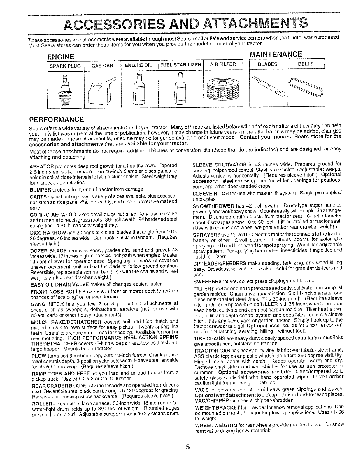
ACCESSORIES AND ATTACHMENTS
......... ii, ........... :
These accessories and attachments were available through most Seers retail outlets and service centers when the tractor was purchased
Most Sears stores can order these items for you when you provide the model number ef your tractor
ENGINE
SPARK PLUG GAS CAN ENGINE OIL
FUEL STABILIZER
AIR FILTER BLADES BELTS |
MAINTENANCE
/
PERFORMANCE
Sears offers a wide variety of attachments that fit your tractor Many of these are listed below with brief explanations of how they can help
you This liet was current at the time of publication; however, it may change in future years - more attachments may be added, changes
may be made in these attachments, or some may no longer be available or fit your model Contact your nearest Sears store for the
accessories and attachments that are available for your tractor°
Most of these attachments do not require additional hitches or conversion kits (those that do are indicated) and are designed for easy
attaching and detaching
AERATOR promotes deep root growth fora healthy lawn. Tapered
2 5-inch steel spikes mounted on lO-inch diameter discs puncture
holes in soil at close intervals to let moisture soak in Sleet weight tray
for increased penetration
BUMPER protects front end of tractor from damage
CARTS make hauling easy Variety of sizes available, plus accesso-
ries such as side panel kits, tool caddy, cart cover, protective mat and
doily,
CORING AERATOR takes smat_ plugs out of soil to allow moisture
and nutrients to reach grass roots 36-inch swath 24 hardened steel
coring tips 150 Ib capacity weight tray
DISC HARROW has 2 gangs of 4 steel blades that angle from 10 to
20 degrees, 40 inches wide Can hook 2 units in tandem. (Requires
sleeve hitch )
DOZER BLADE removes snow; grades dirt, sand arid gravel 48
inches wide, I7 inches high, clears 44-inch path when angled Master
tilt contrel lever for operator ease. Spring trip for snow remevat on
uneven pavement; built-in float for blade to follow ground contour,
Reversible, replaceable scraper bar (Use with tire chains and wheel
weights and/or rear drawbar weight)
EASY OIL DRAIN VALVE makes oil changes easier, faster
FRONT NOSE ROLLER canters in front of mower deck to reduce
chances of "scalping" on uneven terrain
GANG HITCH tets you tow 2 or 3 putt-behind attachments at
once, such as sweepers, dethatchers, aerators (not for use with
rollers, carts or other heavy attachments).
MULCH RAKE/DETHATCHER loosens soil and flips thatch and
matted leaves to lawn surface for easy pickup Twenty spring tine
teeth Usefut to prepare bare areas for seeding. Available for front or
rear mounting. HIGH PERFORMANCE REEL*ACTION SPRING
TINE DETHATCHER covers 36qnch wide path and tosses thatch into
_arge hopper Mounts behind tractor
PLOW turns soil 6 inches deep, cuts tO-inch furrow Crank adjust-
ment controls depth, 3-position yoke sets width Heavy steel landside
for straight furrowing (Requires sieeve hitch)
RAMP TOPS AND FEET let yeu lead and unload tractor from a
pickup truck Use wifh 2 x 8 or 2 x t0 lumber
REAR GRADER BLADE is 42 incheswide and operated from driver's
seat Reversible steel blade can be angled at 30 degrees for grading
Reverses for pushing snow backwards (Requires sleeve hitch )
ROLLER for smoother lawn surface. 36-inch wide, 18-inch diameter
water-tight drum holds up to 390 [bs of weighL Rounded edges
prevent harm to turf Adjustable scraper automatically cleans drum.
SLEEVE CULTIVATOR is 43 inches wide. Prepares ground for
seeding, helps weed control Steel frame holds 5 adiustable sweeps.
Adjusts vertically, horizontally (Requires sleeve hitch) Optional
accessory: steel furrow opener for wider openings for potatoes,
cem, and ether deep-seeded crops
SLEEVE HITCH for use with master lift system Single pin couples/
uncouples.
SNOWTHROWER has 42-inch swath Drum-type auger handles
powdery and web'heavy snow Mounts easily with simple pin arrange-
ment. Discharge chute adjusts from tractor seat 6-inch diameter
spout discharges snow 10 to 50 feet Lift centrolfed at tractor seat.
(Use with chains and wheel weights and/or rear drawbar weight.)
SPRAYERS use 12-volt DC efectric motor that connecls te the tractor
battery or other 12-vo_t source Includes booms for automatic
spraying and hand held wand for spot spraying Wand has adjustable
spray pattern, For appIying herbicides, insecticides, fungicides and
liquid fertilizers
SPREADERtSEEDERS make seeding, fertilizing, and weed killing
easy Broadcast spreaders are also useful for granular de-icers and
sand
SWEEPERS let you coIlect grass clippings and leaves
TILLER has 8 hp engine to prepare seed beds, cultivate, and compost
garden residue Chain-drive transmission Six 11-inch diameterone
piece heat-treated steel tines, Tills 30-inch path (Requires sleeve
hitch ) Or use 5 hp tow-behind TILLER with 36-inch swath to prepare
seed beds, cultivate and compost garden residue Tiller has its own
built-in lift and depth control system and does NOT require a sleeve
hitch Fits any lawn, yard or garden tractor Simply hook up to the
tractor drawbar and gel Optional accessories for 5 hp tiller convert
unit for dethatching, aerating, hilling without tools
TIRE CHAINS are heavy duty; closely spaced extra-large cross links
give smooth ride, outstanding traction
TRACTOR CAB has heavy duty vinyl fabric over tubular steel frame,
ABS plastic top; clear ptastic windshield offers 360 degree visibility
Hinged metal doors with catch, Keeps operator warm and dry
Remove vinyl sides and windshields for use as sun protector in
summer, Optional accessories include: tinted/tempered solid
safety glass windshield with hand operated wiper; 12-vott amber
caution light for mounting on cab top
VACS for powerful collection of heavy grass clippings and leaves
Optional wand attachment te pick up debris in hard*to-reach places
VAC/CHIPPER includes a chipper-shredder,
WEIGHT BRACKET for drawbar for snow removal appfications, Can
be mounted on front of tractor for plowing applications Uses (1) 55
Ib weight
WHEEL WEIGHTS for rear wheels provide needed traction for snow
removal or dozing heavy materials
Page 6
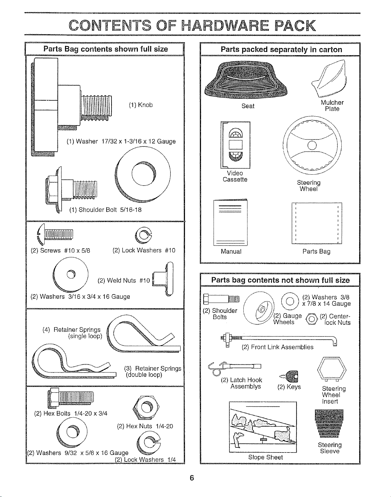
CONTENTS OF HARDWARE: PACK
,,,1_............... ,...............
Parts Bag contents shown full size
Parts packed separately in carton
(1) Washer t7/32 x 1-3/16 x 12 Gauge
(t) Shoulder Bolt 5/16-18
(2) Screws #10 x 5/8
(S,
(2) Washers 3/16 x 3/4 x 16 Gauge
(2) Lock Washers #10
(2) Weld Nuts #10 _ I
(1) Knob
=Li
Seat Plate
Mulcher
r-q
Video
Cassette
Manual
Parts bag contents not shown full size
f'-'-_"_ (/_X (2)Washers 3/8
Steering
Wheel
i
Parts Bag
(4) Retainer Springs
(single loop)
1
(3) Retainer Springs
(double loop)
(2) Hex Bolts 1/4-20 x 3/4 "_'k,.._-"_/
(2) Hex Nuts 1/4-20
(2) Washers 9/32 x 5/8 x 16 Gauge '_
(2) Lock Washers 1/4
(2) Shoulder
Bolts
_:!_(2) Front Link Assemblies
(2) Latch Hook
Assemblys (2) Keys
Li/y(2) Gauge z'_ (2) Center-
\.__:S / Wheels _ lock Nuts
Slope Sheet
Steering
Wheel
Insert
Steering
Sleeve
Page 7
...... i i .... iiii¸ i, t n ,',1 n Iiu ii ,,i ...... w:-:-L ,Ji,,,,,,,11 i,, !
ASSEMBLY
n i i i i...................... ...... in i, I ,,i,n ,L , i ..............
Your new tractor has been assembled at the factory with the exception of those parts left unassembled for shipping purposes_
To ensure safe and proper operation of your tractor all parts and hardware you assemble must be tightened securely,, Use
the correct too]s as necessary to insure proper tightness
TOOLS REQUIRED FOR ASSEMBLY
A socket wrench set will make assembly easier° Standard
wrench sizes are listed,
(2) 7/16" wrenches Tire pressure gauge
(1) 1/2" wrench Utility knife
(1) 9/16" wrench
(1) 3/4" socket with drive ratchet
When right or left hand is mentioned in this manual, it
means when you are in the operating position (seated
behind the steering wheel)
TO REMOVE TRACTOR FROM CARTON
UNPACK CARTON
• Remove all accessible loose parts and parts cartons
from carton (See page 6).
. Cut, from top to bottom, along lines on all four corners
of carton, and lay panels flat
• Remove mower and packing matedals
o Check for any additional loose parts or cartons and
remove_
BEFORE ROLLING TRACTOR OFF SKID
i
ADAPTER t_i_L_! //
/ t / /
t t i/ 1
STEERING
WHEEL
// / STEERING
,_. _],/" /" SLEEVE .
I
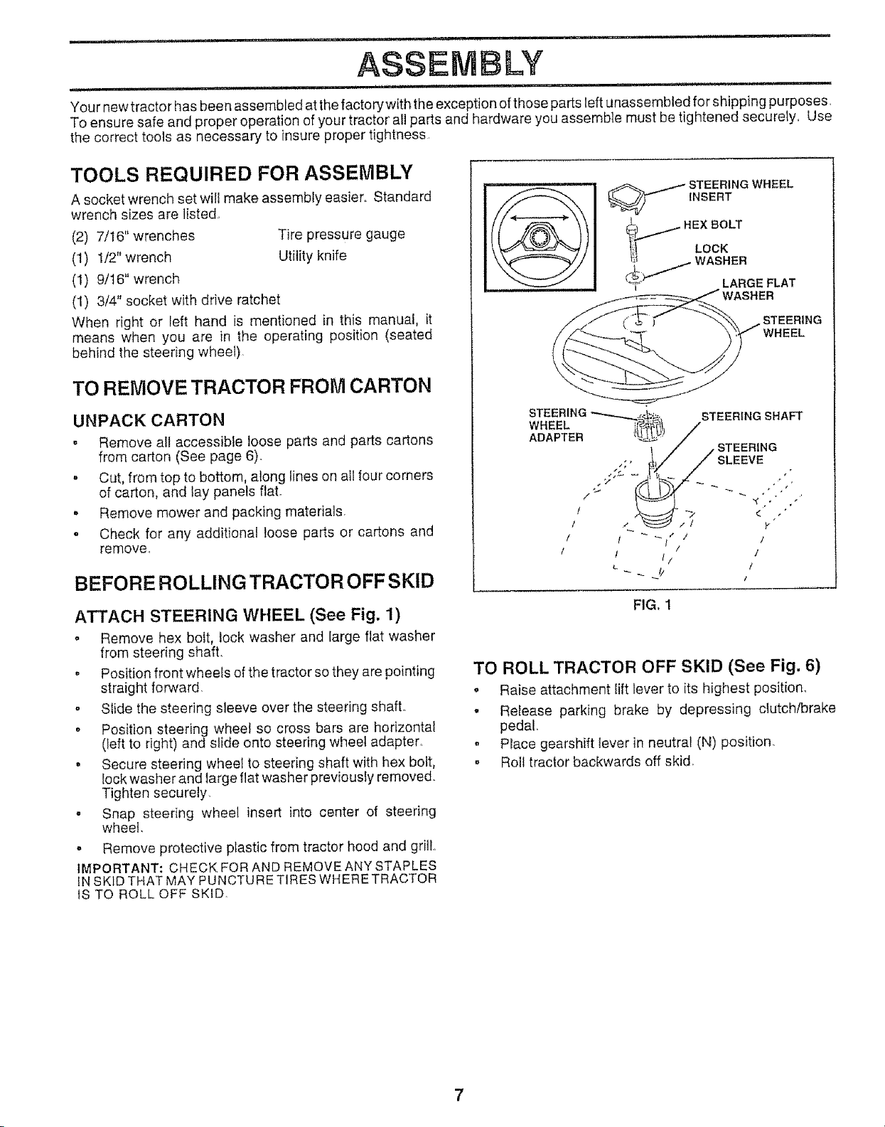
ATTACH STEERING WHEEL (See Fig. 1)
o Remove hex boit, lock washer and large flat washer
from steering shafL
• Position front wheels of the tractor so they are pointing
straight forward.
. Slide the steering sleeve over the steering shaft
o Position steering wheel so cross bars are horizontal
(left to right) and slide onto steering wheel adapter,
° Secure steering wheel to steering shaft with hex bolt,
lock washer and large flat washer previously removed.
Tighten securely,
o Snap steering wheel insert into center of steering
wheel.
. Remove protective plastic from tractor hood and grill,,
IMPORTANT: CHECK FOR AND REMOVE ANY STAPLES
iN SKID THAT MAY PUNCTURE TIRES WHERE TRACTOR
IS TO ROLL OFF SKID
FIG. I
TO ROLL TRACTOR OFF SKID (See Fig. 6)
. Raise attachment lift lever to its highest position_
- Release parking brake by depressing clutch/brake
pedal.
. Place gearshift lever in neutral (N) position.
- Roll tractor backwards off skid
7
Page 8
,,, = ........................................
ASSEMBLY
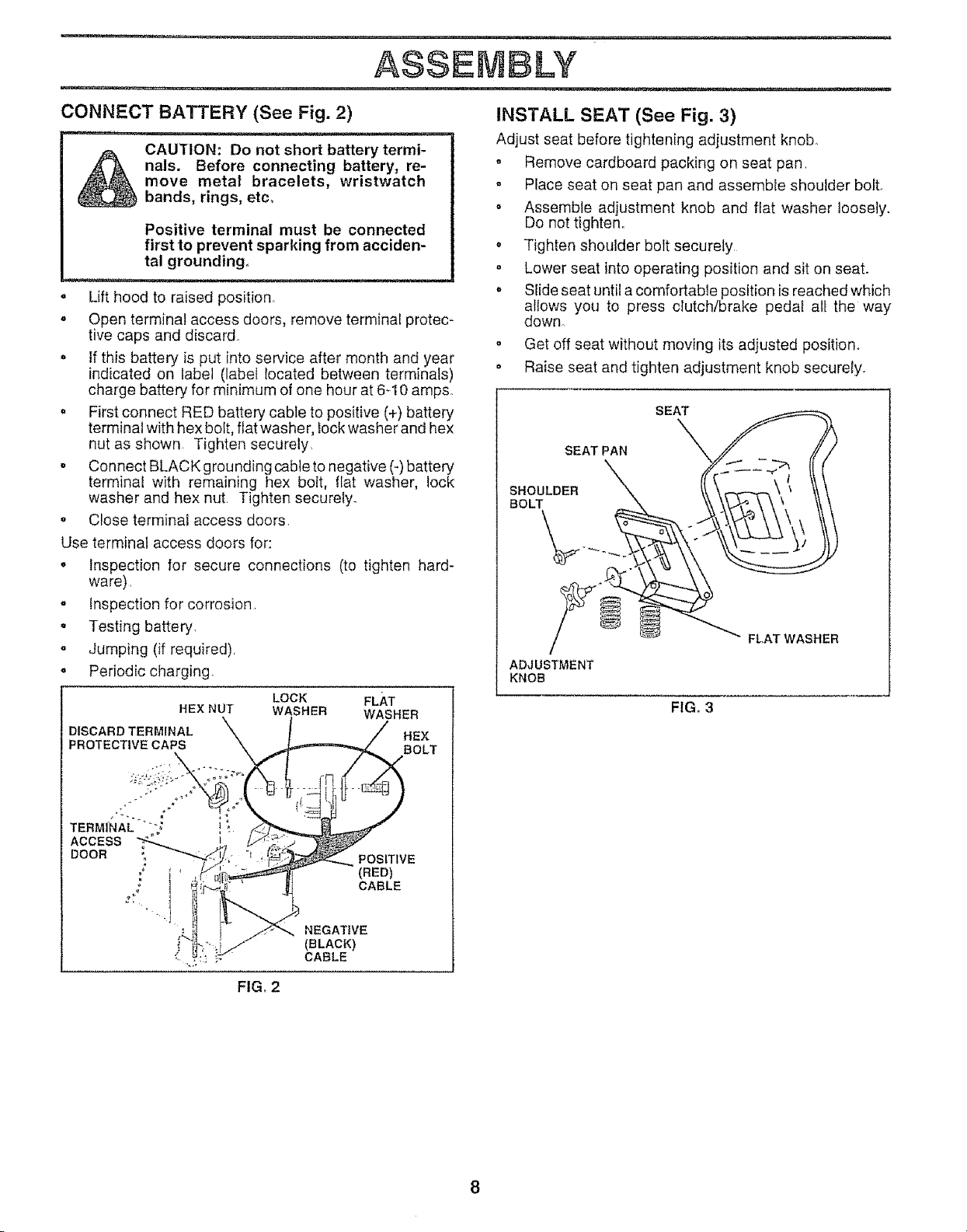
CONNECT BATTERY (See Fig. 2)
nals. Before connecting battery, re-
_ CAUTION: Do not short battery termi-
o Lift hood to raised position.
• Open terminal access doors, remove terminal protec-
tive caps and discard.
• If this battery is put into service after month and year
indicated on label (label located between terminals)
charge battery for minimum of one hour at 6-10 ampso
= First connect RED battery cable to positive (+) battery
terminal with hex bolt, flat washe r, lock washer and hex
nut as shown Tighten securely,
o Connect BLACK grounding cable to negative (-) battery
terminal with remaining hex bott, flat washer, lock
washer and hex nut, Tighten securely_
o Close terminat access doors
Use terminal access doors for:
o Inspection for secure connections (to tighten hard-
ware),
o Inspection for corrosion
• Testing battery,
o Jumping (if required),
. Periodic charging.
DISCARD TERMINAL X . . / HE×
move metal bracelets, wristwatch
bands, rings, etc,
Positive terminal must be connected
first to prevent sparking from acciden-
tal grounding,
LOCK FLAT
HEX NUT WASHER WASHER
INSTALL SEAT (See Fig. 3)
Adjust seat before tightening adjustment knob
o Remove cardboard packing on seat pan
• Place seat on seat pan and assemble shoulder bolt.
• Assemble adjustment knob and flat washer loosely.
Do not tighten.
o Tighten shoulder bolt securely
o Lower seat into operating position and sit on seat.
o Slide seat until a comfortable position is reached which
allows you to press clutch/brake pedal all the way
down°
o Get off seat without moving its adjusted position.
. Raise seat and tighten adjustment knob securely.
SEAT
SEAT PAN
SHOULDER _'X
ADJUSTMENT
KNOB
X
FIG. 3
TERMINA_.....i ;
AccEss_ ii i_t;_
DOOR _ _.i:, -i_
j* BLACK)
FIG, 2
(BED)
CABLE
Page 9
ASSEMBLY
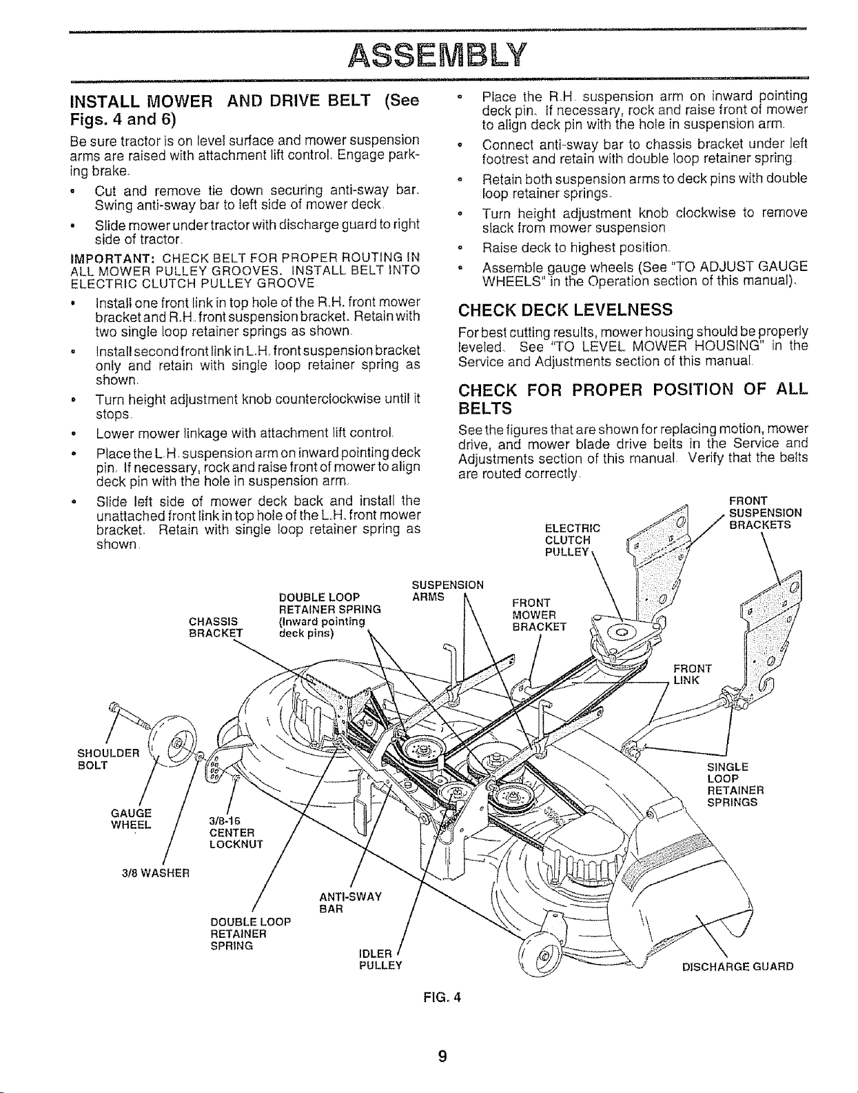
INSTALL MOWER AND DRIVE BELT (See
Figs. 4 and 6)
Be sure tractor is on level surface and mower suspension
arms are raised with attachment lift control Engage park-
ing brake.
. Cut and remove tie down securing anti-sway bar.
Swing antFsway bar to left side of mower deck
• Slide mower under tractor with discharge guard to right
side of tractor.
IMPORTANT: CHECK BELT FOR PROPER ROUTING IN
ALL MOWER PULLEY GROOVES. INSTALL BELT INTO
ELECTRIC CLUTCH PULLEY GROOVE
• Install one front link in top hole of the R,H, front mower
bracket and R°H, front suspension bracket. Retain with
two single loop retainer springs as shown.
o install second front link in L.H,,front suspension bracket
only and retain with single loop retainer spring as
shown,
• Turn height adjustment knob counterclockwise until it
stops,
o Lower mower linkage with attachment lift control,
, Place the L,H, suspension arm on inward pointing deck
pin, If necessary, rock and raise front of mower to align
deck pin with the hole in suspension arm,
. Slide left side of mower deck back and install the
unattached front link in top hole of the L,,Hofront mower
brackeL Retain with single loop retainer spring as
shown,
o Place the R.H, suspension arm on inward pointing
deck pin. If necessary, rock and raise front of mower
to align deck pin with the hole in suspension arm.
o Connect anti-sway bar to chassis bracket under left
footrest and retain with double loop retainer spring
o Retain both suspension arms to deck pins with double
loop retainer springs,
o Turn height adjustment knob clockwise to remove
slack from mower suspension
o Raise deck to highest position.
o Assemble gauge wheels (See TO ADJUST =AUGE
WHEELS" in the Operation section of this manual),
CHECK DECK LEVELNESS
For best cutting results, mower housing should be properly
leveled. See '%0 LEVEL MOWER HOUSING" in tile
Service and Adjustments section of this manual
CHECK FOR PROPER POSITION OF ALL
BELTS
See the figures that are shown for replacing motion, mower
drive, and mower blade drive belts in the Service and
Adjustments section of this manual. Verify that the belts
are routed correctly.
FRONT
SUSPENSION
ELECTRIC
CLUTCH
PULLEY
BRACKETS
SHOULDER
BOLT
GAUGE
WHEEL
/
3t8 WASHER
DOUBLE LOOP
CHASSIS (Inward pointing
BRACKET deck pins)
3/8-16
CENTER
LOCKNUT
DOUBLE LOOP
RETAINER
SPRING
RETAINER SPRING
/
ANTI-SWAY
BAR
IDLER
PULLEY
SUSPENSION
ARMS
FRONT
MOWER
BRACKET
FRONT
LINK
SINGLE
LOOP
RETAINER
SPRINGS
\\
DISCHARGEGUARD
FIG. 4
Page 10
ASSEI BLY
............. _ , ...... , ........... i,, i........... i, , i ......
CHECK TiRE PRESSURE
The tires on your tractor were overinfiated at the factory for
shipping purposes Correct tire pressure is important for
best cutting performance.
° Reduce tire pressure to PSI shown in "PRODUCT
SPECIFICATIONS" on page 3 of this manual.
CHECK BRAKE SYSTEM
After you tearn how to operate your tractor, check to see
that the brake is properly adjusted_ See "TO ADJUST
BRAKE" in the Service and Adjustments section of this
manua!.
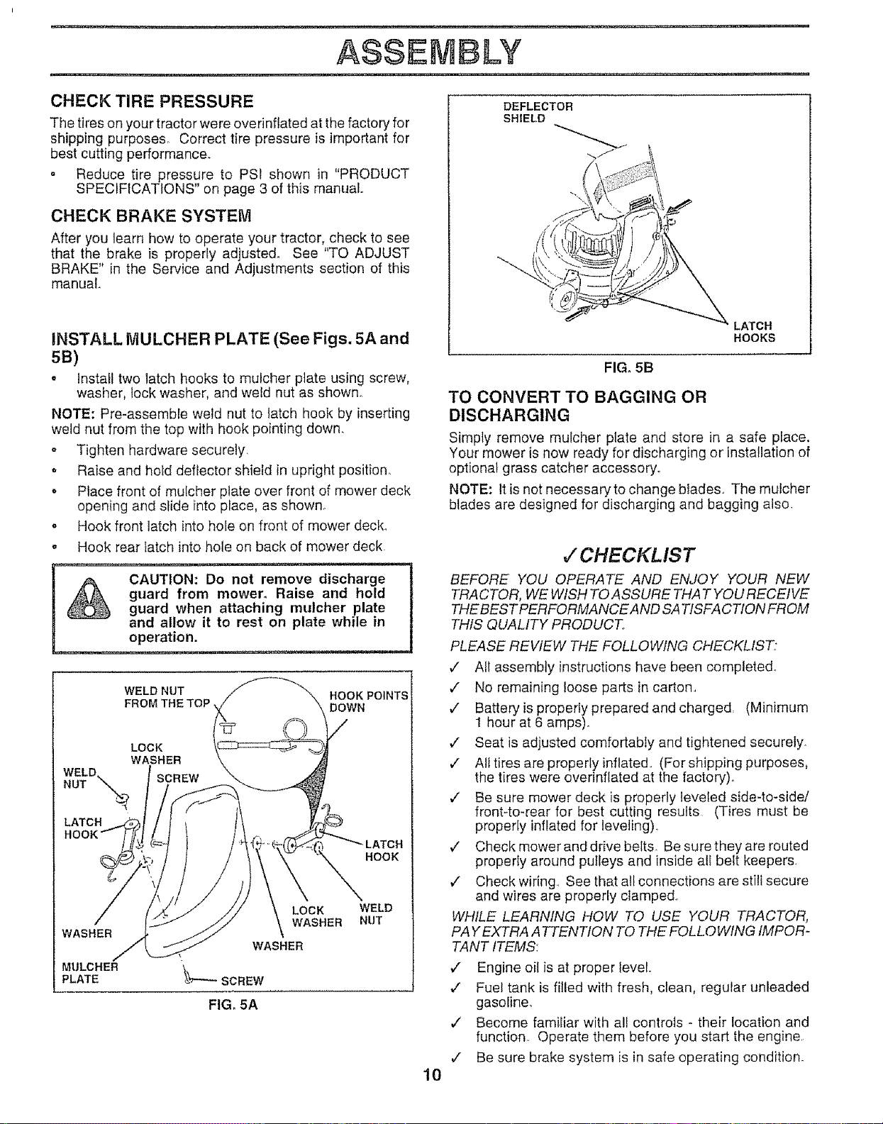
INSTALL MULCHER PLATE (See Figs. 5A and
SB)
o install two latch hooks to mulcher ptate using screw,
washer, lock washer, and weld nut as shown°
NOTE: Pre-assemble weld nut to latch hook by inserting
weld nut from the top with hook pointing down.
o Tighten hardware securely,
o Raise and hold deflector shield in upright position..
o Place front of mulcher plate over front of mower deck
opening and slide into place, as shown_
o Hook front latch into hole on front of mower deck_
o Hook rear latch into hole on back of mower deck.
_, CAUTION:Do not remove discharge
,_ guard from mower. Raise and hold
_ guard when attaching mulcher plate 1
WELD. SCREW
NUT \-\
LATCH
WASHER
MULCHER
PLATE
and allow it to rest on plate while in
operation. I
WELD NUT HOOK POINTS
FROM THE TOP DOWN
LOCK
WASHER
HOOK
LOCK
WASHER
WASHER
WELD
NUT
_---SCREW
FIG, 5A
LATCH
HOOKS
FIG. 5B
TO CONVERT TO BAGGING OR
DISCHARGING
Simply remove mulcher plate and store in a safe place.
Your mower is now ready for discharging or installation of
optional grass catcher accessory_
NOTE: It is not necessaryto change blades.. The mulcher
blades are designed for discharging and bagging also.
CHECKL IST
BEFORE YOU OPERATE AND ENJOY YOUR NEW
TRACTOR, WE WISH TO ASSURE THAT YOU RECEIVE
THE BEST PERFORMANCE AND SA TISFA CTION FROM
THIS QUALITY PRODUCT.
PLEASE REVIEW THE FOLLOWING CHECKLIST"
•/ All assembly instructions have been completed.
v" No remaining loose parts in carton.
¢ Batteryis properly prepared and charged (Minimum
1 hour at 6 amps).
¢ Seat is adjusted comfortably and tightened securely_
¢ All tires are properly inflated.. (For shipping purposes,
the tires were everinflated at the factory),
¢" Be sure mower deck is properly leveled side-to-side/
front-to-rear for best cutting results (Tires must be
properly inflated for leveling):
¢" Check mower and drive belts. Be sure they are routed
properly around putleys and inside all belt keepers.
€" Check wiring.. See that all connections are still secure
and wires are properly clamped.
WHILE LEARNING HOW TO USE YOUR TRACTOR,
PA YEXTRA ATTENTION TO THE FOL L0 WING IMPOR-
TANT ITEMS:
v" Engine oil is at proper level.
v" Fuel tank is filled with fresh, clean, regular unleaded
gasoline,
,/ Become familiar with all controls - their location and
function. Operate them before you start the engine.
¢ Be sure brake system is in safe operating condition.
10
Page 11
, u ,, ,n iii, ii, i i i i ,i ii,,
OPERATUON
ii ,lU ,,,lu ii i,i ,i
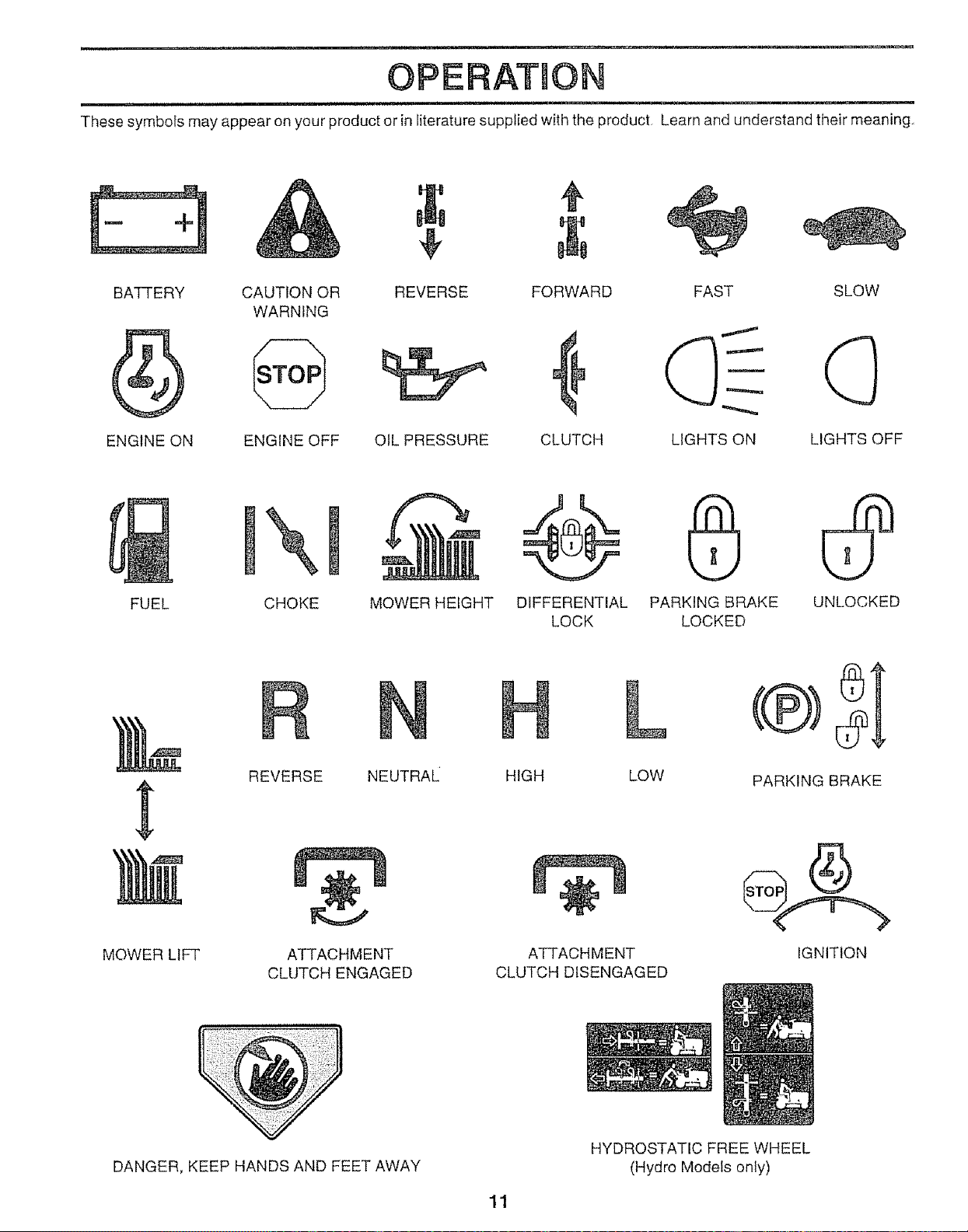
These symbols may appear on your product or in literature supplied with the product Learn and understand their meaning,
÷
BATTERY
ENGINE ON ENGINE OFF LIGHTS OFF
CAUTION OR SLOW
WARNING
REVERSE FORWARD FAST
OIL PRESSURE CLUTCH LIGHTS ON
\
FUEL
CHOKE MOWER HEIGHT DIFFERENTIAL PARKING BRAKE UNLOCKED
LOCK LOCKED
}4
REVERSE NEUTRAL
MOWER LIFT
DANGER, KEEP HANDS AND FEET AWAY
ATTACHMENT
CLUTCH ENGAGED
HIGH LOW
ATTACHMENT
CLUTCH DISENGAGED
HYDROSTATIC FREE WHEEL
(Hydro Models only)
11
PARKING BRAKE
IGNITION
Page 12

OPERATNON
........... i lu-,,,.i,r ¸
KNOW YOUR TRACTOR
READ THIS OWNER'S MANUAL AND SAFETY RULES BEFORE OPERATING YOUR TRACTOR
Comparetheiilustrationswithyourtractortofamiliarizeyourselfwiththe locations ofvarious controls and adjustments,, Save
this manual for future reference,,
AMMETER
CHOKECONTROL
LIGHT SWITCH
CLUTCH/BRAKE
PEDAL
THROTTLE
CONTROL
ATTACHMENT CLUTCH SWITCH
IGNITION SWITCH
LIFT LEVER
PLUNGER
J
LtFT LEVER
PARKING BRAKE
LEVER
HEIGHT
ADJUSTMENT
KNOB
GEARSHIFT LEVER
Our tractors conform to the safety standards of the American National Standards Institute
ATTACHMENT CLUTCH SWITCH- Used to engage mower
blades or other attachments mounted to your tractor.
LIFT LEVER _ Used to raise and lower mower deck or othe r
attachments mounted to your tractor°
LIFT LEVER PLUNGER - Used to release attachement lift
lever when changing its position_
CLUTCH/BRAKE PEDAL - Used for declutching and
braking the tractor and starting the engine,
GEARSHIFT LEVER - Selects the speed and direction of
tractor.
THROTTLE CONTROL - Used to control engine speed.
RANGESHtFT
LEVER
FIGo6
RANGE SHIFT LEVER - Allows high (H) or low (L) speed
for atl forward and reverse gears,
IGNITION SWITCH - Used to start and stop the engine
AMMETER - Indicates battery charging (+) or discharging
(-),
LIGHT SWITCH -Turns the headlights on and off
PARKING BRAKE LEVER - Locks clutch/brake pedal into
the brake position,,
CHOKE CONTROL - Used when starting a cold engine,,
HEIGHT ADJUSTMENT KNOB -Used to adjust the mower
height.
12
Page 13
OPERATION
.-- , n,,n i1, ,i ,,
_ The operation of any tractor can result in foreign objects thrown into the eyes, which can
result in severe eye damage, Always wear safety glasses or eye shields while operating
your tractor or performing any adjustments or repairs. We recommend a wide vision safety
mask over the spectacles or standard safety glasses,
HOW TO USE YOUR TRACTOR
..... n ,i i, .... i , ii,li,_
.............................................. ,,u ,,i i,un,,,
NOTE: Under certain conditions when tractor is standing
idle with the engine running, hot engine exhaust gases may
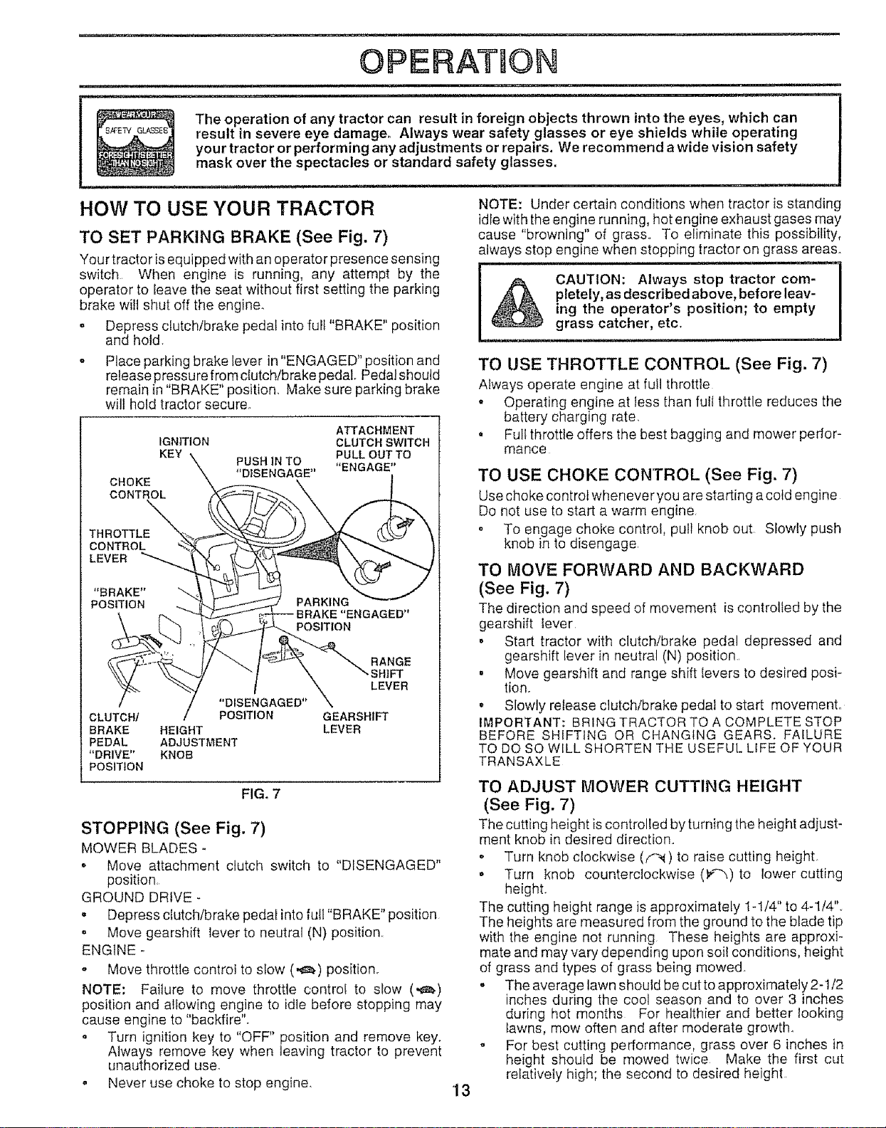
TO SET PARKING BRAKE (See Fig. 7)
Your tractor is equipped with an operator presence sensing
cause "browning" of grass., To eliminate this possibility,
always stop engine when stopping tractor on grass areas.,
, ,, ,n ,, H ,i i, i, ,,
switch When engine is running, any attempt by the
operator to leave the seat without first setting the parking
brake witt shut off the engine,
. Depress clutch/brake pedal into full "BRAKE" position
pletely, as described above, before leav-
CAUTION: Always stop tractor com-
ing the operator's position; to empty
grass catcher, etc.
and hold
Place parking brake lever in "ENGAGED" position and
release pressure from clutch/brake pedal Pedalshoutd
remain in "BRAKE" position, Make sure parking brake
will hold tractor secure_
TO USE THROTTLE CONTROL (See Fig. 7)
Always operate engine at futl throttle
- Operating engine at less than full throttle reduces the
battery charging rate,
CHOKE
CONTROL
IGNITION CLUTCH SWlTCH
KEY PULLOUTTO
PUSHINTO "ENGAGE"
"DISENGAGE"
ATTACHMENT
• Full throttle offers the best bagging and mower perfor-
mance
TO USE CHOKE CONTROL (See Fig. 7)
Use choke control whenever you are starting a cold engine
Do not use to start a warm engine
THROTTLE
CONTROL
LEVER
. To engage choke control, pull knob out Slowly push
knob in to disengage
TO MOVE FORWARD AND BACKWARD
(See Fig. 7)
The direction and speed of movement is controlled by the
gearshift Iever
, Start tractor with clutch/brake pedal depressed and
RANGE
"SHIFT
LEVER
"DISENGAGED"
CLUTCH/ POSITION GEARSHIFT
BRAKE HEIGHT LEVER
PEDAL ADJUSTMENT
"DRIVE" KNOB
POSITION
FIG_ 7
gearshift lever in neutral (N) position.
. Move gearshift and range shift levers to desired posi-
tion.
. Slowly release clutch/brake pedal to start movement,
IMPORTANT: BRING TRACTOR TO A COMPLETE STOP
BEFORE SHIFTING OR CHANGING GEARS. FAILURE
TO DO SO WILL SHORTEN "],'HEUSEFUL LIFE OF YOUR
TRANSAXLE
TO ADJUST MOWER CUTTING HEIGHT
(See Fig. 7)
STOPPING (See Fig. 7)
MOWER BLADES -
. Move attachment clutch switch to "DISENGAGED"
position,
GROUND DRIVE -
• Depress clutch/brake pedal into futl "BRAKE" position
= Move gearshift !ever to neutral (N) position,,
ENGINE -
. Move throttle control to slow (,_) position,
NOTE: Failure to move throttle control to slow (._)
position and a!lowing engine to idle before stopping may
cause engine to "backfire".
= Turn ignition key to "OFF" position and remove key.
Always remove key when leaving tractor to prevent
unauthorized use°
o Never use choke to stop engine.
The cutting height is controlled by turning the height adjust-
merit knob in desired direction.
o Turn knob clockwise (f_) to raise cutting height
• Turn knob counterclockwise (_'_"_)to lower cutting
height.
The cutting height range is approximately 1-1/4" to 4-1/4".,
The heights are measured from the ground to the blade tip
with the engine not running These heights are approxi-
mate and may vary depending upon soil conditions, height
of grass and types of grass being mowed.
• The average lawn should be cut to approximately 2-1f2
inches during the cool season and to over 3 inches
during hot months For healthier and better looking
lawns, mow often and after moderate growth.
° For best cutting performance, grass over 6 inches in
height should be rnowed twice Make the first cut
relatively high; the second to desired height
13
Page 14
OPERATm©N
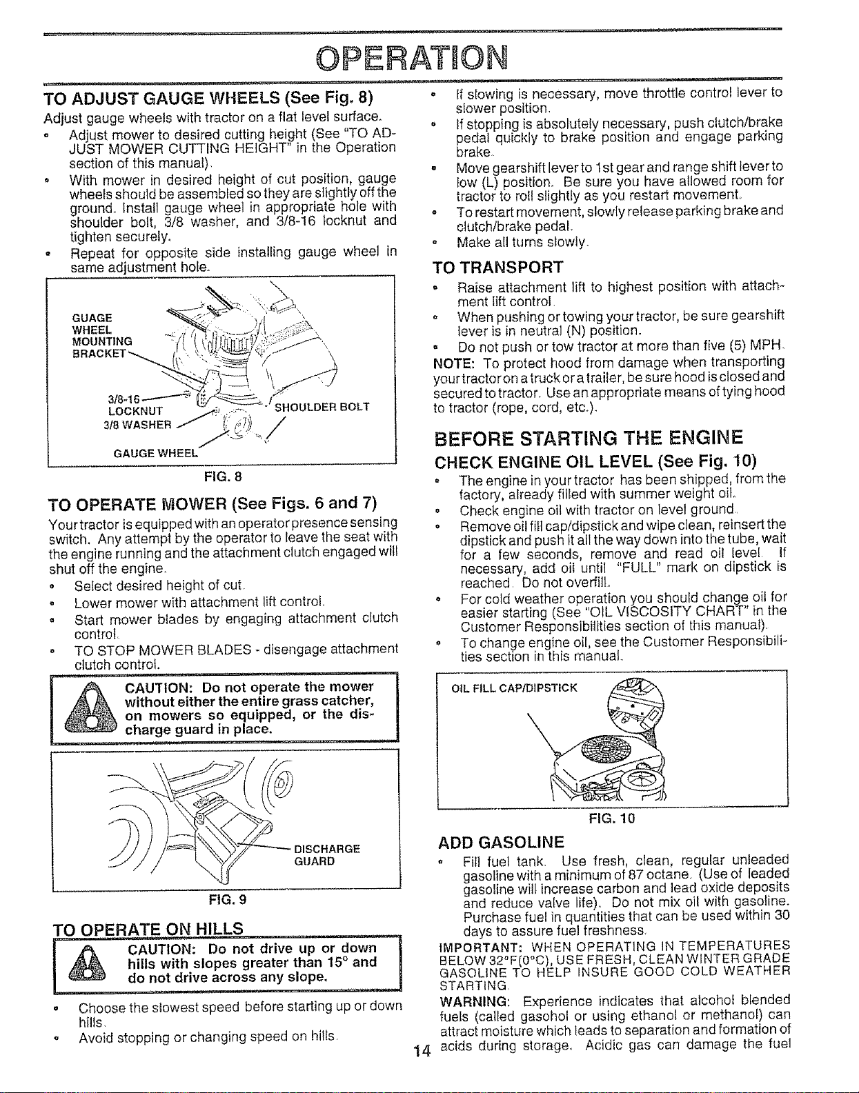
TO ADJUST GAUGE WHEELS (See Fig. 8) °
Adjust gauge wheels with tractor on a flat level surface.
• Adjust mower to desired cutting height (See "TO AD-
JUST MOWER CUTTING HEIGHT" in the Operation
section of this manual).
o With mower in desired height of cut position, gauge
wheels should be assembled so they are slightly off the
ground. Install gauge wheel in appropriate hole with
shoulder bolt, 3/8 washer, and 3f8-16 tocknut and
tighten securely,.
o Repeat for opposite side installing gauge wheel in
same adjustment hole.
GUAGE
WHEEL _._
MOUNTING "
\.
3/8-16 ,-L' '_D ER BOLT
LOCKNUT " ._-
318WASHER J_' /
GAUGE WHEEL
FIG. 8
TO OPERATE MOWER (See Figs. 6 and 7)
Your tractor isequipped with an operator presence sensing
switch. Any attempt by the operator to leave the seat with
the engine running and the attachment clutch engaged will
shut off the engine.
• Select desired height of cut
o Lower mower with attachment lift control..
o Start mower blades by engaging attachment clutch
controt_
o TO STOP MOWER BLADES - disengage attachment
clutch control,
CAUTION: Do'n0i opera;'e"'the mower I
_ without either the entire grass catcher,
on mowers so equipped, or the dis- |
________ charge guard in place.:..............
,,,i ..........
If slowing is necessary, move throttle control lever to
slower position.
, If stopping is absolutely necessary push clutch/brake
pedal quickly to brake position and engage park ng
brake.
. Move gearshift lever to 1st gear and range shift tever to
low (L) position. Be sure you have allowed room for
tractor to roll slightly as you restart movement,.
o To restart movement, slowly release parking brake and
clutchlbrake pedal.
o Make all turns slowly.
TO TRANSPORT
o Raise attachment lift to highest position with attach-
ment lift control
o When pushing or towing your tractor, be sure gearshift
lever is in neutral (N) position.
Do not push or tow tractor at more than five (5) MPH
NOTE: To protect hood from damage when transporting
your tractor on atruck or atrailer, be sure hood is closed and
secured totractor.. Use an appropriate means of tying hood
to tractor (rope, cord, etc.).
BEFORE STARTING THE ENGINE
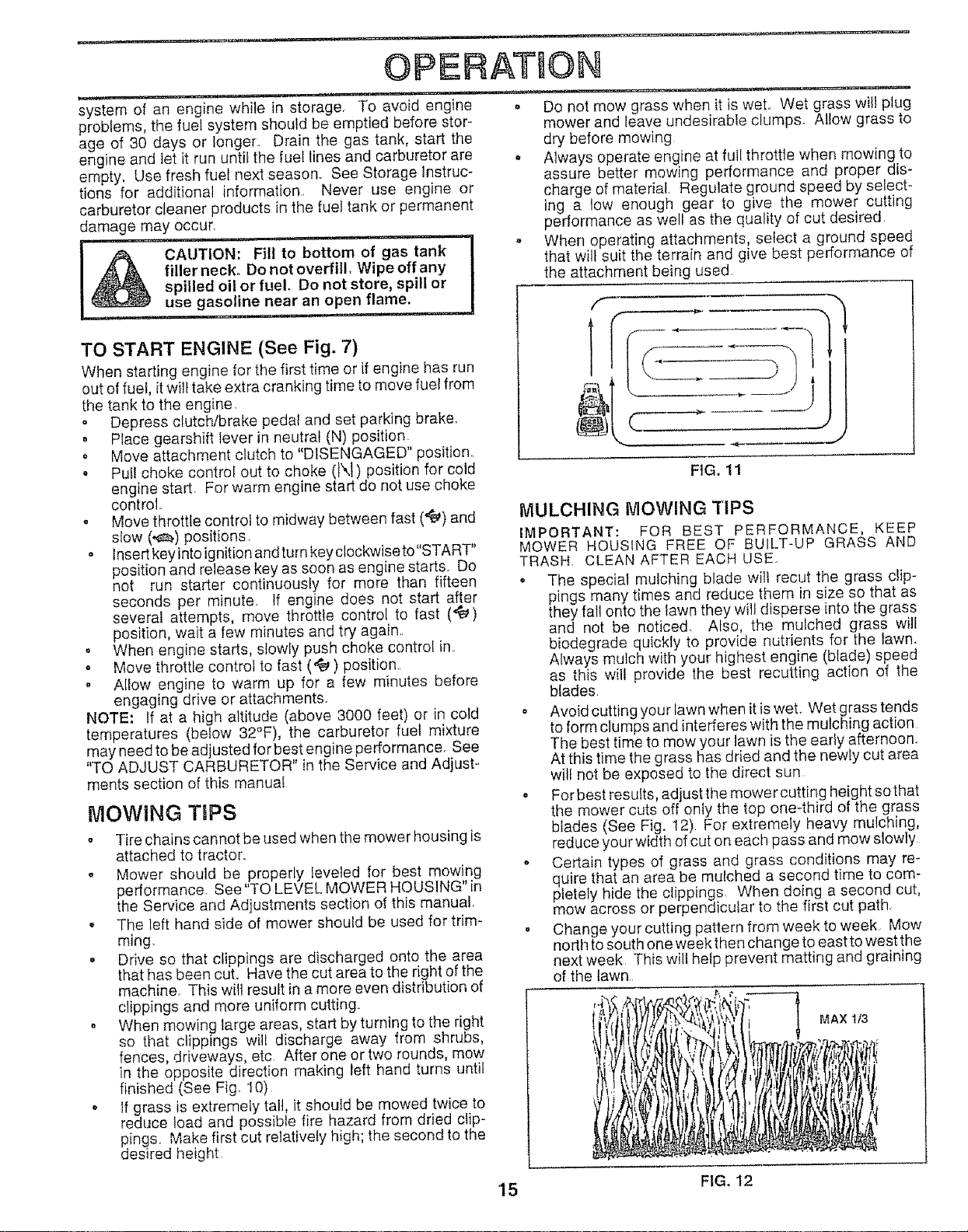
CHECK ENGINE OIL LEVEL (See Fig. 10)
o The engine in your tractor has been shipped, from the
factory, already filled with summer weight oil.
o Check engine oil with tractor on level ground
° Remove oil fill cap/dipstick and wipe clean, reinsert the
dipstick and push it allthe way down into the tube, wait
for a few seconds, remove and read oil level If
necessary, add oil until "FULL" mark on dipstick is
reached Do not overfill.
o For cold weather operation you should change oil for
easier starting (See "OIL VISCOSITY CHART" in the
Customer Responsibilities section of this manual).
o To change engine oil, see the Customer Responsibili-
ties section in this manual
OIL FILL CAP/DIPSTICK
;HARGE
GUARD
FIG. 9
TO OPERATE ON HILLS
4_ .....CAIJ'TION:'Do not drive 'u';'0'r down ]
hills with slopes greater than 15° and II
i
°
Choose the slowest speed before starting up or down
hills.
Avoid stopping or changing speed on hills.
do not drive across any slope. !
FIG. 10
ADD GASOLINE
o Fill fuel tank_ Use fresh, clean, regular unleaded
gasoline with a minimum of 87 octane. (Use of leaded
gasoline wilt increase carbon and lead oxide deposits
and reduce valve life)o Do not mix oil with gasoline.
Purchase fuel in quantities that can be used within 30
days to assure fuel freshness
IMPORTANT: WHEN OPERATING IN TEMPERATURES
BELOW 32°F(0°C), USE FRESH, CLEAN WINTER GRADE
GASOLINE TO HELP INSURE GOOD COLD WEATHER
STARTING.
WARNING: Experience indicates that alcohol blended
fuets (called gasohol or using ethanol or methanol) can
attract moisture which leads to separation and formation of
14 acids during storage.. Acidic gas can damage the fuel
Page 15
OPERATION
system of an engine while in storage. To avoid engine o Do not mow grass when it is wet,, Wet grass will plug
problems, the fuef system should be emptied before stor- mower and leave undesirable clumps Allow grass to
age of 30 days or longer. Drain the gas tank, start the
engine and let it run until the fuel lines and carburetor are
empty. Llse fresh fuel next season,, See Storage Instruc-
tions for additional information, Never use engine or
carburetor cleaner products in the fuel tank or permanent
damage may occur,
A CAUTION: Fill to bottom of gas tank
...... i
filler neck. Do not overfill, Wipe off any
spilled oil or fuel. Do not store, spill or
use gasoline near an open flame.
TO START ENGINE (See Fig. 7)
When starting engine for the first time or if engine has run
out of fuel, it will take extra cranking time to move fuel from
the tank to the engine
o Depress clutch/brake pedal and set parking brake.
. Place gearshift lever in neutral (N) position
o Move attachment clutch to "DISENGAGED" position.
o Pul! choke control out to choke (tXt) position for cold
engine start, For warm engine start do not use choke
control.
o Move throttle controi to midway between fast (.t_) and
slow (._.) positions
o Insert keyinto ignition andturn keyclockwiseto"START"
position and release key as soon as engine starts. Do
not run starter continuously for more than fifteen
seconds per minute. If engine does not start after
several attempts, move throttle control to fast (.t_)
position, wait a few minutes and try again_,
. When engine starts, slowly push choke control in
o Move throttle control to fast ('_) position.,
- Allow engine to warm Lip for a few minutes before
engaging drive or attachments.
NOTE: tf at a high altitude (above 3000 feet) or in cold
temperatures (below 32°F), the carburetor fuel mixture
may need to be adjusted for best engine performance, See
"TO ADJUST CARBURETOR" in the Service and Adjust-
ments section of this manual
MOWING TgPS
o Tire chains cannot be used when the mower housing is
attached to tractor,,
o Mower should be properly leveled for best mowing
performance. See "TO LEVEL MOWER HOUSING" in
the Service and Adjustments section of this manual,
* The left hand side of mower should be used for trim-
ming
° Drive so that clippings are discharged onto the area
that has been cut, Have the cut area to the right of the
machine. This wilt result in amore even distribution of
clippings and more uniform cutting.,
o When mowing large areas, start by turning to the right
so that clippings will discharge away from shrubs,
fences, driveways, etc After one or two rounds, mow
in the opposite direction making left hand turns until
finished (See Fig. 10)
o If grass is extremely tall, it should be mowed twice to
reduce load and possible fire hazard from dried clip-
pings,, Make first cut relatively high; the second to the
desired height,
dry before mowing
Always operate engine at full throttle when mowing to
assure better mowing perfon-nance and proper dis-
charge of material. Regulate ground speed by select-
ing a tow enough gear to give the mower cutting
performance as well as the quality of cut desired,
o When operating attachments, select a ground speed
that wilt suit the terrain and give best performance of
the attachment being used
....<III
FIG. 11
MULCHING MOWING TIPS
IMPORTANT: FOR BEST PERFORMANCE, KEEP
MOWER HOUSING FREE OF BUILT-UP GRASS AND
TRASH, CLEAN AFTER EACH USE,
• The special mulching blade will recut the grass dip-
pings many times and reduce them in size so that as
they fall onto the lawn they will disperse into the grass
and not be noticed, Also, the mulched grass will
biodegrade quickly to provide nutrients for the lawn.
Always mulch with your highest engine (blade) speed
as this wilt provide the best recutting action of the
blades,
° Avoid cutting your lawn when it is wet, Wet grass tends
to form clumps and interferes with the mulching action
The best time to mow your lawn is the early afternoon.
At this time the grass has dried and the newly cut area
wilt not be exposed to the direct sun
o For best resutts, adjust the mower cutting height so that
the mower cuts off only the top one-third of the grass
blades (See Fig. 12) For extremely heavy mulching,
reduce your width of cut on each pass and mow slowly
. Certain types of grass and grass conditions may re-
quire that an area be mulched a second tirne to com-
pletely hide the clippings When doing a second cut,
mow across or perpendicular to the first cut path,
, Change your cutting pattern from week to week, Mow
north to south one week then change to east to west the
next week This will help prevent matting and graining
of the lawn,
MAX 1t3
15 FIG. 12
Page 16
C:USTOB ER RESPONSiBiLiTiES
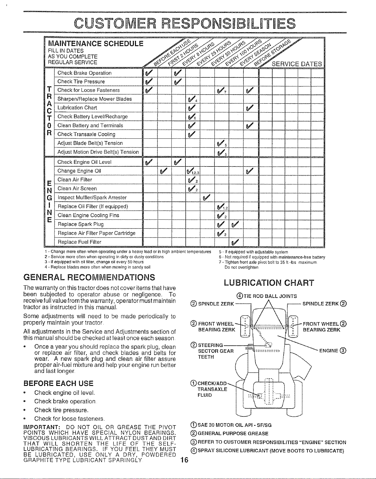
MAINTENANCE SCHEDULE
FILL [N DATES
AS YOU COMPLETE
REGULARSERVICE
! check Brake Operation i'_
CheckTire Pressure 1_ __
T[ CheckforLooseFasteners
Sharpen/Replace MowerBlades
CA! LubricationChart __.
T CheckBatteryLevel!Recharge
CleanBatteryandTerminals
R } CheckTransaxleCooling
AdjustBlade Belt(s)Tension
Adjust MotionDriveBelt(e) Tension
Check Engine Oil Level
I change Engine0il " 6/' _1,2.a ' $/'
E t Clean Air Filter _2 I
N CleanAir Screen _#'2
G Inspect Muffler/Spark Arrester 644
1 ReplaceOil Filter (if equipped) 6_,_
e/
SERVICE DATES
N Clean Engine Cooling Fins $'#'2
Replace Spark Plug ,. _ _4_
Replace Air Filter Paper Cartridge I _"2 ............
ReplaceFuelFilter ............................. I ... 6#4 I
1 * Change mo_-eo_ten when operating under a heavy load or in high ambient temperatures
2 - Sei'vice more often when operating in dirty or dusty conditions
3 -if equipped with oil fitter, change oil every 50 hou_s
4 - Replace btades more otten when mowing in sandy soil
GENERAL RECOMMENDATIONS
The warranty on this tractor does not cover items that have
been subjected to operator abuse or negligence° To
receive full value from the warranty, operator must maintain
tractor as instructed in this manual
Some adjustments will need to be made periodically to
properly maintain your tractor.
All adjustments in the Service and Adjustments section of
this manual should be checked at least once each season
o Once a year you should replace the spark plug, clean
or replace air filter, and check blades and belts for
wear. A new spark plug and clean air filter assure
proper air-fuel mixture and help your engine run better
and last longer.
BEFORE EACH USE
• Check engine oil level.
o Check brake operation
o Check tire pressure.
o Check for loose fasteners
IMPORTANT; DO NOT OIL OR GREASE THE PIVOT
POINTS WHICH HAVE SPECIAL NYLON BEARtNGS.
VISCOUS LUBRICANTS WILL ATTRACT DUST AND DIRT
THAT WILL SHORTEN THE LIFE OF THE SELF-
LUBRICATING BEARINGS. tF YOU FEEL THEY MUST
BE LUBRICATED, USE ONLY A DRY, POWDERED
GRAPHITE TYPE LUBRICANT SPARINGLY
5 - If equipped with adjustable system
6 - Net required if equipped with maintenance4ree battery
7 - Tighten front axle pivot belt to 35 It 4be maximum
Do not overlighten
LUBRICATION CHART
(_TIE ROD BALL JOINTS
(_) SPINDLE ZERK ®
® ®
BEARING ZERK BEARING ZERK
® STEERING
SECTOR GEAR ENGINE ®
TEETH
(9
TRANSAXLE
FLUID
(_) SAE 30 MOTOR OIL API - SF/SG
® GENERAL PURPOSE GREASE
®REFER TO CUSTOMER RESPONSIBILITIES "ENGINE" SECTION
(_) SPRAY SILICONE LUBRICANT (MOVE BOOTS TO LUBRICATE)
16
Page 17
CUSTOMER
i , , ii, i i ,, ,ill ,,,
RESPONSIBILITIES
TRACTOR
Always observe safety rules when performing any mainte-
nancer
BRAKE OPERATION
If unit requires more than six (6) feet stopping distance at
high speed in highest gear, then brake must be adjusted.
(See "TO ADJUST BRAKE" in the Service and Adjust-
ments section of this manual)
TIRES
- Maintain proper air pressure in alt tires (See "PROD-
UCT SPECIFiCATiONS" on page 3 of this manual)..
o Keep tires free of gasoline, oil, or insect control chemi-
cals which can harm rubber
o Avoid stumps, stones, deep ruts, sharp objects and
other hazards that may cause tire damage
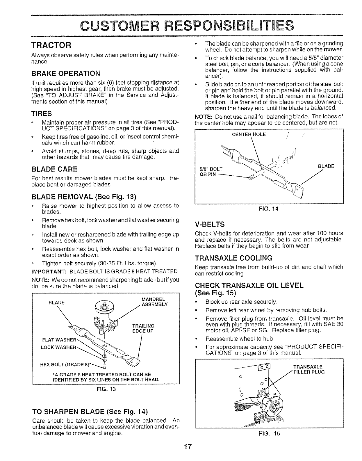
BLADE CARE
For best results mower blades must be kept sharp. Re-
ptace bent or damaged blades
i
o The blade can be sharpened with a file or on agrinding
wheel Do not attempt to sharpen while on the mower
o To check blade balance, you will need a 5/8" diameter
steel bolt, pin, or a cone balancer. (When using a cone
balancer, follow the instructions supplied with baF
ancer),.
o Slide blade on to an unthreaded portion of the steel bolt
or pin and hold the bolt or pin parallel with the ground,
If blade is balanced, it should remain in a horizontal
position. Ifeither end of the blade moves downward,
sharpen the heavy end until the blade is balanced.
NOTE: Do not use a nail for balancing blade. The lobes of
the center hole may appear to be centered, but are not.
CENTER HOLE
5t8" BOLT
OR PIN
/
/
/
BLADE
BLADE REMOVAL (See Fig. 13)
= Raise mower to highest position to allow access to
blades..
• Remove hex bott, lock washer and ffat washer securing
blade
o Install new or resharpened blade with trailing edge up
towards deck as shown.
o Reassemble hex bolt, lock washer and fiat washer in
exact order as shown,
o Tighten bolt securely (30-35 FL Lbs..torque),
IMPORTANT: BLADE BOLT IS GRADE 8HEAT TREATED
NOTE: We do not recommend sharpening blade- but if you
do, be sure the blade is balanced.
MANDREL
AA=SE=BL
....L /
LOCK WASHER ,-_ _ _ _"*%'-, /
HEX BOLT (GRADE B) _'-_-_4 "_
*A GRADE 8 HEAT TREATED BOLT CAN BE
IDENTIF'ED BY SIX LINES ON THE BOLT HEAD,
FIG. 13
FIG. 14
V-BELTS
Check V-belts for deterioration and wear after t00 hours
and replace if necessary. The belts are not adjustable
Replace belts if they begin to slip from wear
TRANSAXLE COOLING
Keep transaxle free from build-up of dill and chaff which
can restrict cooling
CHECK TRANSAXLE OIL LEVEL
(See Fig. '15)
, BIock up rear axie securely
- Remove left rear wheel by removing hub belts.
• Remove filler plug from transaxle.. Oil level must be
even with plug threads. If necessary, fill with SAE 30
motor oil, API-SF or SG Replace filfer plug.
- Reassemble wheel to hub,
, For approximate capacity see "PRODUCT SPECIFI-
CATIONS" on page 3 of this manual..
TRANSAXLE
i
o
O
TO SHARPEN BLADE (See Fig. 14)
Care should be taken to keep the blade balanced° An
unbalanced blade will cause excessive vibration and even-
tual damage to mower and engine
FIG. 15
1"7'
Page 18
CUSTOMER RESPONSMBBLITIES
BA'I-i'ERY
Your tractor has a battery charging system which is suffi_
cient for normal use. However, periodic charging of the
battery with an automotive charger will extend its life_
, Keep battery and terminals clean..
, Keep battery bolts tight.
o Keep smalt vent holes open.
o Recharge at 6-10 amperes for 1 hour..
TO CLEAN BATTERY AND TERMINALS
Corrosion and dirt on the battery and terminals can cause
the battery to "leak" power.
o Remove terminal guard.
• Disconnect BLACK battery cable first then RED bat-
tery cable and remove battery from tractor.,
• Rinse the battery with plain water and dry,
o Clean terminals and battery cable ends with wire brush
until bright.,
o Coat terminals with grease or petroleum jelly,
• Reinstall battery (See "CONNECT BATTERY" in the
Assembly section of this manual).,
ENGINE
Change the oil after the first two hours of operation and
every 50 hours thereafter or at least once a year if the
tractor is not used for 50 hours in one year.,
Check the crankcase oil level before starting the engine
and after each eight (8) hours of operation Tighten oil fill
cap/dipstick securely each time you check the oil level
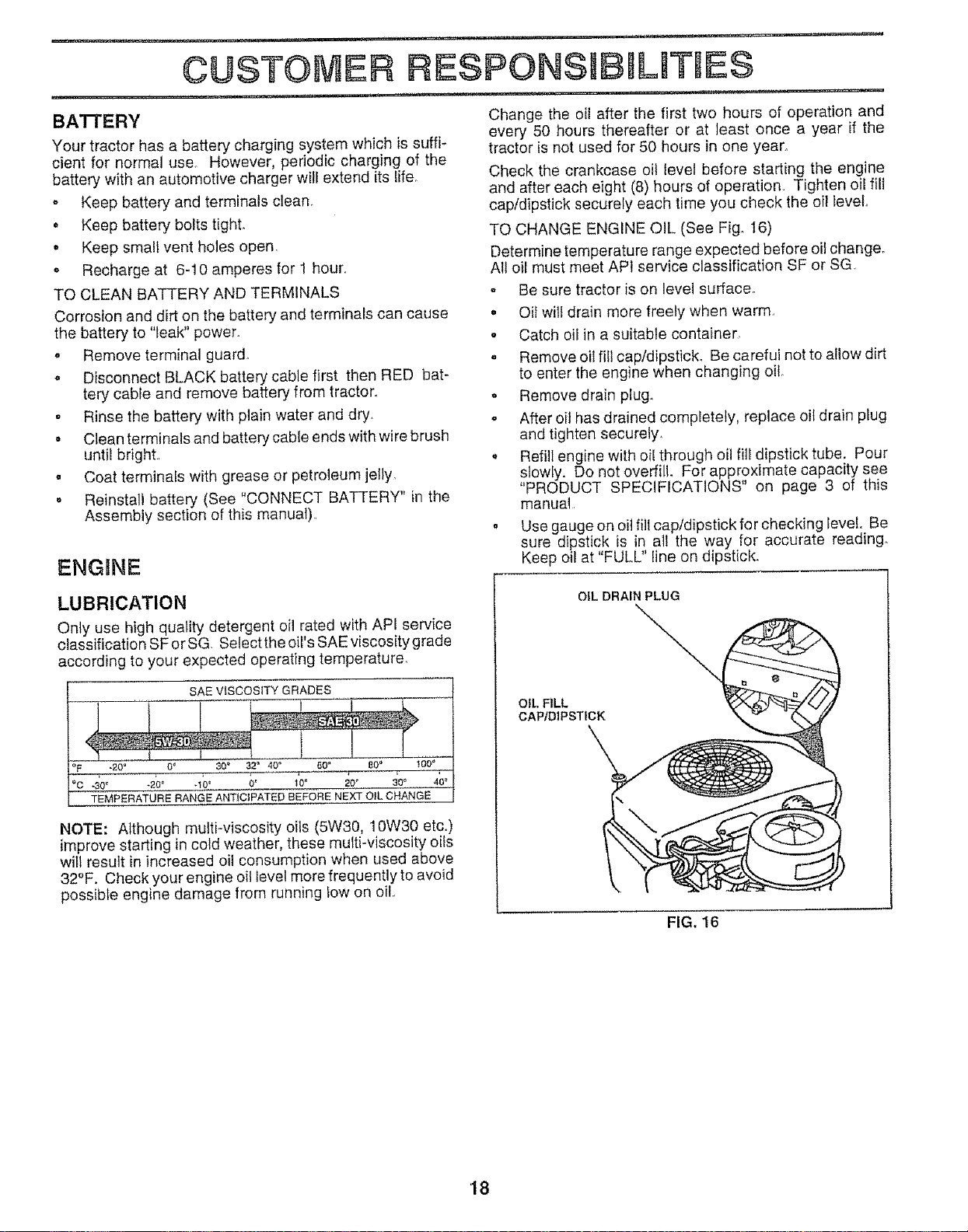
TO CHANGE ENGINE OIL (See Fig. 16)
Determine temperature range expected before oil change.
All oil must meet API service classification SF or SG
- Be sure tractor is on level surface.
, Oil will drain more freely when warm,,
o Catch oil in a suitable container,
o Remove oil fill cap/dipstick. Be careful not to allow dirt
to enter the engine when changing oil
o Remove drain plug.
o After oil has drained completely, replace oil drain plug
and tighten securely,
. Refill engine with oil through oil fill dipstick tube. Pour
slowly. Do not overfill. For approximate capacity see
"PRODUCT SPECIFICATIONS" on page 3 of this
manual
. Use gauge on oil fill cap/dipstick for checking level. Be
sure dipstick is in all the way for accurate reading.
Keep oil at "FULL" line on dipstick.
LUBRICATION
Only use high quality detergent oil rated with API service
classification SForSG. SelecttheoiI's SAEviscositygrade
according to your expected operating temperature.
SAE VISCOSITY GRADES
NOTE: Although multi-viscosity oils (5W30, 10W30 etc,,)
improve starting in cold weather, these multi-viscosity oils
will result in increased oil consumption when used above
32°F. Check your engine oil tevel more frequently to avoid
possible engine damage from running low on oil,
OiL DRAIN PLUG
OIL FILL
CAPtDIPSTICK
FIG. 16
18
Page 19

LJ = JJ_
CUSTOMER FIIESPONS B UT ES
CLEAN AIR SCREEN (See Fig. '17)
Air screen must be kept free of dirt and chaff to prevent
engine damage from overheating° Clean with a wire brush
or compressed air to remove dirt and stubborn dried gum
fibers,,
ENGINE COOLING FINS (See Fig. 17)
Remove any dust, dirt or oil from engine cooling fins to
prevent engine damage from overheating Engine blower
housing must be removed. Remove side panels and hood
(See"TO REMOVE HOOD AND GRILL ASSEMBLY" in the
Service and Adjustments section of this manual)
COOLING FINS
(BOTH SIDES)
AIR SCREEN
COVER ",",
CARTRIDGE
PLATE _-'_,-- _'_"'_-'--._
,:__--,
__"-'_ WING NUT
SEAL
c
@
FIG. 18
MUFFLER
Inspect and replace corroded muffler and spark arrester (if
equipped) as it could create a fire hazard and/or damage.
SPARK PLUGS
Replace spark plugs at the beginning of each mowing
season or after every I00 hours of operation, whichever
comes first, Spark plug type and gap setting are shown in
"PRODUCT SPECIFICATIONS" on page 3 of this manuat.
FIG. 17
AIR FILTER (See Fig. 18)
Your engine will not run properly using a dirty air filter.
Clean the foam pre-cteaner element after ever*/25 hours of
operation or every season,. Service paper cartridge every
100 hours or every season, whichever occurs first.
Service air cleaner more often under dusty conditions.
o Remove wing nut and cover.
o Remove seat and cartridge plate
TO SERVICE PRE-CLEANER
• Slide foam pre-cieaner off cartridge..
o Wash it in liquid detergent and water.
Squeeze it dry in a clean cloth.
° Saturate it in engine oil Wrap it in clean, absorbent
cloth and squeeze to remove excess oil.
TO SERVICE CARTRIDGE
o Gently tap the flat side of the paper cartridge to dis-
lodge dirt. Do not wash the paper cartridge or use
pressurized air, as this wilt damage the cartridge
Replace a dirty, bent, or damaged cartddge_
o Reinstall the pre-cleaner (cleaned and oiled) over the
paper cartridge.
• Reassemble air cleaner, cartridge plate, and seat..
o Install the air cleaner cover and wing nut. Tighten wing
nut 1/2turn to I full turn after nut contacts cover. Do not
overtighten.
ENGINE OIL FILTER
Replace the engine oil filter every season or every other oil
change if the tractor is used more than 100 hours in one
year.
IN-LINE FUEL FILTER (See Fig. 19)
The fuel fitter should be replaced once each season. If fuet
filter becomes clogged, obstructing fuel flow to carburetor,
replacement is required..
o With engine cool, remove filter and plug fuel line
sections.
. Ptace new fuel filter in position in fuel fine with arrow
pointing towards carburetor
o Be sure there are no fuel line leaks and clamps are
property positioned
o Immediately wipe up any spilled gasoline
CLAMP .._ ,,. CLAMP
FUEL FILTER
FtG_ 19
CLEANING
• Clean engine, battery, seat, finish, etc of all foreign
matter.
• Keep finished surfaces and wheels free of all gasoline,
oil, etc.
• Protect painted surfaces with automotive type wax_
We do not recommend using a garden hose to clean your
tractor unless the electrical system, muffler, air filter and
carburetor are covered to keep water ouL Water in engine
can result in a shortened engine life
19
Page 20

SERVICE AND ADJUSTMENTS
--- -- I, 'UllU ' II _ I,I
CAUTION: BEFORE PERFORMING ANY SERVICE OR ADJUSTMENTS,
o Place gearshift lever in neutral (N) position.
o Depress clutch/brake pedal fully and set parking brake,
Place attachment clutch in "DISENGAGED" position.
• Turn ignition key "OFF" and remove key,
Make sure the blades and all moving parts have completely stopped,
o Disconnect spark plug wire from spark plug and place wire where it cannot come in contact
with plug,
TO REMOVE MOWER (See Figi 20) .... TO LEVEL MOWER HOUSING
• Place attachment clutch in "DISENGAGED" position Adjust the mower while tractor is parked on level ground or
o Turn height adjustment knob to lowest setting driveway,. Make sure tires are properly inflated (See
• Lower mower to its lowest position. If tires are over or underinflated, you will not properly adjust
o Remove retainer spring holding anti-swaybar to chas- your mower.
sis bracket and disengage anti-swaybar from bracket SiDE-TO-SIDE ADJUSTMENT (See Figs_ 20 and 21)
° Remove retainer springs from suspension arms at o Raise mower to its highest position.
deck and disengage arms from deck° ° Measure height from bottom of deck curl to ground
° Raise attachment lift to its highest position., level at front corners of mower. Distance "A" on both
o Remove two retainer springs from each front link and sides of mower should be the same.
remove links, o if adjustment is necessary, make adjustment on one
• Slide mower forward and remove belt from e!ectric
clutch pulley, nut on that side.
° Slide mower out from under right side of tractor, o To lower one side of mower, loosen lift link adjustment
IMPORTANT: IF AN ATTACHMENT OTHER THAN THE nut on that side.
MOWER DECK IS TO BE MOUNTED ON THE TRACTOR, NOTE: Each full turn of adjustment nut will change mower
REMOVE THE FRONT LINKS height about 3/16".
TO INSTALL MOWER ° Recheck measurements after adjusting_
, i .... i,u u,i,,, L
PRODUCT SPECIFICATIONS on page 3 of this manual)..
side of mower only.
o To raise one side of mower, tighten lift link adjustment
DRIVE BELT" in the Assembly section of this manualr OFCURL
AO,UST.ENT
NUTS LIFT FRONT "" -
LINKS SUSPENSION FIG. 21
ARMsSUSPENS1ON BRACKET _
FRONT MOWER \
BRACKET
CHASSIS
RETAINER
SPRING
ANTI-SWAY
BAR RETAINER
SPRINGS
...._ {_--- OF CURL
FRONT
SUSPENSION
BRACKET
RETAINER
SPRINGS
FRONT MOWER
BRACKET
FIG. 20
2O
Page 21

SERVICE AND ADJUSTMENTS
, m , i , ii u
FRONT-TO-BACK ADJUSTMENT (See Figs. 22 and 23) -
IMPORTANT: DECK MUST BE LEVEL SIDE-TO-SIDE. IF
THE FOLLOWING FRONT-TO-BACK ADJUSTMENT tS
NECESSARY, BE SURE TO ADJUST BOTH FRONT LINKS
EQUALLY SO MOWER WILL STAY LEVEL SfDE-TO-SlDE,,
To obtain the best cutting Jesuits, the mower housing
should be adjusted so the front is approximately 1t8" to 1/2"
lower than the rear when the mower is in its highest
position.
Check adjustment on right side of tractor, Measure dis-
tance "F" directly in front of and behind the mandrel at
bottom edge of mower housing as shown.
. Before making any necessary adjustments, check that
both front links are equal in length.
o tf links are not equal in length, adjust one !ink to same
length as other tink_
• To lower front of mower housing, loosen nut"G" on both
front links an equal number of turns.
• When distance "F" is 1/8" to 1/2" lower at front than
rear, tighten nut"H" against trunnion on both front links,
. To raise front of mower housing, loosen nut "H" from
trunnion on both front links. Tighten nut "G" on both
front links an equal number of turns
. When distance "F" is 1/8" to 1/2" lower at front than
rear, tighten nut "H" against trunnion on both front
links.
NOTE: Each full turn of nut "G" wilt change dim, "F" by
approximately 3/8".,
• Recheck side-to-side adjustment
TO REPLACE MOWER DRIVE BELT
MOWER DRIVE BELT REMOVAL (See Fig, 24) -,
. Park tractor on a level surface, Engage parking brake
o Remove four screws from L,H, mandrel cover and
remove cover,
° Roll belt over the top of LH, mandrel pulley,
• Remove belt from electric clutch pulley,
• Remove belt from idter pulleys
. Remove any dirt or grass clippings which may have
accumulated around mandrels and entire upper deck
surface,
• Check primary idler arm and two idlers to see that they
rotate freely,
o Be sure spring is securely hooked to primary idler arm
and bolt in mower housing,
MOWER DRIVE BELT INSTALLATION (See Fig 24)
, Install belt in both idlers. Make sure belt is in both belt
keepers at the idlers as shown,
- Install new belt onto electric clutch pulley,
Roll belt into upper groove of LH mandrel pulley.
o Carefully check belt routing making sure beft is in the
grooves correctly and inside belt keepers.
. Reassemble L.H. mandrel cover,
_',.% I ,7_ 1, MANDREL
%, ," Io
'q_@.;;' I ''F'' "F"t "_
FIG. 22
BOTH FRONT LINKS SHOULD BE EQUAL IN LENGTH
NUT "G"
NUT "H"
L.H. SCREWS
MANDREL
COVER "X_.,
"!!ilr'
IDLER ARM
BELT
KEEPERS
IDLER
PULLEYS
FIG., 24
ELECTRIC
CLUTCH
PULLEY
f
FRONT LINKS
TRUNNION
FIG. 23
21
Page 22

SERVICE AND ADJUSTMENTS
uJJ_t
TO REPLACE MOWER BLADE DRIVE BELT
(See Fig. 25)
Park the tractor on level surface. Engage parking brake.
o Remove mower drive belt (See'%O REPLACE MOWER
DRIVE BELT in this section of th{s manual).
= Remove mower (See "TO REMOVE MOWER" in this
section of this manual)..
, Remove four screws from R..H, mandrel cover and
remove cover. Unhook spring from bolt on mower
housing°
, Carefully roll belt off R,H. mandrel pulley,,
. Remove belt from center mandrel pulley, idler pulley,
and LH, mandrel pulley.
o Remove any dirt or grass which may have accumu-
lated around mandrels and entire upper deck surface.
° Check secondary idler arm and idler to see that they
rotate freely,
• Be sure spring is hooked in secondary idler arm and
sway-bar bracket.
• install new belt in lower groove of LH° mandrel pulley,
idler pulley, and center mandrel puliey as shown.
, Roll belt over R.H mandrel pufiey, Make sure belt is in
all grooves properly,
o Reconnect spring to bolt in mower housing and rein-
stall RH, mandrel cover.
, Reinstall mower to tractor (See"TO INSTALL MOWER"
in the Assembly section of this manual),,
o Reassemble mower drive belt (See "TO REPLACE
MOWER DRIVE BELT" in this section of this manual).
L.H, MOWER CENTER
MANDREL BLADE
DRIVE BELT MANDREL
IDLER
PULLEY
R_R.
MANDREL
COVER
NOTE: After installing a new electric clutch, run tractor at
full throttle and engage and disengage electric clutch 10
cycles to wear in clutch plate.
ROTOR \ CLUTCH PLATE
SLOT (3). '_;_ ,,
012
/ \
NYLON LOCKNUT (3) BRAKE PLATE
FIG° 26
TO ADJUST BRAKE (See Fig. 27)
Your tractor is equipped with an adjustable brake system
which is mounted on the left side of the transaxle.
If tractor requires more than six (6) feet stopping distance
at high speed in highest gear',then brake must be adjusted.
Depress clutch/brake pedal and engage parking brake.
° Measure distance between brake operating arm and
nut "A" on brake rod.
, If distance is other than 1-3/4", toosen jam nut and turn
nut "A" until distance becomes 1"3/4"r Retighten jam
nut against nut "A"o
° Road test tractor for proper stopping distance as stated
above. Readjust if necessary. If stopping distance is
still greater than six (6) feet in highest gear, further
maintenance is necessary. Contact your nearest au-
thorized service center/department.
WITH PARKING BRAKE "ENGAGE"
SECONDARY
IDLER ARM
SPRING SWAY-BAR
BRACKET
FIG, 25
SCREW
TO ADJUST ATTACHMENT CLUTCH
(See Fig. 26)
The electric clutch should provide years of service. The
clutch has a buittqn brake that stops the pulley within 5
seconds° Eventually, the internal brake will wear which
may cause the mower blades to not engage, or, to not stop
as require& Adjustments should be made by your nearest
authorized service center!department.
o Make sure attachment clutch and ignition switches are
in "OFF" position r
O Adjust the three nylon locknuts until space between
clutch plate and rotor measures _012" at all three slot
locations cut inside of brake plate
OPERATING
ARM JAM NUT
®
FIG, 27
22
Page 23

SERVICE AN[:) ADJUSTMENTS
ii ,,, 1111111,1 , ,,, ,i i111 ,i ,,i1,
TO REPLACE MOTION DRIVE BELT
(See Fig. 28)
Park the tractor on level surface, Engage parking brake.
For ease of service there is a belt installation guide decat on
bottom of left footrest, ]tis not necessary to remove mower,
BELT REMOVAL -
o Engage parking brake (creates slack in belt)
o Remove mower drive belt from electric clutch pulley
only (See "TO
this section of this manual).
• Roll motion drive belt off transaxle pulley.
• Roll belt off clutching idler pulleys, then off engine
pulley and front V-idler pulley
° Pull belt out of all belt keepers.
BELT INSTALLATION -
• Place V part of belt into grooves on engine pulley and
front V-idler, making sure to route belt inside of belt
keepers,
• Put bett coming from V-idler above midspan bett keeper,
then onto clutching idler pu!teys as shown.
. Make sure V part of belt engages V-idler.
° Place beit around transaxle pulley, beginning at top,
V part of belt should engage transaxle pulley.
o Place long lower section ofbelt through loop inmidspan
belt keeper.
o Check to be sure belt is on proper side of all belt
keepers.
• Reinstall mower drive belt onto electric clutch pulley
IMPORTANT: CHECK BRAKE ADJUSTMENT
REPLACE MOWER DRIVE BELT" Jn
TO ADJUST STEERING WHEEL ALIGNMENT
If steering wheel crossbars are not horizontal (left to right)
when wheels are positioned straight forward, remove steer-
ing wheel and reassemble per instructions in the Assembly
section of this manual
FRONT WHEEL TOE-IN ADJUSTMENT
Front wheel toe-in is required for proper steering operation.
Toe-in was set at the factory and adjustment should not be
necessary, if parts in the front axle or steering mechanism
have been replaced or damaged, check toe-in and adjust
if necessary.,
TO CHECK TOE-IN (See Fig 29) -
- Position front wheels straight ahead
. Measure distance between wheels at front and rear of
tires (dimensions "A" and "B").
o Front dimension "A" should be 1/8" to 1/4" less than
rear dimension "B"o
TO ADJUST TOE-IN (See Figs, 29 and 30) -
o Loosen jam nuts at adjustment sleeves on tie rod.,
• Adjust tie roduntil dimension "A" is 1/8" to t/4" less than
dimension "B".
• Tighten jam nuts securely.,
TRACTOR V-BELT DRIVE SCHEMATIC
VIEWED FROM LH, SIDE OF TRACTOR
CLUTCHING tKEEPER
ENGINE
PULLEY 3ELT\
V-IDLER
KEEPER BELT
PULLEY KEEPER PULLEY
FLATIDLER
TWISTS
AS VIEWED FROM BOTTOM
FIG, 28
CLUTCHING
IDLER
BELT TRANSAXLE
BELT
FIG. 29
ADJUSTMENT SLEEVES
TIE ROD
i
JAM NUTS
FIG, 30
FRONT WHEEL CAMBER
The front wheel camber is not adjustable on your tractor, If
damage has occurred to affect the front wheel camber,
contact your nearest authorized service centeddepart-
menL
23
Page 24

TO REMOVE WHEEL FOR REPAIRS
FRONT WHEEL (See Fig 31) -
= Block up axle securely,
• Remove axle cover, retaining ring and washers to allow
wheel removal
• Repair tire and reassemble
o Replace washers and snap retaining ring securely in
axle groove
- Replace axle cover
WASHERS
RETAIN|NG
RING
AXLE
COVER
FIG. 3't
REAR WHEEL -
o Block rear axte securely
o Remove five (5) hub bolts to allow wheel removal
o Repair tire and reassemble Replace and tighten hub
bolts securely
TO START ENGINE WITH A WEAK BATTERY
(See Figs. 32)
CAUTION: Lead-acid batteries garter-
and smoking materials away from bat-
ate explosive gases. Keep sparks, flame
teries. Always wear eye protection
when around batteries.
If your battery is too weak to start the engine, it shoutd be
recharged. If "jumper cables" are used for emergency
starting, foIlow this procedure:
IMPORTANT: YOUR TRACTOR IS EQUIPPED WiTH A 12
VOLT NEGATtVE GROUNDED SYSTEM THE OTHER
VEHICLE MUST ALSO BE A 12 VOLT NEGATIVE
GROUNDED SYSTEM. DO NOT USE YOUR TRACTOR
BATTERY TO START OTHER VEHICLES
TO ATTACH ,JUMPER CABLES -
o Connect each end of the RED cable to the POSITIVE
(+) terminal of each battery, taking care net to short
against chassis
o Connect one end of the BLACK cable to the NEGA-
TIVE (-) terminal of fulty charged battery.
• Connect the other end of the BLACK cabte to a panel
bolt on the left side of the tractor, away from fuei tank
and battery.
TO REMOVE CABLES, REVERSE ORDER -
, BLACK cable first from chassis and fully charged battery.
o RED cable last from both batteries.
"POSITIVE" "NEGATIVE"
(+) . I.)
O
PANEL
BOLT
FIG. 32
TO REPLACE HEADLIGHT BULB
o Raise hood,
• Pull bulb holder out of the hole in the backside of the
gdlL
Replace bulb in holder and push bulb holder securely
back into the hole in the backside of the grill
o Close hood,
INTERLOCKS AND RELAYS
Loose or damaged wiring may cause your tractor to run
poorly, stop running, or prevent it from starting
. Check wiring,, See electrical wiring diagram in Repair
Parts section of this manual,
TO REPLACE FUSE
Replace with 30 amp automotive-type plug-in fuse, The
fuse hotder is located behind the dash_
24
Page 25

i , i , ii,i i , ii , i , i iii i
SERVmCE AN ADJUSTMENTS
TO ADJUST ATTACHMENT LIFT SPRING
(See Fig. 33)
o While holding spring bushing with wrench, loosen jam
nut°
, Turn adjustment boit clockwise to extend spring and
reduce lift effort (for heavier attachments),
, Turn adjustment bolt counterclockwise for fighter at-
tachments,
, Retighten jam nut against spring bushing..
IMPORTANT: DO NOT ADJUST FOR MAXIMUM SPRING
TENSION WHEN USING LIGHT ATTACHMENTS SUCH
AS A MOWER. ADJUST LIFT LEVER SPRING TO AID IN
LtFT1NG ATTACHMENT. DO NOT OVERPOWER SPRING.
WHEN REMOVING ATTACHMENT, ALWAYS ADJUST
SPRING TENSION TO ITS LOWEST POSITION.
ADJUSTMENT
JAM NUT LIFT SPRING
SPRING BUSHING
o ATTACHMENT
TO REMOVE HOOD AND GRILL ASSEMBLY
(See Fig, 34)
o Raise hood_
. Unsnap headlight wire connector
o Stand infront oftractor. Grasp hood at sides, tilt toward
engine and lift off of tractor.
o To replace, reverse above procedure..
HEADLIGHT
_ WIRE
CONNECTION
HOOD
° oJ
o o
FIG, 33
FIG. 34
25
Page 26

SIERV OE AND ADJUSTMENTS
ENGINE
TO ADJUST THROTTLE CONTROL CABLE
(See Fig. 35 and 36)
The throttle control has been preset at the factory and
adjustment should not be necessary Check adjustment as
described below before loosening cable. If adjustment is
necessary, proceed as follows:
o With engine not running, move throttle control lever to
fast (,f_) position.
• Checkthat speed control lever is against step screw. If
it is not loosen casing clamp screw and pull throttle
cable until lever is against screw. T ghten c amp screw
securely.
TO ADJUST CARBURETOR (See Fig. 37)
The carburetor has been preset at the factory and adjust-
ment should not be necessary However, minoradjustment
may be required to compensate for differences in fuel,
temperature, altitude or load If the carburetor does need
adjustment, proceed as follows:
In general, turning the adjusting needles in (clockwise)
decreases the supply of fuel to the engine giving a leaner
fuel/air mixture. Turning the adjusting needles out (coun-
terclockwise) increases the supply of fuel to the engine
giving a richer fuel!air mixture.
IMPORTANT" DAMAGE TO THE NEEDLES AND THE
SEATS IN CARBURETOR MAY RESULT IF SCREW tS
TURNED IN TOO TIGHT
PRELIMINARY SETTING -
o Be sure you have a clean air fiiter, and the throttle
control cable is adjusted properly (see above),
,, With engine off turn idle fuel adjusting needle in (clock-
wise) dosing it finger tight and then turn out (counter-
clockwise) 1-II4 turns.
o Turn main fuel adjusting needle in (clockwise) closing
finger tight and then turn out (countercfockwise) l turn.
FINAL SETTING -
o Start engine and alfow to warm for five minutes.. Make
final adjustments with engine running and shift/motion
control lever in neutral (N) position.
o With throttle control lever in fast ( '_ ) position, turn
main fuel adjusting needle in (clockwise) until engine
beg!ns to die then turn out (counterclockwise) until
engine runs rough Turn needle to a point midway
between those two positions.
o Idle speed setting - With throttle control lever in slow
(_) position, engine should idle at 1400 RPM If
engine idles too slow or fast, turn idle speed adjusting
screw in or out until correct idle is attained
• Idle fuel needle setting - With throttle control lever in
slow (,_) position, turn idle fuel adjusting needle in
(clockwise) until engine begins to die and then turn out
(counterclockwise) until engine runs rough..Turn needle
to a point midway between those two positions
• Recheck idle speed. Readjust if necessary.
ACCELERATION TEST -
o Move throttle control lever from slow (,_m.) to fast (,@)
position. If engine hesitates or dies, turn idle mixture
screw out (counterclockwise) 1/8 turn.. Repeat test and
continue to adjust, if necessary, until engine acceler-
ates smoothly.
High speed stop is factory adjusted. Do not adjust-damage
may resulL
IMPORTANT: NEVER TAMPER WITH THE ENGINE
GOVERNOR, WHICH IS FACTORY SET FOR PROPER
ENGtNESPEED OVERSPEEDINGTHEENGINEABOVE
THE FACTORY HIGH SPEED SETTING CAN BE
DANGEROUS, IF YOU THINKTHE ENGINE-GOVERNED
HIGH SPEED NEEDS ADJUSTING, CONTACT YOUR
NEAREST AUTHORIZED SERVICE CENTER/
DEPARTMENT, WHICH HAS PROPER EQUIPMENT AND
EXPERIENCE TO MAKE ANY NECESSARY
ADJUSTMENTS
CASING STOPSCREW SPEED CONTROL
CLAMP LEVER
THROTTLE
CONTROL
CABLE
FIG, 35
STOP
SCREW
SPEED
CONTROL
LEVER
FIG, 36
IDLE SPEED
ADJUSTING
SCREW ,--,..,,.---"
_x_ /IDLEFUEL
ADJUSTING
26
FIG,. 37
Page 27

= ,, = ,, =,,,,.=,,,.=,,, ,
STORAGE
,11 i I.u,N.i,,,
Immediately prepare your tractor for storage at the end of
the season or if the tractor will not be used for 30 days or
more r
gasoline in the tank inside a building
where fumes may reach an open flame
CAUTION: Never store the tractor with
or spark. Allow the engine to cool
before storing in any enclosure,
TRACTOR
Remove mower from tractor for winter storage° When
mower is to be stored for a period of time, clean it thor-
oughly, remove all dirt, grease, leaves, etc. Store in a
clean, dry area.
o Clean entire tractor (See"CLEANING" in the Customer
Responsibilities section of this manual).
o Inspect and replace belts, if necessary (See belt re-
placement instructions in the Service and Adjustments
section of this manual),
o Lubricate as shown in the Customer Responsibilities
section of this manual
o Be sure that all nuts, bolts and screws are securely
fastened, Inspect moving parts for damage, breakage
and wear. Replace if necessary.
• Touch up al! rusted or chipped paint surfaces; sand
lightly before painting.
BATTERY
. Fully charge the battery for storage.
o After a period of time in storage, battery may require
recharging,
o To help prevent corrosion and power leakage during
long periods of storage, batter:/ cables should be
disconnected and battery cleaned thoroughly (see "TO
CLEAN BATTERY AND TERMINALS in the Cus-
tomer Responsibilities section of this manual),
° After cleaning, leave cables disconnected and place
cables where they cannot come in contact with battery
terminals
. Be sure battery drain tube is securely attached.
. tf battery is removed from tractor for storage, do not
store battery directly on concrete or damp surfaces.
ENGINE
FUEL SYSTEIVl
IMPORTANT: tT IS IMPORTANT TO PREVENT GUM
DEPOSITS FROM FORMING IN ESSENTIAL FUEL
SYSTEM PARTS SUCH AS CARBURETOR, FUEL FILTER,
FUEL HOSE, OR TANK DURING STORAGE, ALSO,
EXPERIENCE INDICATES THAT ALCOHOL BLENDED
FUELS (CALLED GASOHOL OR USING ETHANOL OR
METHANOL) CAN ATTRACT MOISTURE WHICH LEADS
TO SEPARATION AND FORMATION OF ACIDS DURING
STORAGE ACIDIC GAS CAN DAMAGE THE FUEL
SYSTEM OF AN ENGINE WHILE IN STORAGE,
o Drain the fuel tank.
• Start the engine and Iet it run until the fuel lines and
carburetor are empty,
• Never use engine or carburetor cleaner products in the
rue! tank or permanent damage may occur.
o Use fresh fuel next season.
NOTE: Fuel stabilizer is an acceptable alternative in
minimizing the formation of fuel gum deposits during stor-
age., Add stabilizer to gasoline in fuel tank or storage
container. Always foltow the mix ratio found on stabilizer'
container. Run engine at least 10 minutes after adding
stabilizer to allow the stabilizer to reach the carburetor. Do
not drain the gas tank and carburetor if using fuel stabilizer
ENGINE OIL
Drain oil (with engine warm) and replace with clean engine
oil. (See "ENGINE" in the Customer Responsibilities
section of this manual),
CYLINDERS
• Remove spark plug(s).
o Pour one ounce of oil through spark plug hole(s) into
cylinder(s).
• Turn ignition key to"START" position for a few seconds
to distribute oil
• Replace with new spark plug(s)
OTHER
o Do not store gasoline from one season to another
• Replace your gasoline can if your can starts to rusL
Rust and/or dirt in your gasoline will cause problems°
• ff possible, store your tractor indoors and cover it to
give protection from dust and dirt.,
• Cover your tractor with a suitable protective cover that
does not retain moisture. Do not use plastic. Plastic
cannot breathe which aItows condensation to form and
will cause your tractor to rust.
IMPORTANT: NEVER COVER TRACTOR WHILE ENGINE
AND EXHAUST AREAS ARE STILL WARM
27
Page 28

TROUBLESHOOTING POINTS
, , i i .... xl_,l_, i i i,i ii .,i u ,,,,,,
PROBLEM
Wilt not start
Hard to start
Engine witl not turn over
CAUSE
1 Out of fuel
2 Engine not"CHOKED" properly
3 Engine flooded
4 Bad spark plug
5 Dirty air filter
6 Dirty fue! fitter
7 Water in fuet
8. Loose or damaged wMng
9 Carburetor out of adjustment
10 Engine valves out of adjustment
1 Dirty air fitter,
2 Bad spark plug.
3 Weak or dead battery
4 Dirty fuel filter
5 Stale or dirty fuel
6 Loose or damaged wiring
7 Carburetor out of adjustment
8 Engine valves out of adjustment
t Clutchlbrake pedal not depressed
2 Attachment clutch is engaged.
3 Week or dead battery
4 Blowr _e
5. Corro,.,_ 'Iery terminals
6 Loose or u ged wiring
7 Faulty ignifioh, _4tch
8 Faulty solenoid or starter
9 Fautty operator presence switch(es)
CORRECTION
1 Fill fuel tank
2. See "TO START ENGINE" in Operation section
3 Wait severa] minutes before attempting to start
4 Replace spark plug
5 Cteanireplace air filter
6 Replace fuel filter
7 Drain fuel tank and carburetor, refill tank with fresh
gasoline and replace fuel filter.
8 Check all wtr_ng
g, Contact an authorized service eenteddepartment
10 Contact an authorized service center/department
i Clean/rep{aee air filter
2 Replace spark plug,
3 Recharge or replace battery
4, Replace fuel filter
5 Drain fuel tank and refil! with fresh gasoline
6 Check all wiring
7 Contact an authorized service center/department
8 Contact an authorized service center/department.
1 Depress clutch/brake pedal
2 Disengage attachment dutch
3 Recharge or replace battery
4 Replace fuse
5 Clean battery terminate.
6. Check all wiring
7 Check/replace ignition switch
8 ChecWreplace solenoid orsfarter
9 Contact an authorized service centeddepartment
Engine slicks but will not
start
Loss of power
Excessive vibration
1 Weak or dead batlery
2 Corroded battery terminals
3 Loose or damaged wtdng
4 Faulty solenoiQ or starter
1 Cutting too much grass/too fast
2 Throttle {n "CHOKE" position,
3 Bui_d-up of grass, leaves and trash under mower
4 Dirty air fiIter
5 Low oil level!dirty oil
6 Faulty spark plug
7 Dirty |uei fitter
8 Stale or di,,ty fuel
9 Water in fl_el
10 Spark piug wire loose
t I Dirty engine air screerv'fins
12 Dirty/dogged muffler,
!3 Loose or damaged wiring
14 Carburetor out of adjustment
15 Engine valves out of adjustment
I Worn, bent or loose blade
2 Bent blade mandrel
3 Loose/damaged part{s)
t Recharge or replace batten/
2 Clean battery terminals
3, Check all wiring
4., Check/replace solenoid or starter
I, Set tn "Higher Cut" position/reduce speed
2 Adjust throttle control
3 Ctean underside of mower housing
4. Clean/replace air filter•
5 Check oiltevel/change oil
6 Clean and regap or change spah< plug
7 Replace fuel filter
8, Drain fuel tank and refill with fresh gasoline,
g Drain rue! tank and carburetor, rafiil tank with fresh
gasoline and replace fuel tilter
10 Connect and tighten spark plug wire
1t Cfean engine air screen/fins
12, Clean/replace muffler
13 Checkall wiring
14, Contact an authorized service eenter/deparlment
15 Contact an authorized service center/department
1 Replace blade Tighten blade bolt
2 Replace blade mandrel
3, Tighten !oose part{s) Replace damaged parts
28
Page 29

TROUBLESHOOTING
POINTS
PROBLEM
Engine continues to run
when operator leaves seat
with attachment clutch
engaged
Poor cut - uneven
Mower blades will not
rotate
Poor grass discharge
CAUSE
i ,nl,i ,, i i
1 Faulty operator-safety presence control system
1 Worn, bent or $oose blade
2 Mower deck not levet
3 Buildup of grass, reaves, and trash under mower
4, Bent blade mandre{
5 Clogged mower deck vent holes from buildup of
grass, leaves, and trash around mandrels
1 Obstruction in clutch mechanism
2 Worn/damaged mower drive belt
3 Frozen idler pulley
4 Frozen blade mandrel
t Engine speed too slow
2 Travel speed too fast
3 Wet grass
4 Mowerdeck nettevel
5 Low/uneven tire air pressure
6 Worn, bent or loose blade.
7 Buildup of grass, leaves and trash under mower.
8 Mower drive belt worn
g Blades improperly installed.
10 Improper blades used
11 Clogged mower deck vent holes from buildup of
grass, leaves, and trash around mandrels
CORRECTION
1 Check wiring, switches and connections If not
corrected, contact an authorized service center/
department
t Replace blade Tighten blade bolt
2 Level mower deck
3 Ctean underside of mower housing
4 Replace blade mandrel
5 Clean around mandrels to open vent holes
t, Remove obstruction
2 Replace mower drive belt
3 Replace idler pulley
4 Replace blade mandrel,
I. Place throttle control in "FAST" position
2 Shift to slower speed
3 Allow grass to dry before mowing
4, Level mower deck
5 Check tires for proper air pressure
6 Replace/sharpen blade Tighten blade bo_t
7 CIean underside of mower housing
8. Replace mowerdrive belt
9 Reinstall biades sharp edge down.
10. Replace with blades listed in this manual.
11 Clean around mandrels to open vent hotes
Headlight(s) not working
(if so equipped)
Battery wiil not charge
Engine "backfires"
when turning engine
"OFF"
I Switch is "OFF'
2 Bulb(s) burned out
3 Faulty tight switch,
4 Loose or damaged wiring
5 Blown fuse,
t Bad battery celt(s)
2 Poor cable connections
3 Faulty regulator (if so equipped).
4 Faulty alternator
Engine throttIe control not set at "SLOW"
position for 30 seconds before stopping engine
I. Turn switch "ON_'
2. Replace butb(s).
3 Check/replace light switch
4 Check wiring and connections
5. Replace fuse
t
Replace battery
2
Check!clean all connections
3
Replace regulator
4
Replace alternator
1
Move throttte control to "SLOW" position and at{ow
to idle for 30 seconds before stopping engine
29
Page 30

SERVICE NOTES
30
Page 31

SCHEMATIC
TRACTOR - MODEL NUMBER 917.251480
I IGNITION
t SWITCH
f_kAeK
RED
RED
WHITE
o111 o AoK
°1 °
BATTERY
FUSE 30 AMP, [ J
d_\_ L RED , RED
/ I C _ I _ f_ _ STARTER
-- °-_'___)__.L _ , ' O SOLENOID
CLUTCH / BRAKE l t
(PEDAL UP) ', B I ELECTRIC CLUTCH
)
j I F '
RED "f-_ I 1..........
---2 _-J ; f"",_-',_L. , f--., BLACK
.... / _rW_jLjT'_j-----_
I
J
_;A ;J,
SEAT SWITCH F-t.tvF"_ f.-. I
(NOT OCCUPIED) I ' "_-J'_,
.... 4 .... _ I _ U '
, _ I _--_d-_
It2,_
Q
$
'_T____ j (DISENGAGED,
l
GROUNDING CONNECTOR
BLACK
IGNITION SWITCH
POSITION CIRCUIT
OFF M + G
ON B+L
START B + S + L
BLACK
RED
ORANGE
at IGNITION _ SPARK
CHARGING SYSTEM OUTPUT
15 AMP DC @ 3600 RPM _;_
UNIT PLUGS
REGULATOR L_OW
,'©--_Q _owN
HEADL,G.T!__@__j
SW,TOHlOaF)
O
NON-REMOVABLE
CONNECTIONS
WIRING INSULATED CLIPS
NOTE: IF WIRING INSULATED
CLIPS WERE REMOVED FOR
SERVICING OF UNIT, THEY
SHOULD BE REPLACED TO
PROPERLY SECURE YOUR WIRING
O
REMOVABLE
CONNECTIONS
@---4 )
@---4
28 VOLTS AC @ 3600 RPM
(REGULATOR DISCONNECTED}
HEADLIGHTS /
GFC
HH0
E H_B
D _ _ A
PTO SWITCH
POSITIONoFF]]._JCIRCUITc+ G j
ON +F,B+E,A+D
-7
3'I
Page 32

REPb,UF_PARTS
TRACTOR - - MODEL NUMBER 917.2514,80
ELECTRICAL
24
22
1
t /
l I
\
I
I
1
I
I
I
\
33
32
31
11
R
\
,+
/
/
i 51
I
\
/
/
/
32
Page 33

REPAIR PARTS
ELECTRICAL
TI ACTOR - - MODEL NUMBER 917.251480
KEY PART
NO. NO, DESCRIPTION
1 146140 Battery
2 74760412 Bolt Hex Head 1/4-20 x 3/4
3 STD551125 Washer, Lock'1/4
4 STD551025 Washer 9/32 x 5/8 x 16 Ga
6 8TD541025 Nut Fin Hex 1/4-20
7 7697J Tube Plastic
8 7603J Tray, Battery
9 109596X Clamp, Hose
10 145211 Bolt 1/4-20 x 7.5 Zinc
11 145209 Hold down Battery Dash Mount
12 145769 Nut Push Nylon 1/4"
19 10090400 Washer, Lock 1/4
20 73350400 Nut, Jam Hex 1/4-20
21 136850 Harness Socket Light W/4152J
22 4152J Bulb Light
24 4799J Cable, Battery
25 14614.9 Cable, Battery
26 108824X Fuse
28 4207J Cable, Ground
29 121305X Switch, Plunger
30 144921 Switch, Ign
31 140400 Nut, ignition Switch
32 141226 Cover Switch Key
33 140403 Key, Ignition
34 1t0712X Switch, Light
39 109553X Switch, Interlock
40 146065 Harness lgn.
41 17720408 Screw 1/4-20 x 1/2
42 131563 Cover, Terminal
43 145673 Solenoid
45 122822X Ammeter
49 11151000 Washer, Lock Internal Tooth 5/8
50 146283 Switch, PTO
51 140405 Ring Retainer PTO
53 71031008 Screw Hex Washer Hd #10-32 x 1/2
54 73951000 Nut Keps #10-32
NOTE: All component dimensions given in UoS. inches
1 inch = 25.4 mm
33
Page 34

REPAIR PARTS
CHASSIS ANDENCLOSURES
TRACTOR - - MODEL NUMBER 917.251480
t0
9
59
92
38
57
18
15
/
9
53
13
11
68
47
17
48
41
/
68
22 ---_,.
9
47
t
17
19
2O
86
91
56
16
52
17
67
42
2O
77
/
70
24
/
39
34
Page 35

REPABR PARTS
TRACTOR -- MODEL NUMBER 917.251480
CHASSIS AND ENCLOSURES
KEY PART KEY PART
NO. NO. DESCRIPTION NO. NO. DESCRIPTION
1 150253
2 140506
3 136671X558
4 73680700
5 145203
6 150273
7 17720408
8 145166
9 108067X
10 19092016
11 137270
12 137269
13 137271
14 t36673X558
15 136374
16 121794X
17 17490612
t8 136373x428
19 19131312
20 74760616
21 73680600
22 136670X556
24 145243X558
26 17490512
28 145244X558
29 145349
30 145051X014
31 145183
32 141315
33 141314
34 142131
35 19111116
36 74780512
37 121642X558
38 19091216
39 136961
40 142132
Rail, Frame RH 41 17580408
Drawbar, Gt 42 72140608
Panel Asm., Side LH 43 136939
Nut, Crown Lock Hex 7/16-14 Unc 44 136940
Dash, Plastic Black 45 138460
Dash Lower VGT One-Piece 47 17490608
Screw, Thd Cut I/4-20 x 1/2 48 136814
Support, Dash 1-Pc_ Battery 49 136813
Nut, Pal 50 136575
Washer 9/32 x 1-1/4 x 16 Ga. 52 73680500
Rivet, Ratchet Male 53 137304
Washer, Nylon 56 138461
Rivet, Ratchet Female 57 73640400
Hood Asm., Pnt 58 1371t3
Lens, Bar Clear 59 74180412
Cover, Access 60 17490620
Screw, Thdrof 3/8-16 x 3/4 63 19131614
Grille 64 144283
Washer 13/32 x 13/16 x 12 Ga. 67 140737
Bolt, Fin Hex 3/8-16 x 1 68 17490508
Nut, Crowniock 3/8q6 Unc 69 140022
Panel Asmo, Side RH 70 137159
Footrest, RH 77 137308
Screw, Thdroi 5/t6-18 x 3/4 84 142992
Footrest, LH 85 '1449tl
Bracket, Support Dash 86 74760716
Saddle 88 10040700
Bracket, Support 1-Pc Steering VGT 90 11050600
Bracket Asm., Frame Pivot Lh 91 150851
Bracket Asm., Frame Pivot Rh 92 143485X013
Bracket, Engine Support Rear 94 100207K
Washer 11!32x11/16x16Ga. 95 105531X
Bolt, Fin Hex 5/16-18 x 3/4 106 138776
Fender, Pnt. 120 19131616
Washer 9/32 x 3/4 x 16 Ga. - - 8022J
Bracket, Axle Front
Bracket, Support AxLe/Engine
NOTE: All component dimensions given in U.S. inches
1 inch = 25.4 mm
Screw Tap Tire 1/4-20 x 1/2
Bolt, Carriage 3/8-16 x 1
Bracket, Spnsn Front Lh
Bracket, Spnsn Front Rh
Bracket Asm., Susp Chassis Rh
Screw Thdrol 3/8-16 x 1/2
Bracket Asm, Pivot Hood Lh
Bracket Asm, Pivot Hood Rh
Bracket, Chassis Front
Nut, Crownlock 5/16-18
Rod, Support Hood
Bracket Asm, Susp Chassis Lh
Nut, Keps Hex 1/4-20
Bracket Asm., Fender
Screw, Mach Cr 1/4-20 x 3/4
Screw Thdrol 3/8-16 x 1-1/4
Washer 13/32 x 1 x 14Ga.
Washer, Serrated Disc 13/32 x 1
Guide, Belt T/A
Screw, Thd 5/16-18 x 1/2
Shield, Heat
Guide, Belt Mid Span
Shield, Front
Stop, Over Center Mower
Bracket, Support Transaxle
Bolt, Fin Hex 7/16_14 Unc x 1
Washer, Lock HW HLCL. Spr. 7/16
Washer, Lock External Tooth 3/8
Rail, Frame Lh
Plate, Siikscreen Dash
Clip, Fuel Line
Push Nut, Nylon
Screw, Thdrot Hex Head Zinc Mwr
Washer 13/32 x I x 16 Ga.
Plug, Hole
35
Page 36

REPAIR PARTS
GROUND DRIVE
J
J
TRACTOR -- MODEL NUMBER 917.251480
44
38 36
37 6
29
64
35
51 38
34
37
49
52
t5
47
54 66
57
23
67
5
4
12
62
36
Page 37

REPAIR PARTS
GROUND DRIVE
TRACTOR - - MODEL NUMBER 917.251480
KEY PART
NO. NO.
1 9858M1
3 7563R
4 17490508
5 73680600
6 76020412
7 149176
8 12000034
9 140080
10 142509
11 136927
t2 9204H
t3 139419
14 138901
15 19131316
16 143012
17 126909X
18 137104
19 136926
21 232604t2
22 633A109
23 106932X
24 136925
25 136923
26 137552
27 17490528
28 73350600
29 137213
3O 19131616
34 124236X
35 137648
36 149412
37 121749X
DESCRIPTION
Key, Woodruff
Washer, Thrust, Axle
Screw, Thdrol 5/16-18 x 1/2 Tyt
Nut, Crownlock 3/8q6
Pin, Cotter
Hub Asm Wheel Rear
Kiip, Ring
Bolt, Hub
Disc, Brake
Yoke, Brake Disc
Locknut 1/2-20
Washer, Special
Bushing
Washer 13/32 x 13/16 x 16 Ga.
Set, Screw 1/4-28 x 3/4
Spring
Lever, Brake
Cam, Brake Disc
Screw, Fiat Head 1/4-28 x 3/4
Gearshift, Lever Assembly
Knob
Support, Puck Brake
Puck, Brake Top
Spring, Return
Screw, Hex Wsh Thd. 5/16-18 x 1-
314
Nut, HexJam 3/8-16
Brake, Rod
Washer 13/32 x 1 x t6 Ga.
Cap, Plunger
Rod, Parking Brake
Spring, Drive Ground
Washer 25/32 x 1-t/4 x I6 Ga..
KEY PART
NO. NO, DESCRIPTION
38 150035
39 74321016
40 5304J
41 73631000
42 8883R
43 74760412
44 104601X
45 73800400
46 145170
47 138228
48 72110614
49 19131413
50 131494
51 7380060O
52 139123
53 207J
54 138390
55 105706X
56 137153
57 141756
59 122253X
60 122268X
61 137524
62 10040700
63 74760720
64 137649
65 67609
66 140296
67 19131312
68 5142H
69 136327
NOTE: All component dimensions given in U,S. inches
t inch = 2&4 mm
Nytiner
Screw, Fin. #10-24 x 1
Actuator, Interlock Switch
Locknut #10724
Cover, Pedal
Bolt, Hex 1/4-20 x 3/4
Bracket, tnter[ock
Locknut w/Insert 1/4-20
Retainer, Spring
Clutch Rod
Bolt, Carriage 3/8-16 x 1-3/4 Gr, 5
Washer 13/32 x 7/8 x 13 Ga.
Pulley, Idler, Flat
Locknut, Hex 3/8-16
Pulley, Idler, Grooved
Washer, Hardened
Clutch, Arm Assembly
Bearing, Idler
V-Belt
Bracket, Shift Rod, Hi-Lo
Shift Rod, HFLo
Spring Clip, Connecting Link
Pulley, Transaxte
Washer, Lock 7/16
Bolt, Fin Hex 7/16q4 x 1-1/4
Shaft, Clutch/Brake Pedal
Bolt, Shoulder
Washer, Hardened
Washer, Flat
Pin, Roll
Hub, Cover
37
Page 38

REPADR PARTS
STEERING ASSEMBLY
TRACTOR =- MODEL NUMBER 917.251480
14
15
23
22
31
34
33
32
6
27
19
27
28
t3!3
6 /
//
/
/
\
\
I5
\
\
\
\
38
Page 39

REPAIR PARTS
STEERING ASSEMBLY
TRACTOR - - MODEL NUMBER 917.251480
KEY PART
NO, NO, DESCRIPTION
1 121472X
2 137094
3 6855M
4 136960
5 136959
6 6266H
7 121748X
8 12000029
9 121232X
10 74781044
tt 136518
t2 73901000
13 121749X
14 10040600
15 736'10600
16 145103
17 137347
18 137155
19 14661'1
20 145182
21 100711L
22 I554J
23 17431008
24 19133808
25 74780616
26 126805X
27 3366R
28 17490612
29 104239X
30 12000034
31 138138
32 19111610
33 10040500
34 74.760512
35 138059
36 137156
37 73360600
38 109850X
39 73700600
40 109851X
Wheel, Steering
Axle Asm. Front
Fitting, Grease
Spindle Asm, LH
Spindle Asmo, RH
Bearing, Race Thrust Harden
Washer 25/32 x 1-5/8 x 16 Ga
Ring, Klip #T5304-75
Cap, Spindle
Bolt, Fin Hex 5/8-11 x 2-3/4
Spacer, Brgo Axle Front
Nut, Lock Flange 5/8-1'1 Unc
Washer 25/32 x 1-1/4 x 16 Ga.
Washer, Lock Hvy HIcl Spr 3/8
Nut, Fin Hex 3/8-24 Unf
Shaft Asm.., Steering
Rod Asm., Tie Ball J Ball Vgt (Inc.
Key No. 36-40)
Draglink, Bali Joint Solid Vgt
Support Asm. Steering Vgt
Column, Steering
Adapter, Wheei Steering
Bushing, Strg. Blk
Screw, Slftp #10-16 x 1/2 Ty_b
Washer 13/32 x 2-3/8 x 8 Ga.1
Bolt, Fin Hex 3/8-16 x I Gr. 5
Cap, Wheel Steering
Bearing, Col, Strg_
Screw, Thdrol 3/8-16 x 3/4
Bearing, Flange
Ring, Klip Truarc #5304-75
Bushing, Nyfiner Snap
Washer 11/32 x 1 x 10 Ga,,
Washer, Lock Hvy Hlct Spr 5/16
Bolt, Hex Hd 5/16-18 x 3/4
Gear, Sector Steering
Tie Rod
Jam Nut RH Thread
Joint Asm Ball RH Thread
Jam Nut LH Thread
Joint Asm Bal! LH Thread
NOTE: All component dimensions given in US, inches
t inch = 25.4 mm
39
Page 40

REPAnR PARTS
ENGINE
TRACTOR - - MODEL NUMBER 9'17.251480
3O
34
62
36
32
14
'18 "15 17
16
26 27
37
28
39
40
39 39 __.
|2
43
8
12
,_;_.1_/._ 3
11
_j5 19
29
/
I SPARK ARRESTER KIT ]
4O
Page 41

REPAIR PARTS
ENGINE
TRACTOR -- MODEL NUMBER 917.251480
KEY PART
NO. NO, DESCRIPTION
1 141948
2 144110
3 13240300
4 13280328
5 13200300
6 138129
8 121361X
9 145109
10 105432X
11 137140
12 13690'7
13 138486
'14 138487
15 151346
16 109227X
t7 106082X
18 151296
19 13290300
20 133439
21 17720410
22 138672
23 19132616
24 11050600
25 73610600
26 3645J
27 139277
28 7834R
29 132920
3O 105037X
32 17490508
34 17720408
35 10040500
36 74570512
37 123487X
39 17490624
40 17490652
41 126197X
42 10040700
43 71170768
45 128861
62 137373
NOTE: All component dimensions given in UoS. inches
1 inch = 254 mm
Engine Kohler MV18S-58560
Muffler Asm Kohler VGT (lnc. Key
No. 34)
Elbow Street 3/8 NPT
Nipple Pipe 3/8NPT X 3 - 1/2
Elbow STD 90 Degree 3/8 - 18 NPT
Clamp Tube Double Engine
Pulley Vqdler
Stop Keeper Asm VGT
Bushing
Clutch Electric
Pulley Engine VGT Elect Clutch
Baffle Air LH Koh VGT
Baffle Air RH Koh VGT
Tank Fuel Rear 350 Yt/Gt
Pad Idler
Pad Spacer
Cap Asm Fuel W/Guage Vented
Plug Oil Drain (Order From Engine
Manufacturer)
Control Throttle
Screw Hex Thd Cut 1/4 - 20 X 5/8
Control Choke
Washer t3132 X t - 5/8 X 16 Ga
Washer Ext Tooth 3/8
Nut Fin Hex 3/8 - 24 UNF
Bushing
Stem Tank Fuel
Fuel Line
Spark Arrester Kit
Strip Foam
Screw Thdrol 5/16 - 18 X 1/2
Screw Thd Cut 14 - 20 x 1/2
Washer Lock 5/16
Screw Hex 5/16 - 16 UNC X 3/4
Clamp Hose
Screw Thdrol 3/8 - 16 X 1 - 1t2 TT
Screw Thdrol 3/8 _ 16 X 3- 1/4
Washer 1-1/20D X 15/32 ID X °250
Washer Lock 7116
Bolt Hex 7/16 - 20 X 4 - 1/4 Ga 5
Nut, Flange 1/4-20 Starter Nut
Shield, Heat Kohler Vgt
41
Page 42

REPAUR PARTS
SEAT ASSEMBLY
TRACTOR -- MODEL NUMBER 9!7.251480
KEY
NO.
1
2
3
4
5
6
7
8
9
10
12
PART
NO.
140124
140551
140675
127018X
1450O6
73680600
I24181X
17490508
19131614
140552
121246X
18
19
17 12
DESCRIPTION
Seat
Bracket, Pivot Seat
Strap, Fender
Bolt, Shoulder 5/16-18 x ,62
Clip, Push In Hinged
Nut, Crowniock 3/8-16 Unc
Spring, Seat Cprsn
Screw, Thdrol 5/16-18 X 1/2
Washer 13/32 X 1 X 14 Ga
Pan, Seat
Bracket, Mounting Switch
5
KEY PART
NO. NO. DESCRIPTION
13 121248X
14 72050411
15 121249X
16 123740X
17 123976X
18 19171912
19 120068X
20 124238X
21 139888
22 73680500
NOTE: All component dimensions given in U.S. inches
1 inch = 25.4 mm
Bushing, Snap
Bolt, Carriage 1/4-20 X I-3/8
Spacer, Split
Spring, Cprsn
Nut, Lock 1/4 Lge Flg Gr 5
Washer t 7/32 x 1-3/16 x 12 Ga.
Knob, Seat 1/2q3 Unc
Cap, Spring Seat
Bolt, Shoulder 5/16-18
Nut, Crownlock 5/16-18 Unc
42
Page 43

REPAIR PARTS
TRACTOR - - MODEL NUMBER 917.251480
DECALS
9
KEY PART
NO. NO.
1 138955
2 151448
3 146705
4 146706
6 133644
7 138048
8 142243
9 146709
10 137537
11 4900J
12 150333
13 151452
14 139346
I8
13
6 3 7 15 t5 7 4 13
14,
DESCRIPTION
Decal, Operating Instruction
Decal, Grille Garden Trac. fPC
Decal, Hood, Craftsman, RH
Decal, Hood, Craftsman, LH
Decal, Maintenance
Decal, Side Panel
Decal, Side Panel
Decal, Fender, Craftsman
Decal, Caution
Decal, Clutch/Brake
Decal, Cap CNSMR Help Line SRS
Decal, Chassis
Decal, V-Belt Schematic
12
8
8
10
\
2
21
20
1!
16
KEY PART
NO, NO.
15 151441
16 146047
18 146710
19 138047
20 149516
21 151302
23 106202X
-- 145245
-- 145247
-- 138311
DESCRIPTION
Decal Hood Insert
Decal, V-Belt Drive Sch Tract
Decal, Insert Strg
Decal, Battery
Decal, Battery DngdPsn Srs Eng
Decal, Deck Mower EZ3 Polo
Reflector, Taillight
Pad, Ftrest Rbr Sq
Fastener, Pop-in Footrest
Decal, Handle Lft Height Adjust
(Lift Handle)
151392
151393
Manual, Owner's (Eng)
Manual, Owner's (Span)
WHEELS & TIRES
4,40
KEY PART
NOo NO,
1 59192
2 65139
3 106230X
4 8134H
5 106228X427
6 278H
6856M
7 9040H
11
|3
8 106277X427
9 105588X
10 7154J
11 104757X
13 136327
-- 144334
DESCRIPTION
Cap, Valve, Tire
Stem, Valve
Tire, Front
Tube, Front (Service Item Only)
Rim Assembly, Front
Fitting, Grease (Front Wheel Only)
Fitting, Grease
Bearing, Flange (Front Wheel Only)
Rim Assembly, Rear
Tire, Rear
Tube, Rear (Service Item Only)
Cap, Axle (Front Wheel Only)
Cover, Axle (Rear Wheel Only)
Sealant, Tire (10 OZoTube)
NOTE: All component dimensions given in U,St inches
1 inch = 25_4 mm
43
Page 44

REPAIR PARTS
LIFT ASSEMBLY
TRACTOR -- MODEL NUMBER 917.251480
35 17
34
•
33 31 8 \
\
29
23
12
22
25 26
\
2
12
15
2O
19 18
44
Page 45

REPAIR PARTS
LIFT ASSEMBLY
TRACTOR - - MODEL NUMBER 917.251480
KEY PART
NO, NO. DESCRIPTION
1 121006X
2 145542
3 121002X
4 12000022
5 19292016
6 74780624
7 t2563IX
8 122365X
9 122364X
10 2876H
1I 146704
12 3146R
13 139868
14 140302
15 73680600
16 674A247
17 73350600
18 143363
19 19131316
20 5328J
21 74760618
22 127218
23 4939M
24 73350800
25 130171
26 73800800
27 '12000037
28 19151216
29 110810X
30 110807X
31 19131016
32 137150
33 76020308
34 137167
35 138057
36 17490612
37 120529X
38 t23933X505
39 123935X
40 17490512
41 73540600
42 19112410
43 123934X
NOTE: All component dimensions given in U.So inches
t inch = 25 4 mm
Rod Asm., Lever
Shaft Asm., Lift Vgt
Lever Asm., Lift Rh
E-Ring Truarc #5133-87
Washer 29/32 x 1-1/4 x 16 Ga.
Bolt, Fin Hex 3/8-16 x 1-1/2
Grip, Handle Fluted
Button, Plunger
Plunger, Lever Lift
Spring 2-1/8"
Link Lift
Retainer, Spring
Arm, Suspension Vgt
Bearing
Nut, Crownlock 3/8-16 Unc
Spring Asmo, Assist Lift
Nut, Hex Jam 3/8-16 Unc
Bracket, Spring Assist
Washer 13/32 x 13/16 x 16 Ga..
Bolt, Adjust Spring Assist
Bolt, Fin Hex 3/8-16 x 1
Link, Front
Retainer, Spring
Nut, ,Jam Hex I/2-13 Unc
Trunnion
Nut, Lock W/Wsh 1/2-13 Unc
Ring, KIip #T5304-37
Washer 15/32 x 3/4 x 16 Ga.
Trunnion, Dp Stop Dbl Thds Pit
Nut, Special
Washer 13/32 x 5/8 x 16 Ga.
Spring, Compression lnf Hgt
Pin, Cotter 3/32 x 1/2
Rod, Adj Lift
Knob, Inf 3/8-16 Unc
Screw, Thdrol 3/8-16 x 3/4
Washer, Nylon
Pointer, Pnt Height Indicator
Plug, Hole
Screw, Thdrol 5/16-18 x 3/4 Tyt
Nut, Crownlock 3/8-24
Washer 11/32 x 1-1/2 x 10 Ga.
Scale, Indicator Height
45
Page 46

REPAnF_PARTS
MOWER DECK
45
TRACTOR - - MODEL NUMBER 917.251480
46
3 118
19
1\
21
18
21
22
26
28
2O
103 102 105
46
Page 47

REPADR PARTS
MOWER DECK
TRACTOR - - MODEL NUMBER 917.251480
KEY PART
NO. NO.
1 145008
3 138457
5 4939M
6 130832
8 850857
9 10030600
'10 140296
1l 145708
12 129895
13 137553
14 137152
15 t10485X
16 140329
18 72140505
19 132827
20 145055
21 73680500
22 134753
23 131267
24 I05304X
25 149287
26 110452X
27 145325
28 19111016
29 131491
30 138776
3! 129963
32 129207
33 137266
34 144945
35 17490628
36 '19131316
DESCRIPTION
Deck Asm. Mower 46"
Bracket Asm. Sway Bar
Retainer Spring
Arm, Suspension, Rear (Sway Bar)
Bolt, Patched 3/8-24 x 1-1/4 Gr. 8
Washer, Lock Hvy. Unplated 3/8
Washer, Hard Biade, Mower
Vented
Blade, 46" Mower Deck
Bearing, Bait, Mandrel #6204
Shaft Asmo w/Lower Bearing
(Includes Key No. 12)
Housing, Mandrel
Bearing, Ball, Mandrel
Stripper, Mower Round
Bolt, Carriage 5/16q8 x 5/8
Bolt, Hex Head, Shoulder 5/16-18
Baffle, Vortex Mower 46"
Nut, Crownlock 5/16-18 UNC
Stiffener, Bracket
Bracket, Deflector
Cap, Sleeve
Spring, Torsion, Deflector
Nut, Push
Shield, Deflector Mower
Washer 11/32 x 5/8 x 16 Gao
Rod, Hinge
Screw, Hex Head, Thdroll
Washer, Spacer Mower Vented
Pu{ley, Mandret
Nut, FIg_Top Lock Cntr, 9/16
Anchor. Spring Deck 46"
Screw, Thdrotl 3/8-16 x 1-3/4 Tytt
Washer 13/32 x 13/16 x 16 Ga.
KEY PART
NO. NOo DESCRIPTION
37 131494
38 137554
39 144917
40 137273
41 1749062O
42 122052X
43 144949
44 133943
45 145059
46 137729
47 144959
48 148763
49 73680600
50 72110612
101 145579
102 71161010
103 10071000
104 19061216
105 130758
108 2029J
116 137644
117 133957
118 73930600
119 19121414
126 144948
127 146763
128 137789
t29 146881
-- 147401
-- 143651
NOTE: All component dimensions given in tJ.So inches
! inch = 25,4 mm
Pulley, Idler, Fiat
Keeper, Belt, Idler
Pulley, Idler, Driven
Spring, Secondary 44/46/50 Vent
Screw, Thdrolt 3/8-16 x 1-1/4 Tytt
Spacer, Retainer
Arm, Idler Secondary
Washer, Hardened
Cover, Mandrel Deck
Screw, ThdroIL 1/4-20 x 5/8
V-Belt, Mower, Secondary
V-Belt, Mower, Primary
Nut, Crownlock 3/8-16 UNC
Bolt, Carriage 3/8-16 x 1-1/2 Gr. 5
Cover, Mulching
Screw
Washer, Lock #10
Washer
Latch Asm Bagger
Nut, Weld
Bolt, Shoulder
Gauge Wheef
Nut, Centertock 3/8q6 UNC
Washer 3/8 x 7/8 x 14 G&
Arm, Idler, Primary Deck 46"
Pulley, Idler, V-Groove Dim. 4.25
Shield, Idler
Keeper, Belt, Idler 46"
Mower Service STD Deck - Order
separately Mulcher and Gauge
Wheel components, Key No.s 101-
106 and 116-119)
Mandrel Asm.. 44/50" Service
(includes Key No.'s 8-10, I2-'15, 31
and 33)
47
Page 48

REPAR PARTS
TRANSAXLE
TRACTOR -- MODEL NUMBER 917.25!480
2
4
SO
79
82
: : 77
74
70
64
73
31
1
5
2O
,15
14
56
72
71
9
92 93
25
24
48
Page 49

REPAtR PARTS
TRANSAXLE
TRACTOR - - MODEL NUMBER 917.251480
KEY PART
NO. NO.
1
4197R
2
12000034
4199R
3
4
4216R
5
42t5R
6
4217R
7
6256H
8
74020652
9
7392M
10
137261
11
4985R
12
6266H
4212R
13
14
137125
6276H
15
15
633A63
t7
8118M
18
8740H1
19
122238X
20
4218R
21
6252H1
22
7810H
23
6262H
24
7393R
25
992R1
26
139111
27
4986R
28
122254X
29
6269H
3O
5855H
31
139538
32
6277H
33
4225R
7396H
34
35
4198R
36
4200R
37
7395H
39
139536
4O
13320400
41
1758052O
45
6271H
46
1306O200
49
4895H
50
4222R
5I
1529R
DESCRIPTION
Axle Shaft
Retaining Ring
Final Drive Gear
Differential Gear
Differential Pinion
Differential Carrier
Axle Thrust Washer
Bolt, Hex Head 3/8-24 x 3-1/4
(1" Thread Length)
Steel Bail
Spring Shift Fork Detent
Shift Fork, High-Low Range
Thrust Bearing Race
4th Reduction Pinion
Shaft, Brake
Snap Ring, Crescent Type
High-Low Range Gears
Needle Bearing
Sintered Iron Bearing
Shift Fork Shaft, High-Low Range
Differential Pinion Spacer
Differential Pinion Bushing
Gripco Centertock Nut 3/8-24
Shift Fork, R_H.
Oil Seal
Sintered Iron Bearing
Shift Fork Shaft
Shift Fork, L_H.
Shift Shaft, High-Low Range
Oil Seal
Pressure Relief Valve
Gearcase, Reverse Idler Shaft and
Bearings, RH. (Includes Key No.'s
17,t8, 25, 33, 50, 63, 77 and 82)
Dowel Pin
Needle Bearing
Thrust Bearing Race
4th Reduction Gear Shaft
4th Reduction Gear Spacer
Thrust Bearing Race
Gearcase and Bearings, L.H.
(Includes Key Numbers 18, 25, 49,
50 (2), 51 and 52)
Pipe Plug 1/2-14 N.PoT.
Bolt, Flex 5/16-t8 UNC x 1-1/4
Oii Seal
Pipe Plug 1/4-18 NPT.
Needle Bearing
Needle Bearing
Needle Bearing
KEY PART
NO. NO. DESCRIPTION
52 8119M
53 4220R
54 4209R
55 4213R
56 4442R
57 4195R
58 4214R
59 4194R
60 7528R
61 4208R
62 4207R
63 7398H
64 4203R
65 4204R
66 2898J
67 12000033
68 4205R
69 4206R
70 1370H
71 633A69
72 13912O
73 4201R
74 12000008
75 1153R
77 6803J
79 1167R
80 73360700
81 6270H
82 136984
84 5384J
85 2978J
86 633A85
87 8739H1
88 4924H
89 19151516
90 I10542X
91 19181511
92 75J
93 6274H
94 76020412
95 10040500
96 74760514
97 633A109
98 140332
NOTE: All component dimensions given in US. inches
1 inch = 25.4 mm
Needle Bearing
Thrust Bearing Race
3rd Reduction Pinion, Low
4th Reduction Gear
3rd Reduction Pinion Spacer
2rid Reduction Gear Shaft
Final Drive Pinion
1st Reduction Gear Shaft
1st Reduction Shaft Spacer
3rd Reduction Pinion High
2nd Reduction Gear
Needle Bearing
Low Speed Gear and 2nd
Reduction Pinion Cluster
Reverse Gear
Key, Hi-Pro l/8 x 17/32
Ktip Ring
Intermediate Speed Gear
High Speed Gear
Thrust Bearing Race
Intermediate and High Speed
Cluster Pinions
Input Shaft
Low Speed Pinion
E-Ring
Reverse idler Gear
Needle Bearing
Sealing Washer
Nut, Hex, Jam 7/16-20
Oil Seal
Reverse Idler Shaft
Gearshift Lever, Bent
Gearshift Cap
Gearshift Ball Cover and Pin
Shift Lever Guide Bal!, Keyed
Spring
Washer t5/32 x t5/16 x '16Gauge
Shift Mechanism Seat
Washer 9/t6 x 15/16 x 12 Gauge
Gearshift Gate and Reinforcement
Shift Ball Cover Gasket
Cotter Pin 1/8 x 3/4
Washer, Lock 5/16
Bolt, Hex Head 5/16-18 UNC x 7/8
Gearshift Lever Assembly
Transaxle Assembly
(Less Brake Drum and Shift Lever)
49
Page 50

F_EPA_RPARTS
TRACTOR - - MODEL NUMBER 917.251480
KOHLER ENGINE - MODEL NUMBER MV18S, TYPE NUMBER 58560
1
/
8
7
__
/
i
6
--5
%
l
4
J
I ,
18
_12
5_-_,-1'15
16
BREATHER AND VENT' "1........
9
4
8
I0
4
7 fj
5O
Page 51

REPAUR PARTS
TRACTOR -- MODEL NUMBER 917.251480
KOHLER ENGINE - MODEL NUMBER MV18S, TYPE NUMBER 58560
AIR INTAKE
KEY PART DESCRIPTION KEY PART
NOo NO. NO. NO.
X-276W Wing Nut 1/4-20 1 52 063 4t
52 755 83 Kit, Cover and Tube 2 52 313 05
3 52 096 35 Cover, Air Cleaner 4 X-67-83
4 52 123 21 Tube, Air Intake
5 23't032 Seal, EIement Cover
6 52 082 04 Cover, Air Cleaner Element
7 45 083 01 Pre-Cieaner
8 45 083 02 Element
9 237423 Seal, Air Cleaner Cover
10 X-67-98 Screw, Hex Washer Head
11 52 201 06
12 277093
13 52 054 39
14 X-25-79
15 X-50-37
16 X-50-57
17 X-22-9
NOT ILLUSTRATED
- - 25 113 15 Decal, Air Cleaner
-- 5211330 Decal
(includes Key Numbers 3 and 4) 3 52 063 42
#10-32 x 9/16 (4)
Base, Air Cleaner
Gasket, Air Cleaner (2)
Elbow, Air Intake
Washer, Plain #10
Screw, Slotted Pan Head
#10-.32 x 2-1/4
Screw, Slotted Pan Head
#10-32 x 1-3/4 (2)
Washer, Lock, Internal Tooth
#10 (2)
Gasket, Air Cleaner Etbowt8 25 04'1 06
BAFFLES&SHROUD
52 755 70
6
52 217 01
7
52 46816
8
52 086 11
9
52 124 23
NOT iLLUSTRATED
- - 52 1t3 46 Decal, Horsepower (3)
BREATHER & VENT
KEY PART
NO. NO,
1
X-81-1
2
X-25-12
3
52 096 18
4
52 055 01
5
X,352-39
6 52 326 12
7 52 096 08
8 52 032 04
9 52 462 01
10 52 096 22
11 275220
DESCRIPTION
Baffle, #2 Cylinder Head
Grommet
Baffle, Fuel Pump
Screw, Hex Washer Head
1/4-20 x 7/16 (14)
Kit, Blower Housing
(Includes.Key Numbers 6 thru 8)
Support, Upper Housing
Washer, Flat (2)
Screw 1/4-20 x 5/8 (6)
Baffle, #1 Cylinder Head
DESCRIPTION
Nut, Hex 1/4-20 (2)
Washer, Plain 1/4 (2)
Cover, #2 Cylinder Valve
Gasket, Cover (3)
Stud, #2 Cylinder Valve Cover
1/4-20 x 2-1/4
Hose, Breather
Cover, #1 Upper Cylinder Valve
Seat, Breather
Valve, Umbrella
Cover, #1 Lower Cylinder Valve
Stud, #1 Cylinder Valve Cover
1/4_20 x 3-1/4
(2)
NOTE: All component dimensions given in U.S inches
l inch = 25.4 mm
51
Page 52

REPAnR PARTS
TRACTOR - - MODEL NUMBER 917.251480
KOHLER ENGINE - MODEL NUMBER MV18S, TYPE NUMBER 58560
, u, ............ lU,
CRANKCASE !
.... i, ,_,,
CARBURETOR ]
9
9
/
10
%
13
l
11 12
5
@
/
16
52
Page 53

REPAIR PARTS
TRACTOR - - MODEL NUMBER 9'17.251480
KOHLER ENGINE - MODEL NUMBER MV18S, TYPE NUMBER 58560
CRANKCASE
KEY PART DESCRIPTION KEY PART DESCRIPTION
NO. NO, NO, NO.
1 X-82-2 Nut, Hex 5/I6-18 (12) t 52 041 09
2 52 468 12 Washer, Flat 5/16 (12) 2 52 755 91
3 82 755 16 Kit, #I Cylinder Barrel
(Includes Key Numbers 4 thru 6) 3 52 164 15
Valve, Exhaust 4 X-21-14 52 016 05
5 52 031 01
6 52 316 06
7 52 755 50
8 52 072 12
9 25 086 12
10 X-269-43
11 52 078 05
12 52 030 10
52 030 11
52 030 12
t3 25 086 10
14 25 086 t3
15 5214't O2
16 52 I39 08
17 25 086 11
18 52 032 10
19 82 75517
0 = _ -
insert, Valve Seat (2) 5 X-6-29
Guide, Valve (2) 6 X-75-23
Kit, Oil Relief
Step Stud 5/16-18 x 3/4, 7 235778
3t8-t6 x 518,2" Long (12) 8 X-67-97
Screw, Hex Flange 5f16_18 x 2 (2)
Ring, Retaining 9 41 072 19
Shaft, Governor 10 52 063 40
Bearing, Sleeve, Standard (2) 11 25 155 02
Bearing, Sleeve ..010" (2) 12 52 853 25
Bearing, Sleeve .020" (2)
Screw, Hex Flange 13 271030
5/16-I8 x 1-1/2 (3) 14 52 053 54
Screw, Hex Flange
3t8-16 x 3-518 (2)
O-Ring t5 25 041 06
Plug 16 X-77-2
Screw, Hex Flange 17 232867
5/16-18 x 3-t/2 (8) 18 X-67-62
Seal, Oil, Front
Kit, #2 Cylinder Barrel
(Includes Key Numbers 4 thru 6)
Crankcase (Service with Short
Block, Part Number 82 522 30)
CARBURETOR
t9 25 086 27
20 25 146 03
21 52 144 24
22 25 368 01
23 25 089 02
24 25 086 26
25 25 089 04
26 25 368 03
27 25 089 02
28 52 090 13
29 25 089 03
30 25 194 01
31 25 146 02
32 25 041 04
33 25 757 09
34 25 104 01
35 25 041 03
36 25 100 05
Gasket, Intake (2)
Kit, Manifold
(Includes Key Numbers 3 thru 8)
Manifold, Intake
Washer, Lock 5/16 (4)
Screw, Hex Cap 5t16-18 x 2 (4)
Plug, Hex, Countersunk
1/8 N PoT F.
Clamp, Cable (2)
Screw, Hex Washer Head
#10-24 x 3/8 (2)
Stud 5/16-18 x 1 (2)
Baffle, Carburetor
Connector, Hose
Kit, Carburetor with Gasket
(includes Key [',lumbers 12 thru 14)
Gasket, Carburetor (2)
Carburetor Assembly (Information
Oniy- Not Available Separately)
(Includes Key Numbers 18 thru 35)
Gasket, Air Cleaner
Nut 5/t6 (2)
Strap, Lifting
Screw, Hex Washer Head
1/4-20 x 3/4
Screw, Throttle and Choke Plate (4)
Plate, Choke
Shaft, Throttle with Lever and Seal
Needle, Idle Fuel Adjust
Spring, Idle, Fuel
Screw, Idle Speed Adjust
Spring, ldie Speed
Needle, Main Fuel
Spring, Main Fuel
Lever, Choke
Spring, Choke, Friction
Ball, Choke, Friction
Plate, Throttle
Gasket, Bowl
Kit, Float
Bowl, Fuel
Gasket, Bowl Retainer Screw
Screw, Bowl Retainer
NOT ILLUSTRATED
- - 25 757 11 Kit, Carburetor Repair
- = 25 757 23 Kit, Bowl Baffle
NOTE: All component dimensions given in U.S. inches
1 inch = 25.4 mm
53
Page 54

REPAnR PARTS
TRACTOR -- MODEL NUMBER 917.251480
KOHLER ENGINE - MODEL NUMBER MV18S, TYPE NUMBER 58560
DIPSTICK i
_--2
CYLINDER HEAD
5
--6
/2
7
2 _
8
@
4-- @
Q
/1
@
4
--6
54
Page 55

REPAIR PARTS
TRACTOR - - MODEL NUMBER 917.251480
KOHLER ENGINE - MODEL NUMBER MV18S, TYPE NUMBER 58560
CRANKSHAFT
KEY PART DESCRIPTION KEY PART
NO, NO. NO, NOo
1 52 014 93
2 52 468 03
52 468 04
52 468 05
DIPSTICK
KEY PART
NO. NO.
1 52 038 14
2 X-25-44
3 52 032 t4
4 41 153 01
5 52 126 11
6 52 123 20
7 47 !39 01
CYLINDER HEAD
KEY PART
NO, NO.
1 52 041 20
2 52 015 08
3 220534
4 41 086 O2
Crankshaft
Washer, Thrust 119/.122 (A.R)
Washer, Thrust .128/..131
Washer, Thrust .137/.140 (A.R.)
DESCRIPTION
Dipstick Assembly
(Includes Key Numbers 2 and 3)
Washer, Plain 5/16
Seal, Rubber
O-Ring
Bracket, Oil Tube Support
Tube, Oil Fili 1t-7/8
Plug, Hex, Countersunk
3/4 N.P T.F.
DESCRIPTION
Gasket, Head (2)
Cylinder Head (2)
Washer, Plain 5/16 (18)
Screw, Hex Head
5/16-18 x 1-1/2 (18)
ELECTRIC STARTER
52 098 12
X-20-1
2
3
X-8t-1
4
82 755 26
5
52 081 07
6
52 170 05
7
52 211 01
8
52 227 10
82 755 28
9
NOT ILLUSTRATED
- - 25 4.5003 Tag, Caution
EXHAUST
KEY PART DESCRIPTION
NO. NO.
1
52 126 12
2
X-25-72
3
52 086 11
4
52 041 14
NOTE: All component dimensions given in tJS. inches
1 inch = 25.4 mm
DESCRIPTION
Starter Assembly
(Includes Key Numbers 4 thru 9)
Washer, Lock 1/4 (2)
Nut, Hex 1/4-20 (2)
Kit, Drive
Cap, Drive End
Armature
Bolt, Thru (2)
Cap, Commutator End
Kit, Brush
Bracket
Washer, Plain (3)
Screw 1/4-20 x 5/8 (3)
Gasket, Exhaust (2)
55
Page 56

REPARF_PARTS
TRACTOR - - MODEL NUMBER 9'17.251480
KOHLER ENGINE - MODEL NUMBER MV18S, TYPE NUMBER 58560
, =,,r,,,,
5
10
3 1
_5
15
--14
4
_3
i
10 --_
9 8
56
Page 57

REPABR PARTS
TRACTOR - - MODEL NUMBER 917.251480
KOHLER ENGINE - MODEL NUMBER MV18S, TYPE NUMBER 58560
FLYWHEEL
KEY PART DESCRIPTION KEY PART DESCRIPTION
NO. NO. NO. NO,
l 25 162 01 Screen, Grass
2 25 086 21 Screw, Hex Washer Head
1/4-20 x 5t8 (4)
3 25 112 04 Spacer (4)
4 25 157 01 Fan
5 25 086 24 Screw, Hex Machine 3/8-24 x 1-1/4
6 52 488 15 Washer, Plain
7 X-286-!7 Key, Square 3/16 x 7/8
8 52 025 36 Flywheel
GOVERNOR
KEY PART DESCRIPTION
NO, NO,
1 231355
2 X-25-12
3 237022
4 A-235743-S
5 52 078 04
6 X-25-102
7 X-269-28
8 X-25-72
9 52 090 23
10 277341
11 52 158 07
12 25 086 15
13 52 089 07
14 X-81-1
15 X-25-63
t6 52 186 09
!7 52 211 04
18 25 141 03
19 25 158 08
20 52 079 07
2I 52 079 06
22 52 090 14
23 52 089 08
24 25 086 21
25 X-67-97
26 235778
27 25 431 01
28 X-70-3
29 52 086 05
Pin, Governor Stop
Washer, Plain 1/4
Washer, Thrust
Kit, Governor Gear
Shaft, Governor Cross
Washer, Plain 1/4 (2)
Retainer, Governor
Washer, Plain 1/4 (2)
Lever, Speed Control
Washer, Tension
Bushing, Throttle Control Lever
Screw, Hex Washer Head
1/4-20 x 1
Spring, Governor
Nut, Hex 1/4-20
Washer, Plain 1/4
Arm, Governor
Screw, Round Head, Square Neck
1/4-20 x 1
Ring, Retaining (4)
Bushing, Linkage Retaining (4)
Linkage, Governor
Linkage, Throttle
Lever, Throttle
Spring, Torsion
Screw, Hex Washer Head
1/4-20 x 5/8
Screw, Hex Washer Head
#10-24 x 3/8 (3)
Clamp, Cable (3)
Bushing, Speed Control Lever
Nut, Hex #10_32
Screw, Hex Head #10-32 x 7/8
FUEL PUMP
1 47 086 08
Screw, Pozidriv, Truss Head
1/4-20 x 5/8 (2)
2 52 559 01
3 X-380-1
4 X-25-63
5 25 041 09
6 25 155 02
7 X-426-9
8 52 353 18
9 25 050 03
10 15 353 04
IGNITION
KEY PART
NO, NO.
25 755 03
X-132_5
2
3
236602
4
237878
5
X-67_51
6
210281
7
X-67-64
8 41 155 03
9 220297
10 52 313 02
11 52 132 02
12 52 126 08
!3 25 086 15
14 52 584 02
15 25 086 16
NOT ILLUSTRATED
- - 47 518 33 Lead, Violet, Rectifier-Regulator
- _ 52 518 19 Lead, White, Module To Connector
NOTE: All component dimensions given in U.S. inches
t inch = 2&4 mm
Pump, Fuel Assembly
(includes Key Numbers 3 thru 6)
Connector, Straight
Washer, Plain 1/4 (2)
Gasket, Fuel Pump
Connector, Hose
Clamp, Hose (4)
Line, Fuel, 8"
Filter, Fue]
Line, Fuel, 1t-!/2"
DESCRIPTION
Kit, Rectifier-Regulator
(Includes Key Number 2)
Screw, Hex Cap 1/4-20 x 5/8 (2)
Connector, 3 Contact
Kit, Stator (Includes Key Number 5)
Screw, Hex Cap #10-24 x 3/4 (2)
Clip (2)
Screw, Hex Washer Head
#10-32 x 7/16
Connector, 2 Contact
Grommet, Rubber
Grommet
Spark Plug (2)
Bracket, Module
Screw, Hex Washer Head
1/4-20 x 1 (2)
Modt_le, Ignition
Screw, Hex Washer Head
1/4-20 x 7/8 (2)
(11", t4 Gauge, Uninsulated Push
On Tab Terminals)
(19-1/2", 14 Gauge, Insulated Push
On Tab, Uninsutated Push On Tab
Terminals)
57
Page 58

REPAIR PARTS
TRACTOR - - MODEL NUMBER 917.251480
KOHLER ENGINE - MODEL NUMBER MV18S, TYPE NUMBER 58560
= , ,ll,,_ll, i,,i ,, i i ,,,i,_,_ i ,ir,i
t
--3
5
I
2
\
CAM SHAFT AN
oVALVES!
58
@-,
°l-
® +
Page 59

REPARR PARTS
TRACTOR --MODEL NUMBER 917.251480
KOHLER ENGINE - MODEL NUMBER MV18S, TYPE NUMBER 58560
OIL PAN
KEY PART DESCRIPTION
NO, NO,
1 X-67-64
2 52 050 03
3 52 199 t4
4 X-702-14
5 52 054 07
6 X-75-38
7 X-75-10
8 52 086 12
9 52 032 10
OIL FILTER
KEY PART
NO, NO.
1 52 050 02
2 82 755 23
3 X-55-15
4 X-75-23
5 52 041 16
PISTON & ROD
KEY PART
NO, NO.
1 52 067 67
52 067 68
2 52 874 tt
52 874 12
52 874 13
52 874 t4
52 874 15
3 230004
4 52 108 09
52 108 10
52 108 11
52 108 12
Screw, Hex Washer Head
#10-32 x 7t16 (2)
Filter, Oil Pickup
Oil Pan (Includes Key #4 thru 6)
Plug, Cup 1-1/16
Elbow, Street
Plug, Hex, Countersunk
1/4 N.P.T Fr
Plug, Square Head 3/8 N P..TF (2)
Screw, Hex Washer Head
5!16-18 x 1-1/4 (9)
Seal, Oil, Rear
DESCRIPTION
Oil Filter
Kit, Oil Filter Adaptor
(includes Key Numbers 3 thru 5)
Screw, Hex Socket Head
5116-t8 x 1-1/4 (2)
Plug, Hex, Countersunk
1/8 NoP.ToF.
Gasket, Oil Filter
DESCRIPTION
Connecting Rod, Standard (2)
Connecting Rod .010" (2)
Piston with Ring Set, Standard (2)
Piston with Ring Set 003" (2)
Piston with Ring Set .010" (2)
Piston with Ring Set 020" (2)
Piston with Ring Set .030" (2)
Retainer, Piston Pin (4)
Ring Set, Standard and 003" (2)
Ring Set .010" (2)
Ring Set ..020" (2)
Ring Set ..030" (2)
LOW OIL PRESSURE SWITCH
KEY PART DESCRIPTION
NO. NO.
1 X-75-23 Plug, Pipe !/8 NP.T..R
CAMSHAFT
KEY PART
NO. NO.
1 52 012 09 *Camshaft
2 52 019 03 *Tappet (4)
3 41 755 10 Kit, Retainer (4)
4 52 413 01 Rotator, Exhaust Valve (2)
5 25 08g 01 Spring, Valve (4)
6 52 016 05 Valve, Exhaust (2)
7 52 017 08 Valve, Intake (2)
8 52 032 13 Seal, Intake Valve Stem (2)
9 230011 Retainer, Intake Valve (2)
After serial nOo24082000 use:
1 52 012 11 Camshaft
2 52 019 02 Tappet
OIL PUMP
KEY PART DESCRIPTION
NO. NO.
1
X-280-25
2
52 144 05
3
52 422 0t
4
52 043 05
5
52 393 09
6
52 096 03
7
X-67-64
NOT ILLUSTRATED
- - 82 522 30
- - 52 755 94
RPM Settings: Low Speed: 1150-1650
NOTE: All component dimensions given in U.S. inches
& VALVES
DESCRIPTION
Pin, Roll
Shaft, Oil Pump
Spacer, Shim
(As Required, Maximum of 2)
Gear, Oil Pump
Rotor Set
Cover, Oil Pump
Screw, Hex Washer Head
#10-32 x 7/16 (4)
Short Block
Gasket Set
High Speed: 3200-3400
1 inch = 25.4 mm
59
Page 60

SERVBCE NOTES
6O
Page 61

SERVmCE OTES
J,,ll ill i _1 ] i ,, iJil_J,lLIli_lL,I I,L
i i1,,
61
Page 62

62
Page 63

SUGGESTED GUHDE FOR SUGHTHNGSLOPES FOR SAFE OPERATION
ONLY RIDE UP AND DOWN HILL,
SIGHTING _"
NOT ACROSS HILL
03
SIGHT AND HOLD THiS LEVEL WITH
SKY LINE OR TREE.
/
15° MAX.
Page 64

®
OWN R'S
ANUAL
MODEL NO.
917.251480
IF YOU NEED
REPAIR SERVICE
OR PARTS:
FOR REPAIR SERVICE, CALL
THIS TOLL FREE NUMBER:
1-800-4-REPAIR
(t -800-473-7247)
FOR REPLACEMENT PARTS
INFORMATION AND
ORDERING, CALL THIS
TOLL FREE NUMBER:
1-800-FON-PART
(1-800-366.,7278)
FOR CONSUMER ASSISTANCE
HOT LINE, CALL THIS
TOLL FREE NUMBER:
1-800-659-5917
18.5 HP IC
ELECTRIC START
46" MOWER
6 SPEED TRANSAXLE
GARDEN TRACTOR
Each tractor has its own model number. Each engine has
itsown model number.
The model number for your tractor wilt be found on the
model plate located under the seat.
The modef number for your engine will be found on the
blower housing of the engine.
AII parts listed herein may be ordered from any Sears,
Roebuck and Coo Service Center/Department and most Re-
tail Stores°
WHEN ORDERING REPAIR PARTS, ALWAYS GIVE THE
FOLLOWING INFORMATION:
" PRODUCT - TRACTOR
o MODEL NUMBER - 917_251480
o ENGINE MODEL NO. - MV18S-58560
o PART NUMBER
° PART DESCRIPTION
Your Sears merchandise has added value when you
consider Sears has service units nationwide staffed with
Sears trained technicians, professional technicians
specifically trained to insure that we meet our pledge to
you, we service what we sell
151392 102695 JH Printed in USA°
 Loading...