

Sears 917.250540 Owner's Manual
Sears
owners
manual
MODEL
917.
R
250540
\UTI
ead
ON
Rules for
NO
:
.
SNOW
THROWER
ATTACHMENT
FOR
10
H.P.
CUSTOM TRACTORS
S
afe
a
nd
Carefully
•
•
•
•
Operation
Instructions
Assemb'y
Operating
Maintenance
Repair
Parts
SEARS,
ROEBUCK
~
-
AND CO. U.S.-A.
'
SIMPSONS·SEARS LIM
ITE
D,
CANADA
SAFETY
Imp
roper
use
of snow removal equipment on
give
complete
ct
Prote
1.
Di
sengage
power driven pa
2.
Know
3.
Use
Never add
Ne
ver smoke while refueling eng ine. Always fill engine from r i
spark
securely.
and undiv ided
yourself
all
the
controls
caution
gasoline
from
the
Nev
attent
and
others
clutches
rts.
when handling
fuel can
er
run
by followi
and
and how to
to a running
touching
engine
ion
shift
stop
gasoline -it
engine
battery
indoors without opening
the
to
the
ng
these
into neutral before
quickly - read the owners manual thoroughly before
or when
could
PRECAUTION
part
of
job
at
safety
is
highly flammable.
cause
the
operator
hand.
tips.
starting
engine
is
a f ire. Wipe up
doors
S
can
result
engine
. Keep
Use
an
hot.
ght
side
any
or windows,
in inju
hands,
approved
and
while unit is
spilled
exhaust
ry.
To
feet
gasoline
gasoline,
gases
reduce th
and
clothing
operating
container.
outside
and
can
be
is p
ossibility,
away
snow thrower.
of
building. A
replace
very
gas
dangerous.
from
cap
4. Be
5. Do not
6. Never
7. Keep children and
8.
9..
10.
11. Keep machine
sure
the
which
to
Do
Never
tractor
Do
tractor engine,
engine
may
be
direct
bystanders
direct
not al l
ow
leave
and snow thrower.
not
atte
mpt
is
running.
area
deflector
or damage
discharge
children or adults
machine running
to
be cleaned
picked
to
and removing wire from sp,ork plug. Never
in
up
and thrown. Adjust height to
towards
to
at bystanders
pe
ts a safe distanc
clean
discharge,
good
operating
has
no hidden
persons
windows or
to
operate
unattended,
remove
condition
objects
or windows
buildings.
nor allow
e away.
this
and remove key from ingit ion
obstacles
and keep
since
anyone
machine
or
safety
which con
clear
gravel
small
rocks
in
front of machine .
unless
otherwise
place
properly
clean,
hands
devices
be
or
can
or
in
hit
to
damage mach i
crushed
be
supervised
switch
adjust
feet
place
rock
picked up and thrown
Debris
or repair
in
or
.
to
near
may
.
prevent
ne
or
surface.
be
hidden
children
machi
ne
deflector or
smaller obje
causing
from
before
impeller when
in
snow.
starting
sto
injury
pping
cts
. . ,
954R·23· 11.70 - 1 -
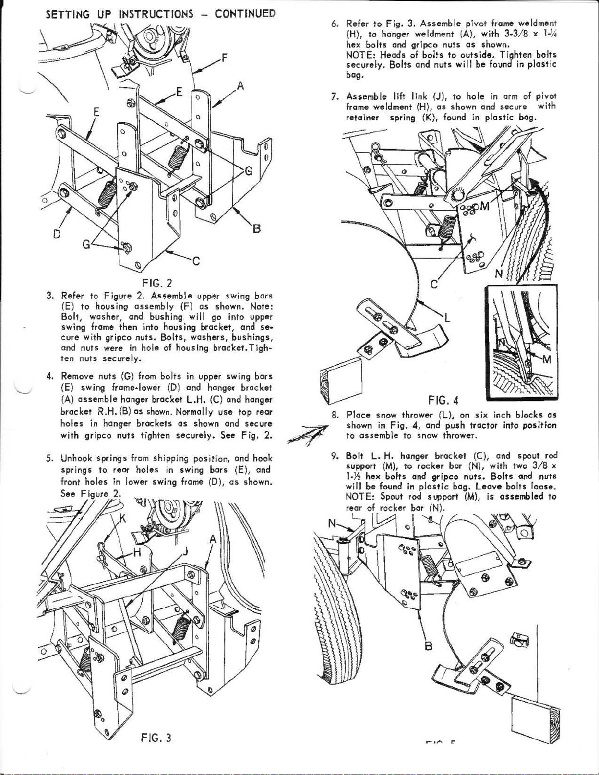
3.
Refer
(E)
Bolt,
swing frame
cure
and
ten
to
Figure
to
housing
washer
with gripco
nuts
nuts
, and bushing will go into upper
then
were
securely.
-
CONTINUED
2.
Assemble
assembly
into housing bracket, and
nuts.
Bolts,
in
hole
of
upper swing
(F)
as
washers,
housing
shown. Note:
bracket.
bars
se•
bushings,
Tigh-
6. Refer
7.
to
Fig.
(H),
to
hanger we ldment {A), with
hex
bolts
and
NOTE: Heads of
securely.
bag.
Assemble
frame weldment (H),
re
ta
Bolts
lift link (J),
iner spring (K), found
3.
Assemble
gripco
bolts
and
nuts
nuts
as
pivot
as
to
outs
will
to
hole
shown a
frame weldmer.t
3-3/8 x 1-
shown.
ide. T ighten
be
found in
in
arm of pivot
nd
secure
in plastic
14
bolts
plastic
with
bag.
4. Remove
{E) swing frame• lower {D) and hanger
(
A)
bracket
holes
with
5. Unhook
springs
front
See
nuts
assemble
R.H.
in hanger
gripco
springs
to
holes
Figure
(G)
from
bolts
in upper swing
hanger bracket L.H. (C)
(B)
as
shown. Normally
brackets
nuts
tighten
from
reor
holes
in lower swing frame (D),
2.
as
securely.
shipping
in
swing bars (E),
shown and
position, and hook
and
use
See
bracket
top
Fig.
as
bars
hanger
rear
secure
2.
and
shown.
8.
Place
shown
to
9.
Bolt
support
1·~
wi
NOTE: Spout rod
rear of rocker bar (N).
snow thrower (L), on
in
Fig.
assemble
L.
hex
I I
be
to
H. hanger
(M),
to rocker
bolts
found
in
L n
FIG. 4
4,
and
push tractor into
snow thrower.
brocket
bar
and
gripco
plastic
bog.
s~port
six
inch
blocks
position
(C), and spout rod
(N), with two
nuts.
Bolts
Leave bolts loose.
(M),
is
assembled
3/8
and nuts
as
x
to
FIG. 3

PARTS
IDENTIFICATION
(
PIVOT
LIFT
LEVER
FRAME
WELDMENT)
The
snow
ed for
have
been
It is
suggested
operate
key
A
When
R.H.
the
snow thrower
thrower
shipping
included in a
your unit .
letter
in
(right hand)
has
been
purposes.
that
this
the
following
or
or
direction
shipped
All
plastic
manual furnished with
L.H.
from
ports
such
bag.
paragraph
(left
hand}
of
travel.
the
as
refers
is
factory
nuts,
to
used
partially
washers,
the
unit
a key
it should
assembled.
bolts,
be
read
letter
be
understood
The
etc.
necessary
in
its
in
on adjoining
opera
ting
entirety
illustration.
to
mean from a
DEFLECTOR
IMPELLER
controls
to
complete
before
attempting
position
ASSEMBLY
HOUSING
ASSEMBL
ASSEMBLY
were left
assembly
unossemblof
to
assemble
behind and facing
the
Y
unit
or
Drain oil from
Wheel
weights,
<JI
...
1. Remove snow thrower from
wires.
2.
Refer
grease
of
deflector
shown.
o.ssembly with 3
bolts, lo<:k
ghten
T i
Important: Make sure
shown
front
and
clip
engine
and t ire
to
Fig.
or
equivalent}
Attach
nuts
turn
first
crankcase
chains
1. Apply
flange
deflector
deflector clip s
washers
securely.
deflector
. Rotate
of
tractor
added
carton
grease
to
upper and lower pa rt
on
housing
assembly
and hex nuts
clips
are positioned as
to
side
deflector
to
, and
(pressure
assembly
six
and assemble
assembly so
rear
to
Y.i
as
end
wheels
cut
housing
x
!-2
hex
shown.
all
gun
that deflector faces forward ond assemble remaining two
Make
on
sure
housing.
clips
.
deflector
assembly rotates
freely
refill
as
with SAE
will
greatly
lOW
Motor oil for
improve
the
performance
easier
starting
of
the
in cold
snow
weather.
thrower.
C:
If"
1
 Loading...