

Page 1
S__A/_S
OWNER'S
MANUAL
MODEL NO,
917,242440
£RIIFT$ I:IN+'
Caution:
Read and follow
all Safety Rules
and Instructions
Before Operating
This Equipment
Sears, Roebuck and Co., Chicago, IL 60684 U.S.A.
ELECTRIC LIFT
ACTUATOR KIT
for GARDEN TRACTORS
• Assembly
• Operation
• Customer
Responsibilities
• Repair Parts
Page 2
Safe Operation Practices for Ride-On Mowers
SAFETY RULES
IMPORTANT: THIS CUTTING MACHINE IS CAPABLE OF AMPUTATING HANDS AND FEET AND THROWING
OBJECTS. FAILURE TO OBSERVE THE FOLLOWING SAFETY INSTRUCTIONS COULD RESULT IN SERIOUS
INJURY OR DEATH.
I. GENERAL OPERATION
• Read, understand, and follow all instructionsin the manual
and on the machine before starting.
• Only allow responsible adults, who are familiar with the
instructions,to operate the machine.
• Cleartheareaofobjeotesuch as recks, toys,wire, etc., which
could be picked up andthrown by the blade.
• Be surethe area is clear of otherpeople beforemowing.Stop
machineif anyone enters the area.
• Never carrypassengers.
• Donotmow inreverse unlessabsolutelynecessary. Always
lookdown and behind before and whilebacking.
• Be aware of the mower dischargedirectionand do not point
it at anyone. Do notoperate the mower without either the
entire grass catcher or the guard in place.
• Slow down before turning.
• Never leave a runningmachineunattended. Alwaysturnoff
blades, set parking brake, stop engine, and remove keys
before dismounting.
• Turn off bladeswhen notmowing.
• Stop engine before removing grass catcher or unclogging
chute.
• Mow only in daylightor good artificiallight.
• Do not operate the machine while under the influence of
alcoholordrugs.
• Watch for trafficwhen operatingnear orcrossingroadways.
• Use extracarewhen loading or unloadingthe machineintoa
trailer or truck.
I1. SLOPE OPERATION
Slopes are a major factor related to loss-of-controland tipover
accidents,whichcan result in severe injury or death. All slopes
requireextracaution. If youcannotbackupthe slopeor ifyoufeel
uneasyon it, do not mow it.
DO:
• Mow upand downslopes, not across.
• Remove obstaclessuch as rocks,tree limbs, etc.
• Watch for holes, ruts, or bumps. Uneven terrain could
overturnthe machine. Tallgrass can hide obstacles.
• Use slowspeed. Choose a low gear sothatyouwillnot have
tostop or shiftwhile on the slope.
• Followthemanufactureer'srecommendations forwheel weights
or counterweightsto improvestability.
• Use extra care with grass catchers or other attachments.
These can change the stabilityof the machine.
• Keep all movement on the slopes slow and gradual. Do not
make sudden changes inspeed ordirection.
• Avoid startingor stoppingon a slope. If tires lose traction,
disengagethe blades and proceed slowly straightdown the
slope.
DO NOT:
• Donot turnonslopes unlessnecessary,andthen, turnslowly
and gradually downhill,if possible.
• Do not mow near drop-offs, ditches,or embankments. The
mowercouldsuddenlyrum overif a wheel isover the edgeof
a cliff or ditch,or if an edge cavesin.
• Do not mow on wet grass. Reduced traction could cause
sliding.
• Donottrytostabilizethemachinebyputtingyourfootonthe
ground.
• Do not use grasscatcher on steep slopes.
IlL CHILDREN
Tragic accidents can occur if the operator is not alert to the
presenceof children. Childrenare oftenattracted to the machine
andthe mowingactivity. Neverassume that children willremain
where youlast sawthem.
• Keepchildrenoutofthemowingarea andunderthe watchful
care of anotherresponsible adult.
• Be alert and turn machine off ifchildren enter the area.
• Before and when backing,look behind and down for small
children.
• Never carry children. They may fall off and be seriously
injuredor interferewiththe safe machineoperation.
• Never allow childrento operate the machine.
• Use extra care when approaching blind corners, shrubs,
trees, or otherobjectsthat may obscurevision.
IV. SERVICE
• Use extra care in handling gasoline and other fuels. They
are flammable and vapors are explosive.
Use only an approved container.
Never remove gas cap or add fuel with the engine
running. Allowengineto coolbefore refueling. Do not
smoke.
Never refuel the machine indoors.
Never storethe machine orfuel container insidewhere
there is an openflame, such as a water heater.
• Never run a machine inside a closedarea.
• Keepnutsandbolts,especiallyblade attachment bolts,tight
and keep equipment in goodcondition.
• Never tamper with safety devices. Check their proper
operationregulady.
• Keepmachinefree of grass,leaves, orotherdebris build-up.
Clean. oil or fuel spillage. Allow machine to cool before
storing.
• Stop and inspect the equipment if you strike an object.
Repair, if necessary, before restarting.
• Never make adjustmentsorrepairswiththe engine running.
• Grass catcher components are subject to wear, damage,
and deterioration,whichcould exposemovingparts or allow
objects to be thrown. Frequently check components and
replacewithmanufacturer'srecommendedparts,when nec-
essary.
• Mower blades are sharp andcan cut. Wrap the blade(s) or
wear gloves, and use extra caution whenservicing them.
• Check brake operation frequently. Adjust and service as
required.
Look for this symbol to point out impor-
tant safety precautions. It means
CAUTION!!! BECOME ALERT!!! YOUR
SAFETY IS INVOLVED.
CAUTION: Always disconnect spark
plug wireand place wire where itcannot
&
contact spark plug in order to prevent
accidental starting when setting up,
transporting, adjusting or making
repairs.
2
Page 3
CONGRATULATIONS on yourpurchase of a Sears Elec-
tric Lift Actuator Kit. It has been designed, engineered
and manufactured to give you thebestpossibledependa-
bilityand performance.
Should you experience any problemsyou cannot easily
remedy, please contact yournearest Sears Service Cen-
ter/Department. We have competent,well trainedtechni-
ciansand the proper toolsto serviceor repairthisunit.
Please read and retain thismanual. The instructionswill
enable you to assemble and maintain your Lift Kit prop-
erly.Always observe the "SAFETY RULES".
MODEL
NUMBER 917.242440
SERIAL
NUMBER
DATE OF
PURCHASE
THE MODEL AND SERIAL NUMBERS WILL BE
FOUND ON A DECAL LOCATED IN THE BAG
OF PARTS. ATTACH DECAL TO YOUR TRAC-
TOR FOR FUTURE REFERENCE.
YOU SHOULD RECORD BOTH SERIAL NUMBER
AND DATE OF PURCHASE AND KEEP IN A SAFE
PLACE FOR FUTURE REFERENCE.
CUSTOMER RESPONSIBILITIES
• Read and observe the safety rules.
• Follow a regular schedule in maintaining, caring for
and usingyourElectricliftkit.
• Follow the instructionsunder "Operation" and "Cus-
tomer Responsibilities"sectionsof thisOwner's Manual.
LIMITED ONE YEAR WARRANTY ON
CRAFTSMAN ATTACHMENTS
Forone year from thedate of purchase, when thiselectric lift attachmentis maintainedaccording totheoperating and
maintenance instructionsintheowner'smanual, Searswillrepairfree ofchargeanydefectin materialorworkmanship.
Thiswarranty does notcover:
• Expendable itemswhich becomewornduring normal use.
• Repairs necessarybecause of operatorabuse or negligence,includingthefailure to maintainthe equipment
accordingto instructionscontainedinthe owner's manual.
• Attachments used for commercialor rentalpurposes.
WARRANTY SERVICE ISAVAILABLE BY RETURNING THE CRAFTSMAN ELECTRIC LIFT KITTO THE NEAREST
SEARS SERVICE CENTER/DEPARTMENT INTHE UNITED STATES. THIS WARRANTY APPLIES ONLY WHILE
THIS PRODUCT IS IN USE IN THE UNITED STATES.
This warranty gives you specific legal rights, and you may also have other rights which vary from state to state.
SEARS, ROEBUCK AND CO., D/817 WA, HOFFMAN ESTATES, ILLINOIS. 60179
TABLE OF CONTENTS
SAFETY RULES ............................................................ 2
WARRANTY ................................................................... 3
PARTS ORDERING/SERVICE ..................................... 3
CARTON CONTENTS ............................................... 4-6
COMMON SET-UP ........................................................ 7
GEAR DRIVE REAR ASSEMBLY ................................. 8
HYDRO REAR ASSEMBLY .......................................... 9
ASSEMBLY TO VERT. ENGINE GT ...................... 10-13
ASSEMBLY TO HORZ. ENGINE GT .......................... 14
ELECTRICAL ASSEMBLY ..................................... 15-16
OPERATION ................................................................ 17
CUSTOMER RESPONSIBILITIES .............................. 17
REPAIR PARTS ..................................................... 18-22
3
Page 4
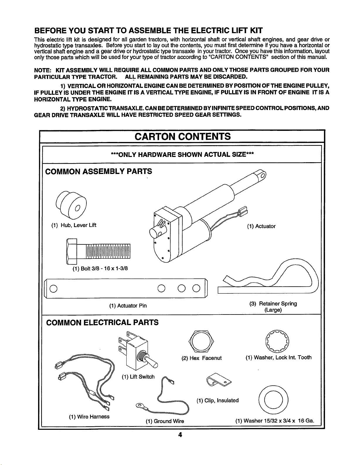
BEFORE YOU START TO ASSEMBLE THE ELECTRIC LIFT KIT
This electric lift kit is designed for all garden tractors, with horizontalshaft or vertical shaft engines, and gear drive or
hydrostatic type transaxles. Before you start to lay out the contents, you must first determine if you have a horizontal or
vertical shaft engine and a gear drive or hydrostatic type transaxle inyour tractor. Once you have this information, layout
only those parts which will be used for your type of tractor according to "CARTON CONTENTS" section of this manual.
NOTE: KIT ASSEMBLY WILL REQUIRE ALL COMMON PARTS AND ONLY THOSE PARTS GROUPED FOR YOUR
PARTICULAR TYPE TRACTOR. ALL REMAINING PARTS MAY BE DISCARDED.
1) VERTICAL OR HORIZONTAL ENGINE CAN BE DETERMINED BY POSITION OF THE ENGINE PULLEY,
IF PULLEY IS UNDER THE ENGINE IT IS A VERTICAL TYPE ENGINE, IF PULLEY IS IN FRONT OF ENGINE IT IS A
HORIZONTAL TYPE ENGINE.
2) HYDROSTATIC TRANSAXLE. CAN BE DETERMINED BYINFINITE SPEED CONTROL POSITIONS, AND
GEAR DRIVE TRANSAXLE WILL HAVE RESTRICTED SPEED GEAR SE'n'INGS.
CARTON CONTENTS
***ONLY HARDWARE SHOWN ACTUAL SIZE***
COMMON ASSEMBLY PARTS
(1) Hub, Lever Lift
(1) Bolt 3/8 - 16 x 1-3/8
0 0 O0 I
(1) Actuator Pin
COMMON ELECTRICAL PARTS
O
(2) Hex Facenut
(1) Actuator
(3) RetainerSpring
(Large)
Q
(1) Washer, LockInt.Tooth
(1) Wire Harness
(1) Lift_
(1) GroundWire
4
(1) Clip, Insulated
(1) Washer 15/32 x 3/4 x 16 Ga.
Page 5
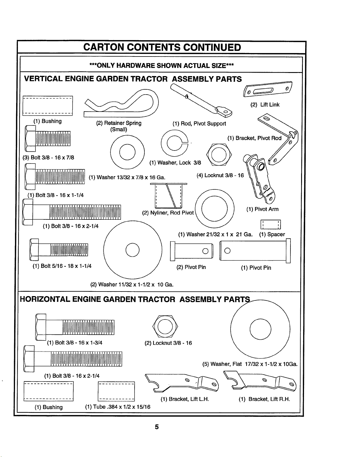
CARTON CONTENTS CONTINUED
***ONLY HARDWARE SHOWN ACTUAL SIZE***
VERTICAL ENGINE GARDEN TRACTOR ASSEMBLY PARTS
i_ j))-_ _ (2) LiftLink
(1) Bushing (2) RetainerSpring (1) Rod,Pivot Support _.._
(Small)
(1) Bracket,
(1) Washer 13/32 x 7/8 x 16Ga. (4) Locknut 3/8 - 1
I I
(1) Bolt318- 16 x 1-1/4 1 ',
I I
I I
(2) Nyliner, Rod Pivot (1) Pivot Arm
P_vot_
(1) Bolt 3/8 - 16x 2-1/4
(1) Washer21/32 x 1 x 21 Ga. (1) Spacer
(2) PivotPin (1) Pivot Pin
(2) Washer 11/32 x 1-1/2 x 10Ga.
HORIZONTAL ENGINE GARDEN TRACTOR ASSEMBLY
rIIIJIllflII
_(1) Bolt 3/8 - 16 x 1-3/4
(2) Locknut 3/8- 16
(5) Washer, Flat 17/32 x 1-1/2 x 10Ga.
(1) Bolt 3/8 - 16 x 2-1/4
(1) Bushing
1
(1) Tube .384 x 1/2 x 15/16
iI (1) Bracket, LiftL.H.
(1) Bracket, Lift R.H.
Page 6
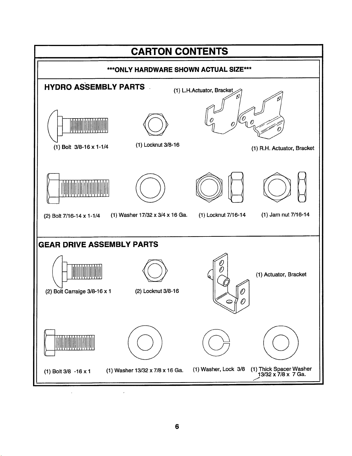
CARTON CONTENTS
***ONLY HARDWARE SHOWN ACTUAL SIZE***
HYDRO ASSEMBLY PARTS
G
(1) Bolt 3/8-16 x 1-1/4
(2) Bolt 7/16-14 x 1-1/4
GEAR DRIVE ASSEMBLY PARTS
(1) Washer 17/32 x 3/4 x 16 Ga. (1) Locknut7/16-14
(1) Locknut3/8-16
(1) LH.Actuator
(1) R.H. Actuator, Bracket
GD
(1) Jam nut7/16-14
(2) BoltCarraige 3/8-16 x I
(1) Bolt3/8 -16 x I
G
(2) Locknut3/8-16
(1) Washer 13/32 x 7/8 x 16 Ga.
6
0
,J
%
(1) Washer, Lock 3/8
(1) Actuator, Bracket
(1) Thick Spacer Washer
13/32 x 7/8 x 7 Ga.
/
Page 7
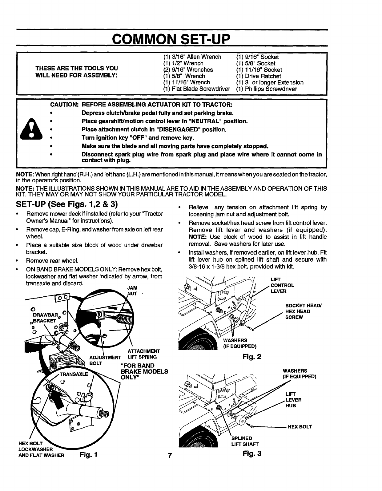
COMMON SET-UP
i
THESE ARE THE TOOLS YOU
WILL NEED FOR ASSEMBLY.
(1) 3/16" Allen Wrench
(1) 1/2" Wrench
(2) 9/16" Wrenches
(1) 5/8" Wrench
(1) 11/16" Wrench
(1) FiatBlade Screwdriver
(1) 9/16" Socket
(1) 5/8" Socket
(1) 11/16" Socket
(1) Drive Ratchet
(1) 3"or longerExtension
(1) PhillipsScrewdriver
CAUTION: BEFORE ASSEMBLING ACTUATOR KITTO TRACTOR:
Depress clutch/brake pedal fully and set parking brake.
Place gearshift/motion control lever in "NEUTRAL" position.
Place attachment clutch in "DISENGAGED" position.
Turn ignition key "OFF" and remove key.
Make sure the blade and all moving parts have completely stopped.
Disconnect spark plug wire from spark plug and place wire where it cannot come in
contact with plug.
NOTE: Whenright hand (R.H.) andleft hand (L.H.) arementionedinthis manual, itmeans when youare seated onthetractor,
in the operator'sposition.
NOTE: THE ILLUSTRATIONS SHOWN IN THIS MANUALARE TO AID INTHE ASSEMBLY AND OPERATION OF THIS
KIT. THEY MAY OR MAY NOT SHOW YOUR PARTICULAR TRACTOR MODEL.
SET-UP (See Figs. 1,2 & 3)
• Remove mower deck if installed(referto your "Tractor
Owner's Manual" for instructions).
• Remove cap, E-Ring, and washerfrom axle on left rear
wheel.
• Place a suitable size block of wood under drawbar
bracket.
• Remove rear wheel.
• ON BAND BRAKE MODELS ONLY: Remove hex bolt,
Iockwasher and flat washer indicated by arrow, from
transaxle and discard.
JAM
NUT
• Relieve any tension on attachment lift spring by
loosening jam nutand adjustmentbolt.
• Remove socket/hex head screw from lift control lever.
Remove lift lever and washers (if equipped).
NOTE: Use block of wood to assist in lift handle
removal. Save washers for later use.
• Install washers, if removed earlier, on lift lever ]]ub.Fit
lift lever hub on splined lift shaft and secure with
3/8-16 x 1-3/8 hex bolt, provided with kit.
LIFT
LEVER
O
DRAWBARo(
QBRACKET
Q
Q
HEX BOLT
LOCKWASHER
AND FLATWASHER
ATrACHMENT
LIFT SPRING
BOLT
"FOR BAND
BRAKE MODELS
ONLY"
Fig. 1 7
SOCKET HEAD/
HEX HEAD
SCREW
WASHERS
(IFEQUIPPED)
Fig. 2
WASHERS
(IF EQUIPPED)
LIFT
LEVER
HUB
HEX BOLT
SPLINED
LIFT SHAFT
Fig. 3
Page 8
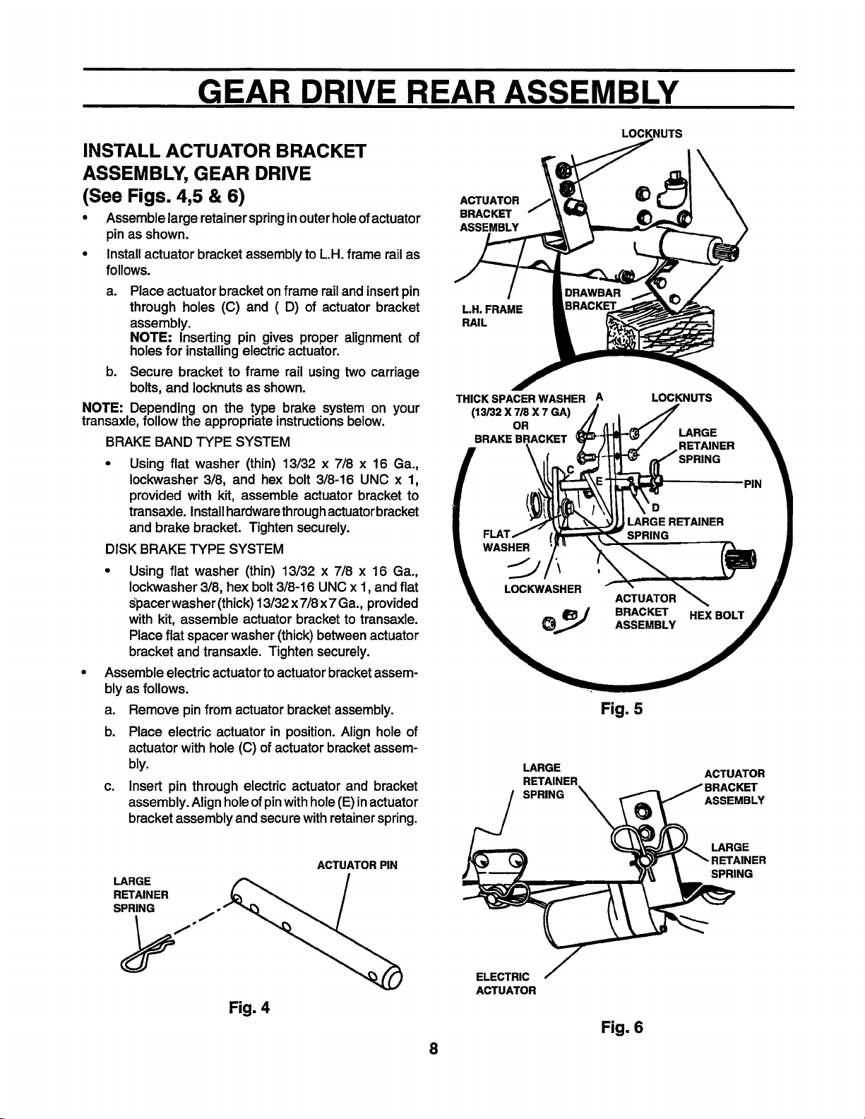
GEAR DRIVE REAR ASSEMBLY
INSTALL ACTUATOR BRACKET
ASSEMBLY, GEAR DRIVE
(See Figs. 4,5 & 6)
• Assemblelarge retainerspringinouterholeofactuator
pin as shown.
• Installactuatorbracket assemblytoLH. frame railas
follows.
a. Place actuator bracket on frame rail and insert pin
through holes (C) and (D) of actuator bracket
assembly.
NOTE: Inserting pin gives proper alignment of
holesfor installingelectric actuator.
b. Secure bracket to frame rail using two carriage
bolts,and Iocknutsas shown.
NOTE: Depending on the type brake system on your
transaxle, followthe appropriate instructionsbelow.
BRAKE BAND TYPE SYSTEM
• Using flat washer (thin) 13/32 x 7/8 x 16 Ga.,
Iockwasher 3/8, and hex bolt 3/8-16 UNC x 1,
provided with kit, assemble actuator bracket to
transaxle. Installhardwarethroughactuatorbracket
and brake bracket. Tighten securely.
DISK BRAKE TYPE SYSTEM
• Using flat washer (thin) 13/32 x 7/8 x 16 Ga.,
Iockwasher 3/8, hex bolt 3/8-16 UNC x 1, and flat
Spacerwasher (thick) 13/32 x 7/8x 7 Ga., provided
with kit, assemble actuator bracket to transaxle.
Place flat spacer washer (thick) between actuator
bracket and transaxle. Tighten securely.
Assemble electric actuator to actuator bracket assem-
bly as follows.
a. Remove pin from actuator bracket assembly.
b. Place electric actuator in position. Align hole of
actuator with hole (C) of actuator bracket assem-
bly.
c. Insert pin through electric actuator and bracket
assembly. Align holeof pinwith hole (E)in actuator
bracket assembly and secure with retainer spring.
LOCKNUTS
ACTUATOR
BRACKET
ASSEMBLY
L.H. FRAME
RAIL
THICK SPACER WASHER A LOCKNUTS
(13/32 X 7/8 X 7 GA)
OR
BRAKE BRACKET
_D PIN
m ;LARGE RETAINER II
I SPRING |
\w,s I
_,, _J BRACKET HEX BOLT _ r
Fig. 5
LARGE ACTUATOR
RETAINER
SPRING ASSEMBLY
tKET
LARGE
RETAINER
SPRING
LARGE
ACTUATOR PIN
SPRING
J
ELECTRIC
ACTUATOR
Fig. 4
Fig. 6
8
Page 9

HYDRO REAR ASSEMBLY
INSTALL ACTUATOR BRACKET
ASSEMBLY, HYDRO (See Fig. 7)
• Remove upper hex bolt securingtransaxle bracketto
LH frame rail,as indicatedby arrow.
• Fitleftandrightactuatorbracketstogether,bentbracket
to inside. Slide actuatorbracketassemblyup against
insideof LH frame rail, as shown.
• Assemble 3/8-16 x 1carriageboltthroughLHframe rail
and uppercorner holes of actuatorbracketassembly,
as shown. Hand tighten3/8-16 Iocknuton bolt.
• Insert7/16-14 x1-1/4 hexboltfrom insidetractorframe
railsthroughRH actuatorbracket,drawbar,LH frame
rail and transaxle bracket as shown. Hand tighten
Iocknuton hex bolt
• While holding jamnut on inside of actuator bracket
assembly, insert remaining 7/16-14 x 1-1/4 hex bolt
from outsidethroughtransaxle bracket, LH frame rail
and actuatorbracketassemblyandthreadintojamnut,
as shown.
• Tighten allhardware securely.
HEX BOLT
JAMNUT (THIN) INSIDE)
LH. FRAME
RAIL
ASSEMBLE ELECTRIC ACTUATOR
TO BRACKETS, HYDRO
(See Figs. 8 & 9)
• Assemblelargeretainerspringinouterhole ofactuator
pinas shown.
NOTE: useend of actuator pinwith only onehole.
• Place actuator inplace and align hole inactuatorwith
holesinactuator bracket assembly.
• Insertactuatorpin through holes in bracket assembly,
actuatorand flat washer. Retain with large retainer
springat innermosthole locationas shown.
ACTUATOR PIN_
Fig. 8
ELECTRIC
ACTUATOR
FLATWASHER
LARGE
RETAINER
SPRING
L.H. FRAME
RAIL
R.i
ACTUATOR
BRACKET
SKID BRACKET
R.H. ACTUATOR
BRACKET"
©
L.H. ACTUATOR
BRACKEI
_EMOVE HEX
BOLT AND
DISCARD
.TRANSAXLE
BRACKET
ACTUATOR PIN
ELECTRIC
ACTUATOR
LARGE
RETAINER
SPRING
FLATWASHER
ACTUATOR PIN
ACTUATOR
BRACKET
LARGE
RETAINER
SPRING
Fig. 7 9 Fig. 9
Page 10

ASSEMBLY FOR VERTICAL ENGINE MODELS
LIFT KIT ASSEMBLY TO GT
w/VERTICAL ENGINE
(See Figs. 10 thru 16)
PREPARATION
• Remove height indicatoron LH side of tractor frame.
Save all partsexcept hexboltfor reassembly.
FLAT
WASHER
HEX BOLT
SNAP-OUT
COVER
HEIGHT
INDICATOR 7 -
LOCK
WASHER
FLAT
WASHER
Fig. 10
ASSEMBLE PIVOT ARM ASSEMBLY
• Assemble bothliftlinks betweensides of pivot arm as
shown. Securewithlargerpivot pin and small retainer
spring.
NOTE: Slots inliftlinksare not centered andmust be
assembledcorrectly.To assemble holdpivotarmwith
bent end towards you and downwards. Positionlift
linkssoslotisto leftand narrowedge isat bottom(see
inset)
• Place spacerbetweenthe two linksand insertsmaller
pivotpin. Secure withsmall retainerspring.
• Installtwo nylinersintopivot bracket as shown.
NYLINER
PIVOT ARM
NYLINER
LIFT LINKS
Slide21/32 x 1 x 21 Ga. washeronto pivot rodsupport
up to nibs. Set aside for later use.
NIBS
PIVOT ROD
SUPPORT
21/32 X 1 X 21 GA.
WASHER
Fig. 11
SMALL
RETAINER
SPRINGS
SPACER
BE SURE SLOT IS
TO LEFT AND
NARROW EDGE IS
TO BOI-rOM
BENT END OF
PIVOT ARM
0
LARGER
PIVOT PIN
SMALLER
PIVOT PIN
INSET
10
Fig. 12
Page 11

ASSEMBLY FOR VERTICAL ENGINE MODELS
ASSEMBLE PIVOT ROD BRACKET
Installpivot rodbracketto insideof R.H. frame fail'using
two hex bolts3/8-16 x 7/8 and two 3/8-16 Iocknuts.
1. Be sure parking brake isengaged. Positionpivot
rodbracket to insideof R.H. frame railand install
one hex boltthroughuppermountinghole._Jnstall
Iocknuton hex bolttooutsideof frame rail.
2. Disengage parking brake, and installremaining
hex boltand Iocknutas shown.
Tightenhardwaresecurely. Besureto engage parking
brake after pivot rod bracket is installed.
VIEW FROM UNDER TRACTOR
3/8-16 LOCKNUT
1
PARKING BRAKE
DISENGAGED
ROD BRACKET
3/8-16 X 718
HEX BOLT
PIVOT ROD BRACKET
318-16 X 718
BOLT
UPPER
.MOUNTING
HOLE
_,RIGHT HAND
FRAME RAIL
PARKING BRAKE
ENGAGED
Fig. 13
11
RIGHT HAND
FRAME RAIL
Page 12

ASSEMBLY FOR VERTICAL ENGINE MODELS
INSTALL PIVOT ARM ASSEMBLY
Raise link assembly until nylinersare in4inewithhole
inLH sideoftractorframe. Insertpivotrodsupportwith
washerthroughnylinersinpivotarm,asshown.Loosely
assembly to hex bolt 3/8-16 x 718 and lock washer
throughholein LH side offrame. Do nottightenat this
time.
Assembleflattenedend ofpivot rodsupportto under-
side of pivot rodbracket usinghex bolt3/8-16 x 1-1/4,
flat washer and Iocknut and tighten securely. Now
tighten previouslyassembled 3/8-16 x 7/8 hexbolt.
318-16 X 718 LOCK NYUNERS AND
HEX BOLT WASHER PIVOT ARM FLAT
3/8-16 X 1-1/4 WASHER
HEX BOLT
VIEW FROM UNDER TRACTOR
PIVOT ROD BRACKET
Fig. 14
12
3/8-16 X 7/8 LOCK
HEX BOLT
HOLE IN LH SIDE
OF TRACTOR
FLAT
NYLINERS AND
PIVOT ARM
ASSEMBLY
318-16 LOCKNUT PIVOT ROD
SUPPORT
Page 13

ASSEMBLY FOR VERTICAL ENGINE MODELS
ATTACH ACTUATOR & LIFT LINKS
1 Insertactuatorarm and bushingbetweenpivotarmsas
shown.Secure with3/8-16 x2-1/4 hexboltandIocknut.
NOTE: Be sure that bolt is assembled in direction
shown.
2 Positionone lift linkon each sideofthe liftshaftbracket
as shown. Insert smaller pivot pin and secure with
small retainer spring.
LIFT
SHAFT
BRACKET
SMALL SMALLER
RETAINER PIVOT PIN
SPRING _ LIFT LINK
HEX BOLT
LIFT UNK
(ONE ON EACH SIDE OF
LIFT SHAFT BRACI_'T)
(ONE ON EACH SIDE OF
LIFT SHAFT BRACKET)
BRACKET
REASSEMBLE HEIGHT INDICATOR
Reassembleheightindicatorpreviouslyremovedadd-
ingtwospacerwashersand replacinghexboltwiththe
5/16-18 x 1-1/4 hexboltprovidedwiththis kit. Ensure
height indicatoris showingcorrect position of deck.
This may be adjustedafter final assembly of deck by
loosening hex bolt and moving height indicator to
correctpositionin relationto deck, retightenhex bolt
and replace snap-out cover. Assemble all parts in
order shown.
FLAT
WASHER
LOCK
WASHER
NEW HEX BOLT ADD SPACER
SNAP-OUT
SMALL Fig. 16
RETAINER
SPRING
HEIGHT
INDICATOR
FLAT
WASHER
ACTUATOR
ARM
Fig. 15
13
2
1
LOCKNUT
VIEW FROM
UNDER TRACTOR
PIVOT PIN
HEX BOLT
PIVOT ARMS
ACTUATOR
ARM
BUSHING
Page 14

ASSEMBLY FOR HORIZONTAL ENGINE MODELS
LIFT KIT ASSEMBLY TO GT
w/HORiZONTAL ENGINE
(See Figs. 17 and 18)
• Assemble L.H. and R.H. lift brackets to lift shaft
assembly arm using hex bolt 3/8-16 x 1-3/4, five
washers,one tube, andone Iocknutas shown.
NOTE: When assembling lift brackets, make sure top
of L.H. and R.H. brackets are positionedon lift shaft
assemblyarm (offset to the right).
a. Inserthex boltthrough R.H. liftbracket.
b. Place tube and two washerson bolt.
c. Enter bolt throughhole of liftshaftassembly arm.
d. Placethreewashers, L.H.liftbracket, and Iocknut
on boltand tighten securely.
NOTE: The five washers are not used when assembling
lift mechanismto sleeve hitch. See your sleeve hitch
manualwhen installingthis electricliftactuator ontractors
soequipped.
L.H. LIFT
BRACKET
BRACKET
LIFT
SHAFT
ASSEMBLY
ARM
.IFT
BRACKET
R.H. LIFT
BRACKET I
Assemble extension arm of electric actuator to L.H.
and R.H. lift brackets using hex bolt 3/8-16 x 2-1/4,
bushing,and Iocknut.
a. Insertbushingin hole of actuatorarm.
b. Position actuator arm between L.H. and R.H. lift
brackets.
c. Insert hex bolt through hole (B) of L.H. lift bracket
goingthroughactuatorarm and R.H. liftbracket.
d. Place Iocknuton boltand tightensecurely.
LOCK'NUT
MALE
RS
Fig. 17
LIFT
HARNESS
TUBE_
R.H. LIFT
BRACKET
ELECTRIC
ACTUATOR
LH. LIFT
BRACKET
14 Fig. 18
Page 15

COMMON ELECTRICAL ASSEMBLY
WIRING ASSEMBLY FOR ALL
TRACTORS
(See Figs. 19 thru 24)
I_ BEFORE WORKING ON ELECTRICAL
Locatethe blackplasticplugin upperrightor left side
of dash. Remove plug and assemble lift switch.
NOTE: Pluglocation may be differentthanshown.
a. Secure one nut to liftswitchas shown.
b. Enter lift switch in dash hole (with Keyway down)
Connect ground wire (black single wire) to lift switch.
a. Viewing liftswitch from under hood, connect black
b. Connect opposite end (eyelet) under the right or
SYSTEM DISCONNECT BATrERY. RE-
CONNECT BATrERY WHEN FINISHED.
from underside of dash, placing flat washer, inter-
nal tooth Iockwasher and nutoverthreaded area of
lift switch. Tighten nut securely.
wire to upper left hand side terminal of switch.
left upper rear battery support nut. Support nut
(indicated byarrow) located on insideof right or left
side panel.
LIFT
SWITCH
BLACK
{GROUND)
WIRE
RIGHT OR LEFT UPPER
REAR SUPPORT BOLT
Fig. 20
RIGHT OR
PANEL
Fig. 19
PLUG
Fig. 21
15
Page 16

COMMON ELECTRICAL ASSEMBLY
• Connect lifthamess to electricactuator.
a. Connect male connector of harness to female
connector of electric actuator.
• Viewing lift switch from under hood connect lift har-
ness to lift switch.
a. Connect yellow wire of lift harness to lower right
terminal of lift switch.
b. Connect double red wire of lift harness to lower
left terminal of lift switch.
c. Connect single red wire to upper right terminal.
• Secure wiring harness.
a. Remove Iocknut (underside of tractor) on L.H.
saddle bolt.
b. Install insulated clip over bolt as shown. Replace
Iocknut and tighten securely.
c. Insert wiring harness in clip as shown.
• Raise hood, insert female connector of lift harness
into male connector of tractor harness.
• Ensure wire routing does not allow wires to rest on
sharp edges or near moving parts.
SHIFT L.H. DASH
GATE BOLT
COVER
WIRING
HARNESS
INSULATED
BLACK
(GROUND)
WIRE
(TOP)
LOWER
DOUBLE
RED WlRE
Fig. 22
LIFT
VIEWED FROM
BEHIND DASH
SINGLE
RED WIRE
YELLOW
WIRE
Fig. 23
FEMALE CONNECTOR
HARNESS)
MALE CONNECTOR
_RACTOR HARNESS)
DASH
(CUTAWA_
O
VIEWED FROM
LEFT SIDE OF
TRACTOR
Fig. 24
REASSEMBLE TRACTOR
• Reinstall rear wheel and mower deck, if removed
earlier.
• Remove wood block.
• Reconnect spark plug wire.
• Retighten liftassist spring bolt.
16
Page 17

OPERATION
Make sureall Boltsand Nuts are tight, Retainer Springs
are secure.
READ THE "RULES FOR SAFE OP-
ERATION" CAREFULLY BEFORE OP-
ERATING YOUR ELECTRIC ACTUA-
TOR.
.
Ignition Switch must be "ON" to operate Electric
Actuator.
2.
AfteryouinstallLiftSwitchfollow markingsalreadyon
dashboard.
.
Ifyou hear a ratcheting sound, you know you are fully
raised or fully lowered. Release Switch promptly after
ratchetingbegins.
GROU ND WHEN TURNING CORNERS,
LIFT ATTACHMENT OUT OF THE
REVERSING OR TRANSPORTING.
THE ELECTRIC ACTUATOR IS
EQUIPPED WITH AN OVERLOAD CIR-
CUIT THAT WILL TRIP WHEN OVER-
LOADED.
UNIT WILL AUTOMATICALLY RESET
AFTER 10 SECONDS.
J
J
CUSTOMER RESPONSABILITIES
LUBRICATION
.
The Electric Actuator is lubricated for normal life. If
Actuator is disassembled for repair, upon reassembly
lubricate with high performance extreme pressure
lubricating grease.
2.
Apply a light coat of grease to threaded areas and
Pivot Points.
17
Page 18

REPAIR PARTS
ELECTRIC ACTUATOR-- MODEL NUMBER 917.242440
GEAR DRIVE, HORIZONTAL ENGINE TYPE TRACTOR
3
31
47
14
7
2
8
7
9
2O
2O
18
Page 19

REPAIR PARTS
ELECTRIC ACTUATOR- - MODEL NUMBER 917.242440
GEAR DRIVE, VERTICAL ENGINE TYPE TRACTOR
13
15
14
2
12
31
34
36 / _-/_t-JI "1_I_,_I 6
37 10_'@ /
14
24
26
19
Page 20

REPAIR PARTS
ELECTRIC ACTUATOR- - MODEL NUMBER 917.242440
HYDROSTATIC DRIVE, VERTICAL ENGINE TYPE TRACTOR
14
31
42
43
35 44
39
4O
20
12
14
2O
19
2O
20
Page 21

REPAIR PARTS
ELECTRIC ACTUATOR- - MODEL NUMBER 917.242440
KEY PART
NO. NO.
1 4171R
2 74520636
3 74520628
4 5948J
5 74760622
6 19131407
7 19172410
8 5949J
9 5947J
10 10040600
11 74760620
12 5950J
13 74760614
14 4939M
15 139276
16 138908
17 19211621
18 138914
19 138948
20 73800600
21 19131416
22 138912
23 138905
24 138947
25 138909
26 127017X
27 8984R
28 7320R
29 7319R
30 19151216
31 124371X
32 105624X
33 677A886
34 72270608
35 140877
36 4940M
37 74760616
38 9698R
39 74780720
40 73350700
41 73800700
42 72140620
43 140876
44 140875
45 19171216
46 74760520
47 19112410
DESCRIPTION
Clip, Insulated
Bolt, Hex 3/8-16 x 2-1/4 Grade 5
Bolt, Hex 3/8-16 x 1-3/4 Grade 5
Bracket, LiftL.H.
Bolt, Hex 3/8-16 x 1-3/8
Washer 13/32 x 7/8 x 7 Ga.
Washer 17/32 x 1-1/2 x 10 Ga.
Tube .384 x 1/2 x 15/16
Bracket,LiftR.H.
Washer, Lock
Bolt, Hex 3/8-16 x 1-1/4
Bushing .384 x 1/2 x 1-1/4
Bolt, Hex 3/8-16 x 7/8
Spring, Retainer
Nyliner
Arm, Pivot
Washer 21/32 x I x 21 Ga.
Rod, PivotSupport
Pin, Pivot
Locknut3/8-16
Washer 13/32 x 7/8 x 16 Ga.
Bracket,Pivot Rod
Link,Lift
Pin, Pivot
Spacer
Harness, LiftKit
Switch, Lift
Nut, Switch
Washer, LockInt.Tooth
Washer 15/32 x 3/4 x 16 Ga.
Electric,Actuator
Hub, LeverLift
Bracket,AssemblyActuator, Gear Drive
Bolt, Carriage 3/8-16 x 1
Pin, Actuator
Spring, Retainer
Bolt, Hex 3/8-16 x 1
Wire, Ground
Bolt,Hex 7/16-14 x 1-1/4
Jam Nut7/16-14
Locknut7/16-14
Carraige Bolt3/8-16 x 1-1/4
LH ActuatorBracket,Hydro
RH Actuator Bracket, Hydro
Washer 17/32 x 3/4 x 16 Ga.
Bolt, Hex 5/16-18 x 1-1/4
Washer 11/32 x 1-1/2 x 10 Ga.
21
Page 22

REPAIR PARTS
ELECTRIC ACTUATOR- - MODEL NUMBER 917.242440
J 3
s
2
4
7
8
9
/
I
10
f
KEY
NO.
2
3
4
5
6
7
\ /
\ 14
\
\
\
\
\ I
PART
NO.
1862J
1863J
8331J
1857J
1865J
1864J
677A149
13
\
\6
DESCRIPTION
Screw- SI. Fil. Hd. Mach. No. 10-
32 x 1-5/8
Lockwasher- No. 10
HousingCover
CoverGasket
Snap Ring
RetainingRing
SpringWasher (Use 3 or 4 as
req'd.)
22
KEY
NO.
8
9
10
11
12
13
14
\
\
\.
PART
NO.
674A281
1859J
1861J
673A218
1860J
1858J
12
DESCRIPTION
Pawl & RampWasher
Out put Gear
Motor - 12V
Connector Body Kit
Not Serviced Separately Order
complete actuator Part# 124371X
Thrust Washer
Intermediate Gear
Page 23

SERVICE NOTES
23
Page 24

OWNER'S
MANUAL
MODEL NO.
917.242440
[RRFT$ AN°
ELECTRIC LIFT
ACTUATOR KIT
for GARDEN TRACTORS
Each liftkit has itsown model number.
This liftkit when mountedto your tractorisnot visiblyaccessible. There-
fore, the model plate (included in parts bag) has convenient self-stick
adhesive for placement on tractor. Always mention the model number
when requesting service or repair parts.
IF YOU NEED
REPAIR SERVICE
OR PARTS:
FOR REPAIRSERVICE, CALL
THIS TOLL FREENUMBER:
1-800-4-REPAIR
(1-800-473-7247)
FOR REPLACEMENT PARTS
INFORMATIONAND
ORDERING, CALL THIS
TOLL FREE NUMBER:
1-800-FON-PART
(1-800-366-7278)
All parts listed herein may be ordered from any Sears, Roebuck and Co.
Service Center and most Retail Stores.
WHEN ORDERING REPAIR PARTS, ALWAYS GIVE THE FOLLOW-
ING INFORMATION:
• PRODUCT - ELECTRIC LIFT ACTUATOR KIT
• MODEL NUMBER -917.242440
• PART NUMBER
• PART DESCRIPTION
Your Sears merchandise has added value whenyou consider Sears has
service units nationwide staffed with Sears trained technicians.., profes-
sional technicians specifically trained to insure that we meet our pledge
to you, we service what we sell.
Sears, Roebuck and Co., Chicago, IL 60684 U.S.A.
142176 11.10.93 PRINTED IN U.S.A.
 Loading...