Page 1
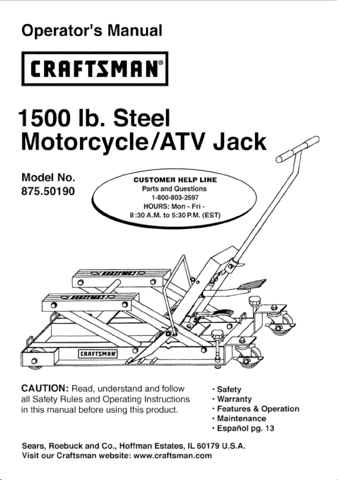
Operator's Manual
1
Model No,
CAUTION: R:ead, understand and follow
aH Safety Ruies and O#erating #sstructions
ir_ this manua_ before using this #_oduct,
Sears, Roebuck and Co,, Hoffman Estates, IL 60179 U,S.A,
V_s_t oer Craftsman webs_te: www.craftaman,eom
• Safety
- Warranty
• Features & Operation
• Maintenance
• Espa_o| pg, 13
Page 2
ONDYEAR FULL WARRANTY ON CRAFTSMAN PRODUCT
[f th_s Crsflsmar_ pf_uct fails @e to a defect in mater_a_ a_ wo_kme_ship ,_ thin one
yt_.a[ from _he date d pUrcha_a RETURN IT TO ANY SEARS STORE OR OTHER
CRA_SMAN OUTLET IN THE UN_ED STATES FOR FREE REPLACEMENT,
ff _¢s @aftsman prcyjuct is used _a_ comme_cia_i of re,tat purposes this war_a_ty
appk_s bf On_y 90 days f_om Be date d pu[chase.
This warranty _ves you s42ee}f_c le_ _ghte and yo_._ may alse have oc_e_ ' r_ghts
whirl vary from s_ate t9 s_ate
£_a_ R@_b_¢k aRd CO,. Dept 8t 7 WA Hoffma_ Estates _L 60179
SAVE THESE INSTRUCTIONS! ;READ ALL INSTRUCTIONS!
ZWARNWNG:]
* Fa}/_fe te comply with ebfma_ie_ h _his man,ual or to heed product _amk_g !abe_s
may result e persor_al sissy or property damage
. Sfu@_ a.ede_s_and a_d fe t_,, air 1he hs_ruetioes be_O_e opefa%g this device
, ONLY use iack De a _rd #ave_ s_dace tP_I iS capable d sap_xsrfl_'tg the veh c_e
, Lift o_ty on area5 d vehicle as sT, ecBed by the vehicle maeufacture_
, ALWAYS u_ tieodowe straps to secure the sehicb to the jack.
NEVER me_e vehid_ with jack if straps are no_ ie pb_._e ef secde.
* ALWAYS use the height bck bar wher_ the vehic#e is _aised te preve_l the
vehicb from dropp _g accidental y;
, ALWAYS b_e[ the vehicle to the bwes_ _ss_b/e jack p_itk)_ BEFORE
attempting to d@_ or mere it
"DO NOT make az_y alte_atlees te this Feduct
* the _a_ bebre each a_,
* DO NOT u_ }f bak_g flukJ andor bre_n_ beret c_a@ed of ether'¢4se dama_J
pass ale tiered
* Immediately afte_t raiat#g vehicle, ensure that Height Lock Bat is engage&
* ALWAYS _ar safe_y _@e_ _rat_ng ths predict.
iaek it could cause serie_s badly ieju_y_
Page 3
, Open the re/ease valve by pressing down on the re_ease peda_ (_
(see Fig. t and 2)
• Remove the oil fi_ plug__(see Fig i).
• Pump the foot peda_ (_ (see Fig I and 2) 6 to 8 times to release any
pressurized air that may be trapped in the oi_ reservoir (hydraulic system)
- Be sure oii leve_ is just be_ow the threads in the ot fi_i p_ug hole if oi_ needs
to be added fo_r_,_ the instructions on page 9.
• Replace and tighten oi_ fi_ plug.
This iack (see Figs_ 1 IA IB and 2) has specia_ builHn featu[es that make
it idea_ for pedorming minor repairs oil changes cleanups and more.
These features include:
, 1500_pound load capacity to lift most motor_cles and ATVs.
, A fasbaction hydraulic pump with toot pedal (J_see Fig2) for easy lifting
from 51/s to 17 inches above front of iack base Two adapter p/ares, sg/d
separate_/(see Fig. 1A) are availabieto allow lilting to 19 nches above
front d jack base.
- 3 position Height Lock Bar provides positive locking at three lift heights:
1t _4 in., t4 1/_ in. and 16 I/2 in (see Fg.1)_
iMPORTANT: Upon raising vehic[e_ the jack must IMMEDIATELY be locked
into one d the three lift heights.
* Precision controlled _oot release_(F g.2) for Iowedng the vehicle
, Can be used as a dolly to move your vehicle to a convenient location
for working or storage.
, T:Handie (Fig. 1 ) for added control when dotMng veh}cle into work ng or storage _a_ion.
, The jack a_so includes h*_o l_inch wide × 15 foot long ratchetihg tie-down
straps (see Rg 1B) to help secure the vehicte.
, The jack has adiustab_e locking screws and _ocking casters
to increase stability (see Fig°t ).
Page 4
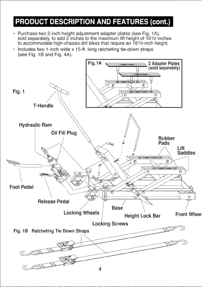
, Purchase two 2rich height adiustment adapter plates (see Fig. 1A),
sold separately, to add 2 inches to the maximum _ift height of i6V2 inches
to accommodate high-chassis di_ bikes that require an 18V24nch heighL
• _nc_udes two 1*inch wide x i 5-ff. _ong ratcheting tie_dowr_ straps
(see Fig. 1B and F]g_ 4A)_
Fig,IA
i_l.,< ....................................... _.i_ _ j ............ /so_di_..._p,_te_yt
Foot Pedal
Release P_al
Base
Locking Wheels Height Lock Bar
Locking Screws
Lift
Saddles
Page 5
............. _ ........................ _,_x_2""_'_"° .............................................. ,__ ........................ !_.}::}l
......... _; ................. _:}::::::X//:i: 2 :Ii:_:::ili
............... :_ ................. /_ M_'_ ,,_ _ A
(see _tg_)
P
Page 6
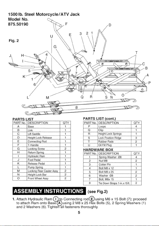
2. insert Foot Peda_ Arm @ into the sleeve of Hydraulic Ram _ and
secure wth M8 x 12 Hex Bolt (4)_
3, Attach Height Lock Re_ease @ to Height Lock Bar using 2 Spdng
Washers G8 (1)AND 2 Nuts M8 (2),
4, Attach T-Handle _to ConnectiRg Rod _ with Cotter Pin (3),
5. Make sure that ali connections are tightened thoroughly.
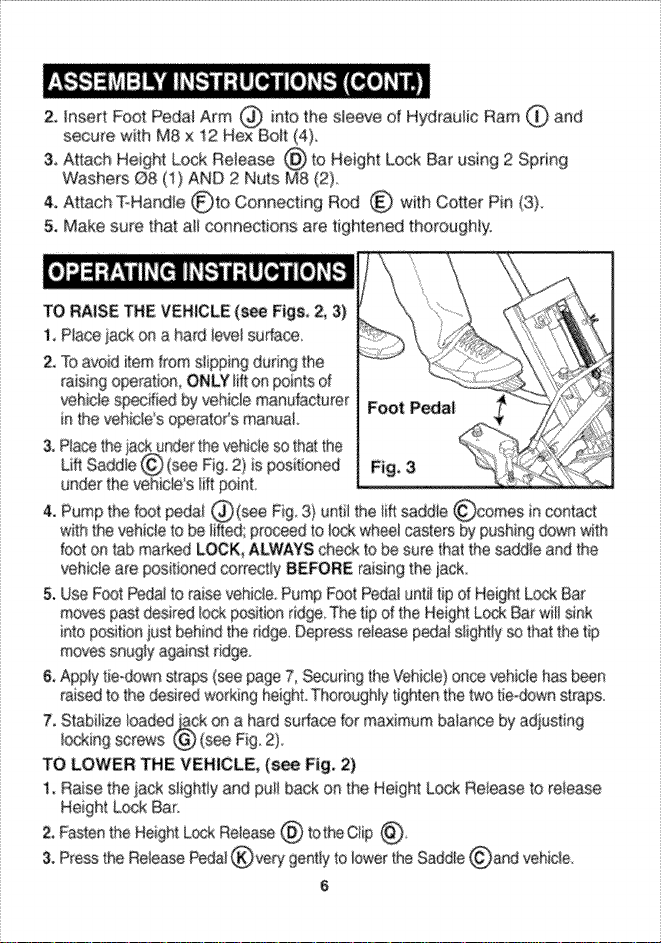
TO RAISE THE VEHICLE (see Figs 2_ 3)
1, P_ace _ck on a hard ievef surface
2. To a/'_id item from slipping du#ng tP_
_aising o_ration ONLY litton points d
vehicle ed by vehlcie manufacturer F_t Pedal
in the veh_sWs operatoCs manual
under the vehicle s lift point.
f@t on tab marked LOCK_ AL_YS @ec£ to _ sure #_at the _dd_e and the
vehicle are p@sit£_ed co_Tect_y BEFORE raising the }8_k
5, Use Fc_t Peda_ to raise vehicle, Pump Foot Peda} unti_ tip o_ Height L_;_ Bar
m_s past desired _c_k positbn ridge The tip of the Height Lock Bar wit! sink
ilto position just behind the ddge. Depress release peda_ s_ight_y so that #'_e tip
moves saugty a_inst _idge
& Apply t}e-down straps (see page 7, Secudng the '_,Lehicle) once _hic_e has been
raised to the desired working he_ht Thoroughly tighten the two tie-®wn straps.
7, Stabiiize _oaded on a hard surface for maximum balance by adjustin 9
_ocking screws
TO LOWER THE VEHICLE, (see Fig, 2)
1, Raise the iack s_ighfly and pull back on the Height L_sk Re_ease to release
2, Fasten the Height L_k Retease @ tothe Qip @_
3. Press the Relea_ Pedal _very gently to lower the Saddle _)and vehicle
6
Page 7
1_ | Tie-down straps wi!l become I_se and vehiste wilt
I
be releas_i upon lowering the vehicle
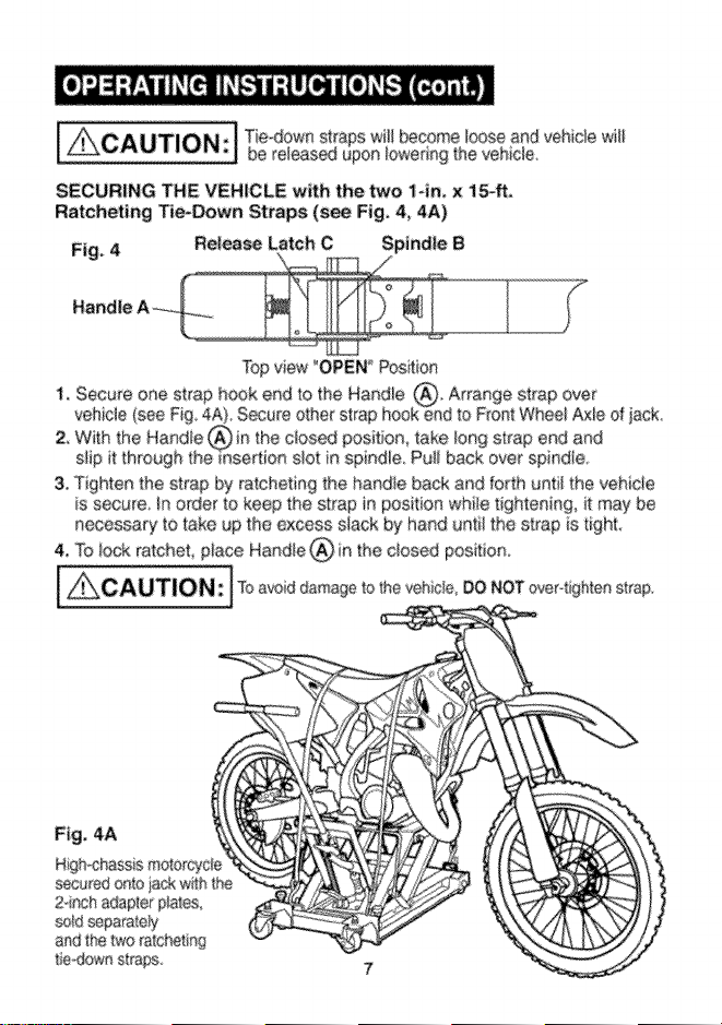
SECURING THE VEHICLE with the two 1-in, x 1_,
Rateheting Tie-Down Straps (s_ Fig, 4, 4A)
Fig, 4 Release La_ch C
Top view "OPEN Position
3, Tighten the strap by ratcheting the handle back and [orth until the vehicle
is sec_Jre tn order to keep the strap in position while t ghtening, may be
necessary to take up _he excess slack by hand unti! the strap is tighL
4, To _ock ratchet, p_ace Handle @ in the ciosed position
to the veh c/e, DO NOT over-tighten strap,
Fig. 4A
High,.chass s moto_yde
secured onto iack wilh the
2cinch adapIer p_ates
sold separately
and the two ratche_in 9
fie_.>wn straps
Page 8
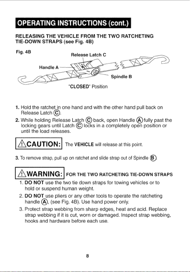
RELEASING THE VEHICLE FROM THE TWO RATCHETING
TiE-DOWN STRAPS (see Fig. 4B)
Fig 4B
Release Latch C
"CLOSED _ Position
1. Hoid the ratchet in one hand and with the other hand puli back on
Release Latch @o
until the toad re_eases.
[_CAUTION:j The VEHICLE witi reiease at this point.
& 'To remove strap pu_/up on _atchet and slide strap out of Spindle _.
1 DO NOT use the two tie down straps for towing vehicles or to
ho_d or suspend human weight.
2. DO NOT use pliers or any other tools to operate the ratchefing
handte _, (see Fig. 4B}. Use hand power only:
3 Protect strap webbing from sharp edges heat and acid. Replace
strap webbing if t is cut worn or damaged, hspect strap webbing
hooks and hardware before each use.
Page 9
(see Fig. 1, 2)
TO ADD HYDRAULIC JACK OIL
the oi_ fill plug DO NOT ALLOW dirt o_ debris to ente_ the system
TO REPLACE HYDRAULIC JACK OiL
° Open the release valve by pressing down on the re_ease peda_
Unscrew and remove oil fil_ plug.
- Turn entire jack over so that a_ d the old oi_ will drain out d the oi_ fiH hole.
NOTE: When draining oil use a proof container and ALWAYS fo_ow ALL
local and state waste disposa_ guidelines
* After a_! of the oid oil has drained out d the jack, turn the _ack back e/vet to a
DO NOT ALLOW dirt and debris to enter the system
-Repiace and tighten oil fili piug.
iMPORTANT: When adding or replacing oH, ALWAYS use a goed
grade d (SAE 5 W) hydraulic jack oi_ NEVER use brake fluid, alcehoi
glycerin, detergent motor oi$ or dirty oH d any kind Improper oit usage
will cause serious internal damage to jack.
LUBRICATION
, Use a good grade e_ lubricating ell on a_ moving parts when needed
STORING
, When iack is not in use or when storing the jack,
ALWAYS have the lift saddles in the lowest (downi_ position
RUST PREVENTION
Check power unit (hydrau}ic ram} see pa_s _ist Fig 2 _etter _) page 5
every two monfhs or sooner based on use for any rust or corrosion
Clean and wii_ down with oil cloth.
Page 10
Maximum load capacity: 1500 ibs (681kg,}
_cking Positions: 1t 3t4 in, t4 114 in and
16 1/2 in
Size: 35 1_ x17 x t4 inches
Weight without the two tie*down straps
and the two adapter plates (sold separately): _ 77 _bs_
PROBLEM
Jack will not
ftft to full
height
For purging air, see Purging Air Instructions on page 3,
CAUSE
1. Air in hydraulic
system
2, Release valve is
stuck
t Oil ieve/is tow
2. Air in hydrau%
system
1, Air in hydraulic
system
2, Dirty oit
I, Excessive weight
2 Oil level is bw
10
SOLUTION
system*
2 Trander weight Ioad and
clean valve
I. Ftl to recommended levei
2 Purge air from hydraulic
system. *
l Purge air from hyd_aulic
system"
2 Change oi_ Use SAE 5W
f, Decrease weight or change
to a higher capacity iacL
2. FH_ to recommended level
Page 11
NOTES
11
Page 12
NOTES
12
Page 13
Manual del usuario
iCH' MnWI
1 I
Modelo No.
875,50190
PRECAUC:I6N: Lea, comprenda y siga todas
tas normas de segur}dad y ias instruoeiones de
funcionamiento de es_e manual antes de ut#iza_
este producto
Scats, Roebuck and Co,, Hoffman Estates, IL 60179 U_S.A
Vtstte nuestto sttto web Ct_-tsman: www, sears,com/cra_eman
• _uridae
• Garantla
Caraotertst:tcas y
funcionamlento
" Mantenimiento
Page 14
GARANTIA COMPLETA DE UN A_/O DEL PRODUCTO CRA_SMAN
Seste pr_¢_o @dtsmaa _a_a debido a an de_ecte de mal_ma_ e de _abdeaci_'_
ESTADOS UNIDOS PARA OBTENER UN REEMP_O GFIATUITO,
Esta ga@ntia/e o_xga de_os bgales esp\ecff_sos Usled puede _÷ner eta'as
de,aches qua redan de un estado a etre_
Sears, R_>sbu_ a_wJ Co. Dept 817 WA h%fimaa , IL 60179
iGUARDE ESTAS INSTRUCCIONES!
LEA TODAS LAS INSTRUCC|ONES
[| ADVERTENClA: ]
• KI in€amp/miea_o de/as eti¢_e_as de adve_tsneia de/pred_ste
puede res@tar en s _rsona_ea o daao8 a _a p_opi_a_d,
• E_studie compmnda y siga todas iaS inst_uccio_'_e_ ar_tes de usa_ eeted sposRivo
,' Este gate tiers Una capac_dad maxima de 1.500 Ebras NO exae@a Ia capac_dad
nominal de/p_odu:c_o
. 8_LO use el gate sabre _na supedic e duma y r_ veiada que pueda sop,e_tar e] vehi¢@o.
. Levante s@lo e_ _as _r_as de_ vehic@e espec ficadas per el rabbi€sate dei vehtcat&
• SI_MPRE _s amarres pars asegu_a_ e/v:ehk:@o a gato_
NUNCA maeva e_ vehieu o cos eS gate si las crates no estar_ aseguradas o e_ su I_gar:
. SI_MPRE U_ la ba_a de btoqueo de a]tura cu_.s_do el vehicu_e e_@ e_evado papa
evi_ar qua se baie aecidenta#_}ente.
- SI_MPR_ bs4_ el vehic@o a h p_ici@} m&s baia posib_e ANTES de _ler_tar
t_aespodado e msve_o.
. NO a_tere de a_guna ma_era asks, pr(_uete.
• SI_MPR_ inapecc_or_e e/gate antes de cads use
. NO use e_ pro4acto si escapes de f/_ido y/o pieza/s re,as dob_adas,
agde_adas o da_adas
• _med_atamente despu@s de lev_tat @ vehica/o_ assg@ese de qua _a barfs
de bloquee de aitu@ est@ hada
,, SIEMPRE _se _enieS de seguddad suande use este prsducto_
d:e/gate pueda saerIe eeeima_ ya que pedda eaasa_
lesiones perssna_es graves.
14
Page 15
Du_ante el eerie y ent_e:#a_ e[ aire puede q_edar at_apado en e! dstema hi@Au_ico
Io que ir_terfiefe coa el rendimienlo de lew_ntamienio dei gate Sga estos pa_s
para _iLera[ el aire
, Abra la vaSvula @ liberaci6n p_es_onando e_ _dal @ ]iberaci6n_
(yea _as Rgs, 't y 2)
* ReJtire e/_a_sn de I_enado de aceite (,tea la Fig t)
, _m_e el _dal @ (yea ias Figs ! y 2) 6 a 8 veces para liberar cua/q[;ie_ cantidad
de aire presudzado que pt_da habe_ qu_ado atrapado en @ tanque de aceite
(sir_ema hidraulico).
* Asege_e_ de que el nive_ de aceite est¢ juste f_ debajo de/aguje_o de la ro_a dei
agujere para el _ap@n de/_enado de aceite. Si es necesario agregar aceite, siga Ias
• Vueiva a col_ar e/laCe de _lenado de a@ite y apri6teio,
Este gate (yea _as Figs 1, 1A t B y 2) tiene caractedsticas especiates inco@oradas
que to hacen ideal para realizar reparaciones menores_ cambios de aceite
limpiezas y m_s_ Entre estas se encuentran:
* Capacidad de carga de 1,500 I_ papa levantar la mayoria de/as rear.si!!eras y Y_.
Usa b<_mba hidr_uiica de accian r_pida con pedal _._ (yea [a Fig 2) pate faeilitar el
ieva[_tamiento de 5-1,8 ' a t7 _ _bre la pa_e delantera de ia base del gato_
Puede adquid_ dos piacas adaptadoras, veedidas par _parado (yea/a Fig. 1A)_
para pem_ifir e! levantamiento de/vehiculos hasl_a t 9 _' sabre la pade dela#tera
de _a ba_ del gate.
. Barra de bbqueo de aitura de 3 posiciones que ptoporciena bk×_ueo de ii
rapida a _res niveles: 11 3/4" 14 1/4" y 16 1/2" (yea h Fig. t).
IMPORTANTE: AI tevantar el vehicu_o, et gate debe set bbqueado
INMEDIATAMENTE en una de tas tres aituras de fevaetamiento
. Uberaei6n cont_olada per pedat de cont_ol a precisi6n para baiar el vehicu_o
. Puede set usade ®me carretitta para mover e_ veh_calo a u_a ubicaci6n
cenvenieste para reparado o a]macena_lo_
. Maniia ee T (Fig_ 1) para mayor coetro_ euando use e_ gate cz.)mo carre_i_la para
mover el vehicub a! _ugar de trabajo o a]ma.senamiento
. E_ gate tambien inc_uye dos amarres de trinquete de I de a_¢ho × 15 pies de
_argo (yea la Fig, 1B} para ayudar a asegurar el vehicu_o,
- E_ gate cuenta con tomi/los de bbqueo ajustables y ruedas cen bl_ueo gara
aumentar _a estabiiidad (yea la Fig. 1 )
15
Page 16
* Puede adquidr dos placas adaptadoras de 2 '_ (yea la Fig IA) pare a_adir 2" a la
altura maxima de leva_tamiento de 16 1/2 '_' de_ gato papa a _as mo_os
de motocross de chasis alto que requie_ar_ 18 t/2' de altura,
, _ncluye dos amarres de trinquete de 1 '_ de ancho x 15 pies de iargo (yea _a Fig. 1 B)
Ruedas de bl_ueo
Torailtos de bto_
Barra de b_oquee de a|tura
ueo
16
Page 17
M
E 3 2 I
(yea la Fig, 2)
!7
Page 18
e# ia bar_a de
tuercas MS (2}
4_ Instafe la maniia e_ T_en la vara de conexiSn (_ usar_do el pasador (3}
5_ A_sg_Jrese de que t_as las conexiones est@_ bies ap_etadas
PARA LEVANTAR EL VEHICULO
(yea las Figs, 2 y 3)
1, Cofoque e ga_o s_e una supe_cie
d_a y n;
2, Papa evilar que ei vehisJb durance
e/}e_antami_nto, SOLO use !os puntos de_
_®hicufo espe _ar e_ fa_icant÷ en
el rnarwal del usuane de/vehicu!o_
3. Colcque e_ 9_to debajo dei _h[¢ulo de
con e_ pi6 la !engSe_a marca_ como LOOK '_ ( ) SIEMPRE aseg@ese @ que
et asiento y @ vehi'cub est¢_ ¢ s co_e,otamente ANTES de e,,antar el gato.
5, Use et pedai para ete_ eI veh_cub. Bombee e_ _da_ basra que e_ e×l_emo de a
barra de bioqueo _e s_ura 5e mu÷_a mas aIla dei dense de b_oqueo de posision
E! ex_remo de _a ba_a de o de al_ura caeca e_"_ posic_o_ pgr detr_s de_ dienle
de . Pres_o_e rite e_ peda_ de _i n de m_era queet e×_temo de
la bar_a se des_ice basra queda_ bqen recostado sobre d dien_e.
6. Usa ios ama_res (yea/a de fijaci_s de_ vehicvb er_/a p_gina 7)papa as÷g_ar
ei vehiculo _na vez que baya s_oleva_'_fado a la a_e_a a Apdete bie_ bs amar_es
PARA BAJA_ EL VEHICULO - Fig. 2
1. E_ve _evemen_e e/gato y ti_e de/dispositivo de _ befaci6n de blo@Jeo de at_uta para
ibe_ar la basra de de a_tu_a
2, Fiie e! disposi_t}vo de _i_eraci6n de b_oques de attu_a @ a_ r (_ para baiar
comp/e_amente e_: vehicu_,
3, P_sone e_ peda_ de Iibe_ad@ _ cob mucha suav dad pa_a baia_ el asiento
_,C_ y el vehicuIo.
t8
Page 19
/A PRECAUCthN'! Los ama_r_s s÷ a_lois_ y ei veh c{;_o se I b÷_a_ a
|_ '_' *! medda que se a_astfe el _ehicule_
F|JACi_N DEL VEH{CULO con los amartes de trinquete de
1 _ x 15 pies (yea fas Figs, 4 y 4A)
Fig 4 Palanca de _tbetad6n C Eje B
Mantja A ....
Vista supedo_ e_ la pos ci6_ "ABIERTA"
3, Ap_iete et ama_e moviendo ta ma_i}a hacia ade_anle y hacia arras a modo de ld_quete
basra que et vehict_b este aseg_ad¢ Pa_ ma_tener el amarfe en posici6n mier_tras
b ap_Leta p_@ set rio so_, _er e_ a_T_srre resla_te a ma_ basra que e/
m, ism© e_e a_h_llado
4, Para bioquear ¢_ _r aque_e, col_u÷ h ma_iia de_ amarre _ e_ la _Yssic 6h cer_ada_
Papa w_.a_ da585 a_ vehic_._io NO a _iete demas_ad8 el a_:oa_e.
Fig. 4A
Moto de ¢_i"_s_s alt_ _ada
y bs dos ama_e_ @ _rinqsete_
19
Page 20
L_BERAC|_N DEL VEHICULO DE LOS DOS AMARRES
DE TR_NQUETE_ (yea |a Fig, 4B)
Fig, 48
Pa_n,ca de ll_raci6n C
Pos cl6f'_ CERRADA
mane y con la otra mane tire _a palanca
_ _.._,;.u.m..:_ _, vo.,,.o,o °°,,.%°,°°0 oo o.,o _omoo,o_
3, Papa retirar e_ amarte, tire det tdnquete hacia ardba y deslioe e_ amarre
basra saearlo del eje(_,
AMARRES DE TRINQUETE
I, NO use el amarre para _eme_ca_ veh{cu_es o para sos_ene_ o
soportar peso humano,
3, Proteja el tramado de_ amar_e de bordes afi_ados_ ca_o_ y _¢ido
Reemp/ace !a ehta del amar_'e si est_ co_tada _esgastada o daSada,
tnspeee one e_ t_amado de_ amarre, los ganchos y los aceesodos antes
de cada uso,
Page 21
(vea las Fig, 1 y 2)
PARA AI_iADIR EL ACEITE HIDRAULICO PARA GATOS
Con los as entos de levantam_ente compietamente bajos y e/gate a nivel
del piso, desenrosque y retire el tapSn de Henado de_ aceite Usando aceite
t_idreulico SAE 5W de alte grade pare gates !_ene e_ tanque de aceite haste
Ia pare inferior de _a rosca en el agujero de Henado de aceite Vue_va a eolocar
el tep6n de lenado de aceite y apt Ctelo, NO PERMITA que entre sueio o
desperdicios a_ sistema
PARA REEMPLAZAR EL ACE|TE HIORAULICO PARA C__TOS
• Abra la v&lw_ia de I beraci6e p_esionando e_ pedal de liberaci6n
Desenrosque y retire el tap6n de !lenado de aceite,
- V_)/tee e_ gate complete pare que todo el aceite viejo se drene a t_av6s
det aguieK) de/lenado deI aceite
NOTA: Cuando drene ace_e_ use un envase adecuado y SIEMPRE sign
TODAS Ins pautas locales y es_atales de e_iminac_6e de deeechos
• Despu6s de que e_ aceite vieio se haya drenado deI gate, vuelva a (_lecar
el gate en posiei6n rfive_ada pare Henar eI tanque con aceite nuevo_
• Bembee repidamente e_ pedai dei gate Q 6 a 8 veees papa liberar
euaiquier cantidad de aire presadzado.
- Usando acete h drAu_ico SAE 5W de aite grade pare 9atos_ _iene e_ tanque
de aceite has_a la parte nferior de la rosca en el aguiero de lienado de aeeite
NO PERMITA que ent_en sucio y desperdieios ai sistema
• Vue_va a eotocar el tapon de lIenado de aceite y aprietelo
IMPORTANTE: Cuando a_sada o reemptace e_ a/ceite SiEMPRE use un ace_te pare gat_es
hid_auiicos de grade alto ISAE 5W}_ NUNCA use _iga de frenos, a/ceho_ _/icedna, aceile
de motor detergente o aceite sucie de n ngGr_ tip_r_ Ei us{) de acete {nadecuado cssuear_
daises ietemes graves a_ ga_o
LUBRICACION
• Use aceite _ubdcante de alto g_ado en redan Ins piezas euando sea necesado
ALMACENAMIENTO
Cuande eI g_to no este en use eest@ a_mace_ado_ SIEMPRE baje coi"npietamen_e
et asiento
PR_V[NCt0N D_ 0XIDO
Verifiquega unJdad de energia (ariete hidr&ulico) (yea ia lista de piezas_
Fig, 2 ('J._) P&9. t7} cada dos meses (o antes depeediendo de! use} en busca
de se_a_es de 6×ido o eorrosien,, Limpie y pu_a con un patio de aeeite.
21
Page 22
Capac dad de earga maxima: 1.500 ibs (681 kg)
BIoqueo de posici6n: ........................................... II 3/4% t4 I/4'_ y 16 1/2 '_
TamaSo: 35 I/2 x 17 × 14 pt l,_das
Peso sin _os dos amarres y sin _as dos
p_acas adaptadoras (vendidas per sepamdo) ....... 77 _bs,
PROBLEMA
Et gate
no baja
completamente
E! gate
no levanta
hasta la altura
CAUSA
2 La valvula de
_iberavci6n es_
atascada
1 El nivei de aceite
esta bale
SOLUCION
2 Traasf era e_ peso y limpie
t. Ltene e_ dep6sito basra el
2 Purg_,_e e/aire de_ sistema
m_×tma
Le_antamlento
d_bi!
2. Aceite sucio
E! gate
no levanta
la carga
PaIsa purgar e_ aire yea _a seceion de instracciones
@ pt_ga det aire en Ia pagina 15,
I_ Peso excesivo
2_ Ei nive_ de aceite
esta bajo
22
la v_/vula
#ivel reeomendado
hidrau ice*
1. Purgue el aire dei sistema
hid_u_ico
2 Cambie e! aceite
Use acete SAE 5W
1 Reduzca et peso o ul_i_ ce ur_
gate de mayor capacidad
2 Liene ei dep<"_sita basra e
aivei recomendado
Page 23
NOTAS
23
Page 24
iiiiiiii¢
iiiiii"
iiiiii
iiiiii
iiiiii
iiiiii
iiiiii
iiiiii
iiiiii
iiiiii
iiiiii
iiiiii
iiiiii
iiiiii
For repair- in your home - of al| majar brand applial_s
iawn and garden equipment or heating and _ting systems_
no matter who made it, no matter who sold tt
For the replacement pa_s a_cessories and
owner's manuals that _u need to doAtoyourself,
For Sears professional insta/atien d home applances
aP_ item8 tke garage door openers arid water heaters_
1 _00_-MY'HOME ® _!,_s_3)
Ca/a_t_ime day or nigh_ (U,,S,,A a_d Canada}
iiiiii
iiiiiii .......................... iiiiii
i a _y_a_r_: I_.FOYER _ i
Your Home
_ Sea_S eem _a_
iiiiii 1_s R_ _ ...........


 Loading...