

Page 1
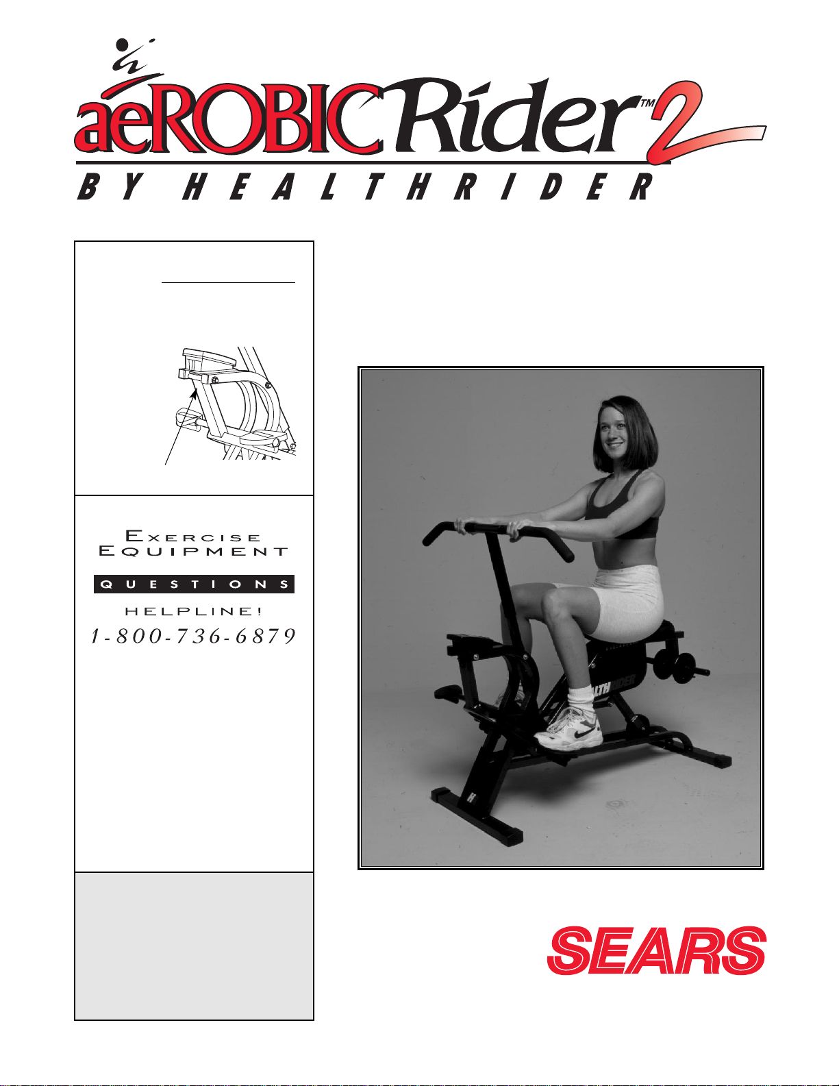
Model No. 831.287943
Serial No.
Patent Pending
The serial number can be found in
the location shown below. Write the
serial number in the space above.
CAUTION
Read all precautions and
instructions in this manual
before using this equipment.
Keep this manual for future
reference.
USER'S MANUAL
Serial Number Decal
SEARS, ROEBUCK AND CO., HOFFMAN ESTATES, IL 60179
Page 2

2
TABLE OF CONTENTS
IMPORTANT PRECAUTIONS . . . . . . . . . . . . . . . . . . . . . . . . . . . . . . . . . . . . . . . . . . . . . . . . . . . . . . . . . . . . .2
BEFORE YOU BEGIN . . . . . . . . . . . . . . . . . . . . . . . . . . . . . . . . . . . . . . . . . . . . . . . . . . . . . . . . . . . . . . . . . . .3
ASSEMBLY . . . . . . . . . . . . . . . . . . . . . . . . . . . . . . . . . . . . . . . . . . . . . . . . . . . . . . . . . . . . . . . . . . . . . . . . . . .4
ADJUSTMENT AND OPERATION . . . . . . . . . . . . . . . . . . . . . . . . . . . . . . . . . . . . . . . . . . . . . . . . . . . . . . . . . .8
MAINTENANCE AND TROUBLE-SHOOTING . . . . . . . . . . . . . . . . . . . . . . . . . . . . . . . . . . . . . . . . . . . . . . . . .11
CONDITIONING GUIDELINES . . . . . . . . . . . . . . . . . . . . . . . . . . . . . . . . . . . . . . . . . . . . . . . . . . . . . . . . . . . .12
PART LIST . . . . . . . . . . . . . . . . . . . . . . . . . . . . . . . . . . . . . . . . . . . . . . . . . . . . . . . . . . . . . . . . . . . . . . . . . . .14
EXPLODED DRAWING . . . . . . . . . . . . . . . . . . . . . . . . . . . . . . . . . . . . . . . . . . . . . . . . . . . . . . . . . . . . . . . . .15
ORDERING REPLACEMENT PARTS . . . . . . . . . . . . . . . . . . . . . . . . . . . . . . . . . . . . . . . . . . . . . . . .Back Cover
FULL 90 DAY WARRANTY . . . . . . . . . . . . . . . . . . . . . . . . . . . . . . . . . . . . . . . . . . . . . . . . . . . . . . .Back Cover
IMPORTANT PRECAUTIONS
WARNING: To reduce the risk of serious injury, read the following important precautions before
using the HEALTHRIDER®AEROBIC RIDER 2.
1. Read all instructions in this manual before
using the AEROBIC RIDER 2.
2. It is the responsibility of the owner to ensure
that all users of the AEROBIC RIDER 2 are
adequately informed of all precautions.
3. The AEROBIC RIDER 2 should not be used
by persons weighing more than 250 pounds.
4. Keep children under the age of 12 and pets
away from the AEROBIC RIDER 2 at all
times.
5. Place the AEROBIC RIDER 2 on a level surface during use. Cover the floor beneath the
AEROBIC RIDER 2 to protect it.
6. Regularly inspect and tighten all parts of the
AEROBIC RIDER 2.
7. When exercising, do not wear loose clothing
that could become caught on the AEROBIC
RIDER 2. Always wear athletic shoes.
8. The total weight of the user and the added
weights should not exceed 300 pounds.
9. Use the AEROBIC RIDER 2 only as described
in this manual.
10. The AEROBIC RIDER 2 is intended for home
use only. Do not use the AEROBIC RIDER 2
in any commercial, rental, or institutional
setting.
WARNING: Before beginning this or any exercise program, consult your physician. This is especially important for persons over the age of 35 or persons with pre-existing health problems. Read all
instructions before using. SEARS assumes no responsibility for personal injury or property damage
sustained by or through the use of this product.
Page 3
3
BEFORE YOU BEGIN
Thank you for selecting the new HEALTHRIDER
®
AEROBIC RIDER 2. The AEROBIC RIDER 2 offers a
unique form of low-impact exercise that uses both the
upper body and the lower body for greater cardiovascular benefits and increased toning.
For your benefit, please read this manual carefully
before using the AEROBIC RIDER 2. If you have
additional questions, please call our toll-free
HELPLINE at 1-800-736-6879, Monday through
Saturday, 7 a.m. until 7 p.m. Central Time (excluding
holidays). To help us assist you, please note the product model number and serial number before calling.
The model number is 831.287943. The serial number
can be found on a decal attached to the AEROBIC
RIDER 2 (see the front cover of this manual).
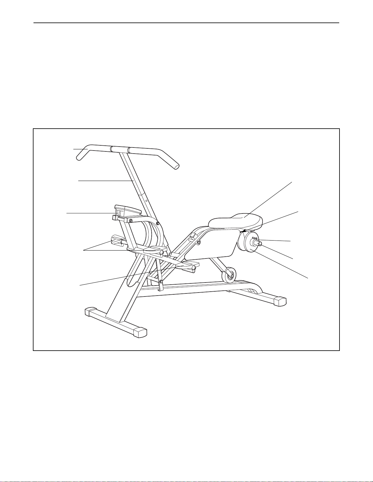
Before reading further, please review the drawing
below and familiarize yourself with the parts that are
labeled.
Handlebar
Padded Seat
Upper Pedals
Seat Knob
(Behind
Sideshield)
Lower Pedal
Monitor
Weight Tube
Weight Collar
Weight
Center Post
Page 4
4
ASSEMBLY
Before beginning assembly, carefully read the
following information and instructions:
• Assembly requires two persons.
• Place all parts in a cleared area and remove the
packing materials; do not dispose of the packing
materials until assembly is completed.
• Read each assembly step before you begin.
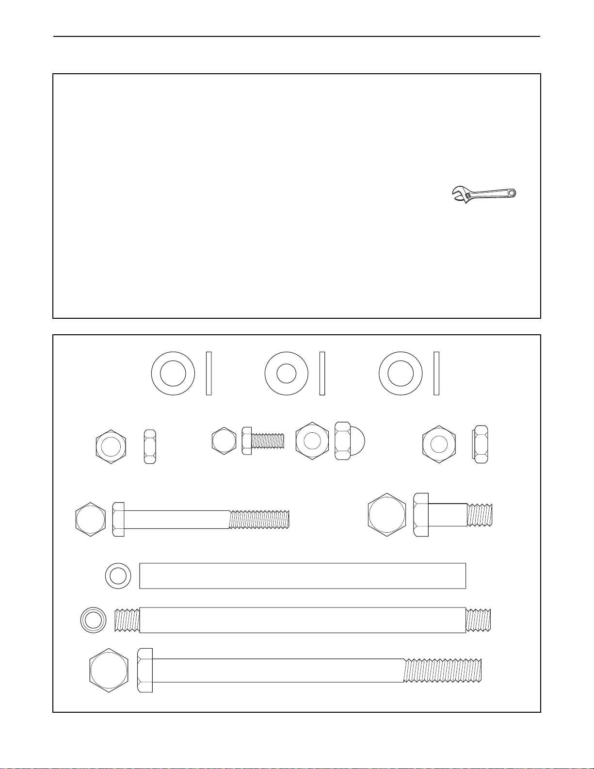
• To identify the small parts used in assembly, use
the part identification chart below. The number in parenthesis below each part refers to the
key number of the part. The second number
refers to the quantity needed for assembly. Note:
Some parts may have been pre-attached for
shipping purposes. If a part is not in the parts
bag, check to see if it has been pre-attached.
• Tighten all parts as you assemble them, unless
instructed to do otherwise.
• During assembly, make sure that all parts are oriented as shown in the drawings.
THE FOLLOWING TOOLS (NOT INCLUDED)
ARE REQUIRED FOR ASSEMBLY:
• Two (2) adjustable wrenches
• Lubricant, such as petroleum jelly or grease,
will also be required.
Assembly will be more convenient if you have the
following tools: Asocket set, a set of open-end or
closed-end wrenches, and a rubber mallet.
Plastic Washer (49)–2
M6 Hex Nut (54)–4
M6 Flat Washer (55)–4
Axle Fastener (56)–4
(either Bolts or Acorn Nuts)
Frame Axle (13)–2 (Internal Thread)
OR
Frame Axle (13)–2 (External Thread)
M8 x 120mm Bolt (57)–1
Rubber Washer (51)–4
M8 Nylon Jam Nut (7)–2
M8 x 1.375” Bolt (17)–1M6 x 60mm Bolt (53)–4
Page 5
5
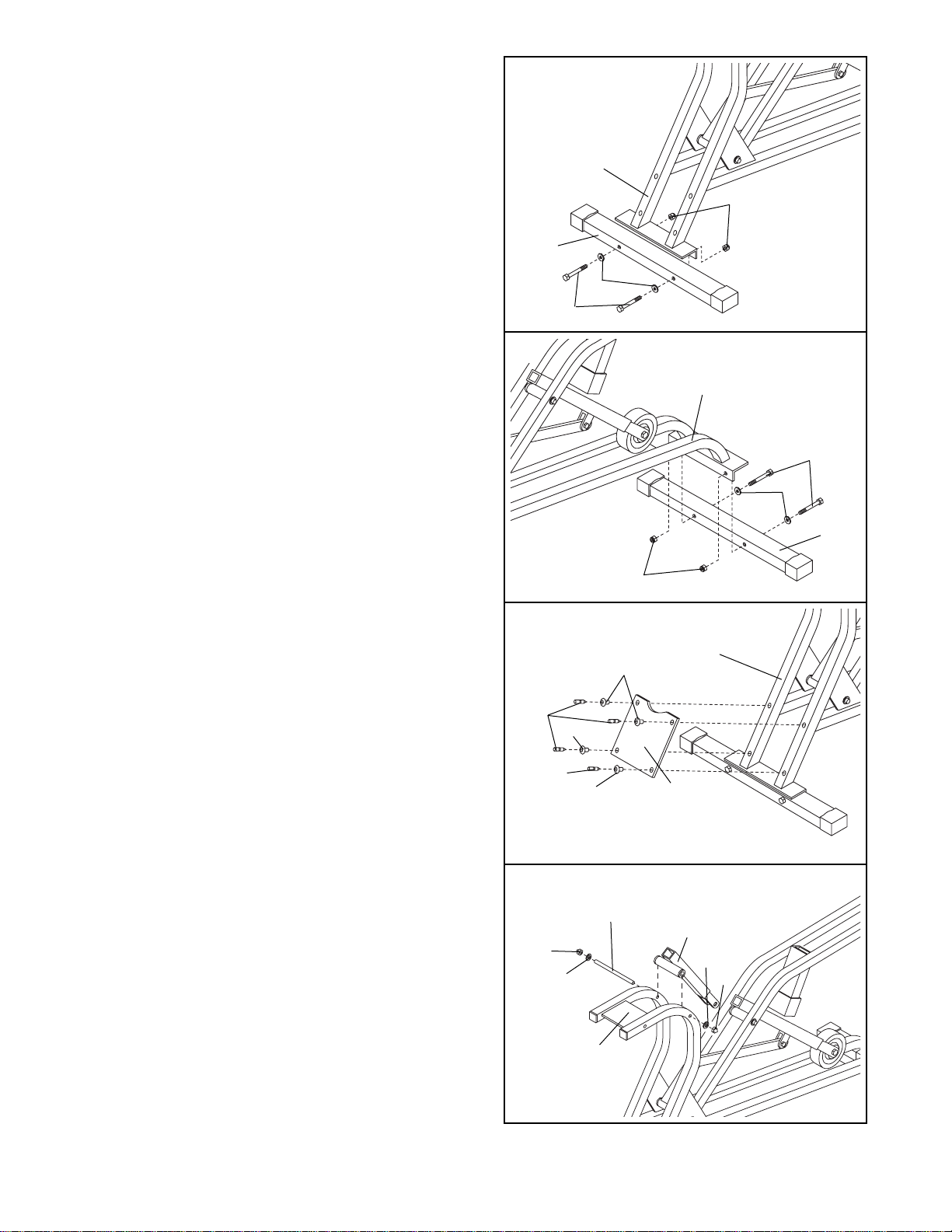
1. Before beginning assembly, make sure that you
have read and understand the information on
page 4.
Attach one of the Stabilizers (31) to the Main Frame
(1) with two M6 x 60mm Bolts (53), two M6 Flat
Washers (55), and two M6 Hex Nuts (54).
1
31
54
55
53
1
1
45
58
58
45
45
34
54
55
1
31
53
2. Attach the other Stabilizer (31) to the Main Frame
(1) with two M6 x 60mm Bolts (53), two M6 Flat
Washers (55), and two M6 Hex Nuts (54).
3. Attach the Front Cover Panel (34) to the Main
Frame (1) using four Fastener Bases (45) and four
Fastener Pins (58). First, insert the Fastener Bases
through the Cover Panel and into the Main Frame.
Next, push a Fastener Pin (58) into the hole in each
Fastener Base until it is flush with the Base.
4. Lubricate an Frame Axle (13). Attach the Handlebar
Swing Arm (5) to the Main Frame (1) with the
Frame Axle, two Rubber Washers (51), and two
Axle Fasteners (56).
Note: If the ends of the Frame Axles (13) are
internally threaded, the Axle Fasteners (56) will
be bolts; if the ends are externally threaded, the
Axle Fasteners will be acorn nuts (see the PART
IDENTIFICATION CHART on page 4).
4
3
1
51
56
51
56
5
Lubricate—13
2
Page 6

6
7
45
45
58
58
2
21
49
10
7
11
17
5
5
6
51
56
36
Hole
1
4
51
5. Push the Magnet Bracket (36) into the hole in the
Pedal Frame (4).
Lubricate an Frame Axle (13). Attach the Pedal
Frame (4) to the Main Frame (1) with the Frame
Axle (13), two Rubber Washers (51), and two Axle
Fasteners (56).
6. Attach the Left Side Shield (21) to the Seat Frame
(2) using three Fastener Bases (45) and three
Fastener Pins (58). First, insert the Fastener Bases
through the Side Shield and into the Seat Frame.
Next, push the Fastener Pin (58) into the hole in
each Fastener Base until it is flush with the Base.
Attach the Right Side Shield (22, not shown) in the
same way.
7. While another person holds the Long Link Arm (10)
and the Short Link Arm (11) in place, put two Plastic
Washers (49) between them. Then, connect the
Seat Swing Arm (5), the Long Link Arm (10), and
the Short Link Arm (11) using an M8 x 1.375” Bolt
(17) and an M8 Nylon Jam Nut (7).
8. Place the Seat (20) on the Frame (2). Slide the
Seat Washer (38) onto the Seat Knob Bolt (43) and
then tighten the Seat Knob (37) onto it.
Slide the Weight Bracket (8) onto the Seat Frame
(2) so that it slants away from the AEROBIC RIDER
2. Align the holes in the Weight Bracket with the
ones in the end of the Frame. Insert the M8 x
120mm Bolt through the Weight Bracket and the
Frame and secure it with an M8 Nylon Jam Nut (7).
8
2
20
43
38
57
7
37
8
Lubricate—13
56
Page 7

7
9. Depress the two buttons on the sides of the
Handlebar Assembly (6) with your thumb and forefinger. Insert the Handlebar Assembly (6) into the
Handlebar Swing Arm (5). Make sure that the buttons protrude through one of the two sets of holes
in the Handlebar Swing Arm. The upper holes offer
lower workout resistance; the lower holes offer
higher resistance.
Holes
6
Buttons
5
9
10
11
35
1
35
(–)
(+)
Battery
Cover
AA
Batteries
(–)
(+)
A
B
11. Remove the battery cover from the Monitor (35).
Insert two new AAbatteries into the Monitor. Identify
the negative (–) and positive (+) ends of the batteries. The springs in the battery compartment should
touch the negative ends of the batteries.
10. Slide the Monitor (35) fully onto the Main Frame (1)
as shown in inset drawing A. Press down on the
Monitor as shown in inset drawing B until it snaps
into place.
35
1
35
1
12. Make sure that all parts are properly tightened. To protect the floor or carpet from damage, place a mat
under the AEROBIC RIDER 2.
Page 8

ADJUSTMENT AND OPERA TION
DESCRIPTION OF THE MONITOR
The monitor offers five modes to provide you with
instant exercise feedback:
• Time—Displays
the elapsed time.
Note: If you stop
exercising, the
time mode will
pause after ten
seconds.
• Reps/Min—
Displays your
repetitions per
minute.
• Reps—Displays the total number of repetitions you
have completed, up to 3999. The display will then
reset to zero and continue counting.
• Calories—Displays the approximate number of
Calories you have burned.
• Scan—Displays all of the above modes, for approxi-
mately 5 seconds each, in a repeating cycle.
HOW TO OPERATE THE MONITOR
1. To turn on the power, press the select button or
simply begin exercising. When the power is
turned on, the time mode will automatically be
selected.
2. Select the desired mode:
Time, reps/min, reps, or calories mode—To select
one of these modes, repeatedly press the select
button. The mode indicators will show which mode
is selected. Make sure that the scan indicator
does not appear.
Scan mode—When the scan mode is selected,
the scan indicator will appear and a mode indicator will show which mode is currently displayed.
To select the scan mode, repeatedly press the
select button.
3. The monitor has an “auto-off” feature. If the
pedals are not moved and the select button is not
pressed for four minutes, the power will turn off
automatically in order to conserve the batteries.
ADJUSTING THE SEAT
To adjust the position of the seat,
loosen the knob
under the seat,
move the seat to
the desired position, and then
retighten the knob.
To determine if the
seat is properly
adjusted, sit on the seat and pull the handlebar as
close as possible to your stomach. Your legs should
be almost straight, with your knees bent slightly.
ADDING AND REMOVING WEIGHT
The AEROBIC
RIDER 2 features a
weight bar that lets
you increase the
intensity of your
exercise by adding
weights. To add
weights, first
remove the weight
collars from the
weight bar. Slide
the desired amount of weight onto the weight bar and
reattach the weight collars. Note: Place equal
amounts of weight on both sides of the weight
bar. The combined weight of the user and added
weights should not exceed 300 pounds.
CHANGING THE POSITION OF THE HANDLEBAR
To exercise the
muscles of the
lower body, the
position of the handlebar can be
changed. Remove
the Swing Arm Cap
(28) from the
Wheel Swing Arm
(3). Next, press the
Snap Buttons (46)
and slide the Handlebar Assembly (6) out of the
Handlebar Swing Arm (5). Press the Snap Buttons
again and insert the Handlebar Assembly into the
Wheel Swing Arm (3). Make sure that the Snap
Buttons snap into the holes in the Wheel Swing
Arm. Press the Swing Arm Cap (28) onto the
Handlebar Swing Arm (5).
a
a
a
a
a
a
a
aa
a
aa
aaa
8
Seat
Knob
Weight
Collar
Weight
28
46
5
3
6
Page 9

9
We strongly recommend that you begin every exercise session in this position. As a warm-up, it provides a balanced workout, distributing the emphasis between upper and lower body. Vary emphasis by pulling more with the
arms or pushing more with the legs. Keep your back vertical and upright at
all times. You should also vary your hand grip to target certain muscle
groups. For example, a wide overhand grip will target your shoulders; a
close overhand grip (shown) will target your triceps; and a close underhand
grip will target your biceps.
Muscles affected: All Major Muscle Groups
STANDARD WORKOUT POSITION
3
2
1
As your strength increases, you’ll want to challenge yourself by toning your
forearms even more. Use the wrist roll with either the close or wide overhand grip. As you pull the handlebar toward your stomach, roll your knuckles forward in a smooth motion.
Muscles affected: Forearm Flexors
WRIST ROLL
Grip the center post high with one hand above the other. Perform ten repetitions. Change your hand positions and perform the same number of repetitions. For greater emphasis try one hand at a time.
Muscles affected: Biceps and Chest
CENTER POST GRIP
PROPER EXERCISE FORM
The following tips are provided to help you get the
most from your exercise routine:
• Always start each exercise session in the
standard workout position to warm up.
• You should be able to feel yourself pivot or bend
from the hip, not from the back. Don’t round your
back as the bar moves forward.
• Always bring the handlebar as close to your stom-
ach or rib cage as possible. If you are new to
exercise, don’t extend the bar too far forward for
the first few weeks of your exercise program. As
your back becomes stronger and more flexible,
allow the handlebar to travel farther forward for
increased range-of-motion.
• Change grip positions, thumb positions, and toe
positions often to add variety, endurance, and balance to each workout.
• Always place the balls of your feet in the centers
of the pedals.
Page 10

10
Place the ball of each foot in the middle of each pedal. Push with your toes
pointed forward, then pull your feet back with toes up and heels down. This
tones the lower legs. Start with just a few minutes per session and gradually increase with each workout.
Muscles affected: Shins and Calves
TOES STRAIGHT
7
6
5
4
The direction which your toes are turned will vary the effect of your workout. If your toes are turned slightly in while pointing and flexing, this
emphasizes the outer calves. If your toes are turned slightly out while
pointing and flexing, this emphasizes the inner calves. You can also turn
you toes out and open your knees to tone your inner thighs. Regardless of
which toe position you choose, always keep your kneecap in line with your
toes.
Muscles affected: Calves and Thighs
TOES TURNED
Place your feet on the upper pedals and choose any grip.
Muscles affected: Arms, Upper Back, and Chest
UPPER BODY EMPHASIS
Grip the center post low and place your feet on the lower pedals. For more
emphasis on the stomach, tighten your abs and pull them in.
Muscles affected: Abdomen, Legs, and Lower Back
LOWER BODY EMPHASIS
Page 11

MAINTENANCE AND TROUBLE-SHOOTING
Inspect and tighten all parts of the AEROBIC RIDER 2 regularly. The AEROBIC RIDER 2 can be cleaned with a
soft, damp cloth; do not use solvents. To prevent damage to the monitor, keep liquid away from the monitor and
keep the monitor out of direct sunlight. When storing the AEROBIC RIDER 2, remove the batteries from the monitor.
HOW TO REPLACE THE BATTERIES
If the display of the monitor becomes dim, the AAbatteries should
be replaced. Remove the battery cover from the monitor. Remove
the old batteries. Insert two new batteries into the monitor. Identify
the negative (–) and positive (+) ends of the batteries. The springs
in the battery compartment should touch the negative ends of the
batteries.
Re-attach the battery cover to the monitor.
HOW TO LUBRICATE THE AEROBIC RIDER 2
Every three months, a small amount of light multi-purpose oil
should be applied to the AEROBIC RIDER 2. Apply a few drops of
oil between the axle caps or Axle Fasteners and the frame in the
locations shown at the right. Make sure to apply oil to both sides of
the AEROBIC RIDER 2.
11
Monitor
(–)
(+)
Battery
Cover
AA
Batteries
Apply Oil
Page 12

12
CONDITIONING GUIDELINES
The following general guidelines will help you to plan
your exercise program. Remember that proper nutrition and adequate rest are essential for successful
results.
EXERCISE INTENSITY
Whether your goal is to burn fat or to strengthen your
cardiovascular system, the key to achieving the
desired results is to exercise with the proper intensity.
The proper intensity level can be found by using your
heart rate as a guide.
The chart below shows recommended heart rates for
fat burning, maximum fat burning, and cardiovascular
(aerobic) exercise.
To find the proper heart rate for you, first find your age
near the bottom of the chart (ages are rounded off to
the nearest ten years). Next, look above your age and
find the three numbers in light grey boxes. The three
numbers are your “training zone.” The lowest number
is the recommended heart rate for fat burning; the
middle number is the recommended heart rate for
maximum fat burning; the highest number is the recommended heart rate for aerobic exercise.
Fat Burning
To burn fat effectively, you must exercise at a relatively low intensity level for a sustained period of time.
During the first few minutes of exercise, your body
uses easily accessible
carbohydrate calories
for energy. Only after the first few minutes of exercise does
your body begin to use stored
fat calories
for energy. If
your goal is to burn fat, adjust your pace until your
heart rate is near the lowest number in your training
zone as you exercise.
Maximum Fat Burning
For increased fat burning, adjust your pace until your
heart rate is near the middle number in your training
zone as you exercise.
Aerobic Exercise
If your goal is to strengthen your cardiovascular system, your exercise must be “aerobic.” Aerobic exercise
is activity that requires large amounts of oxygen for
prolonged periods of time. This increases the demand
on the heart to pump blood to the muscles, and on the
lungs to oxygenate the blood. For aerobic exercise,
adjust your pace until your heart rate is near the highest number in your training zone.
HOW TO MEASURE YOUR HEART RATE
To measure
your heart rate,
first exercise
for at least four
minutes. Then,
stop exercising
and place two
fingers on your
wrist as
shown. Take a
six-second
heartbeat count, and multiply the result by 10 to find
your heart rate. For example, if your six-second heartbeat count is 14, your heart rate is 140 beats per
minute. (A six-second count is used because your
heart rate will drop rapidly when you stop exercising.)
Adjust your pace until your heart rate is at the desired
level.
WORKOUT GUIDELINES
Each workout should include the following three parts:
A warm-up, lasting 5 to 10 minutes. Begin with slow,
controlled stretches, and progress to more rhythmic
stretches to increase the body temperature, heart rate,
and circulation in preparation for strenuous exercise.
(Refer to SUGGESTED STRETCHES on page 13.)
WARNING: Before beginning this or any exercise program, consult your physician. This is
especially important for persons over the age
of 35 or persons with pre-existing health
problems.
Page 13

13
Training zone exercise, consisting of 20 to 30 min-
utes of exercising with your heart rate in your training
zone. (See the chart on page 12 to find your training
zone.)
A cool-down, with 5 to 10 minutes of stretching.
Thorough stretching offsets muscle contractions and
other problems caused when you stop exercising suddenly. Stretching for increased flexibility is also most
effective after exercising. A proper cool-down should
leave you relaxed and comfortably tired.
EXERCISE FREQUENCY
To maintain or improve your condition, plan three
workouts each week, with at least one day of rest
between workouts. After a few months of regular exercise, you may complete up to five workouts each
week, if desired. The key to success is make exercise
a regular and enjoyable part of your everyday life.
SUGGESTED STRETCHES
The correct form for several basic stretches is shown at the
right. Move slowly as you stretch—never bounce.
1. Toe Touch Stretch
Stand with your knees bent slightly and slowly bend forward
from your hips. Allow your back and shoulders to relax as you
reach down toward your toes as far as possible. Hold for 15
counts, then relax. Repeat 3 times. Stretches: Hamstrings,
back of knees and back.
2. Hamstring Stretch
Sit with one leg extended. Bring the sole of the opposite foot
toward you and rest it against the inner thigh of your extended
leg. Reach toward your toes as far as possible. Hold for 15
counts, then relax. Repeat 3 times for both legs. Stretches:
Hamstrings, lower back and groin.
3. Calf/Achilles Stretch
With one leg in front of the other, reach forward and place
your hands against a wall. Keep your back leg straight and
your back foot flat on the floor. Bend your front leg, lean forward and move your hips toward the wall. Hold for 15 counts,
then relax. Repeat 3 times for both legs. To cause further
stretching of the achilles tendons, bend your back leg as well.
Stretches: Calves, achilles tendons and ankles.
4. Quadriceps Stretch
With one hand against a wall for balance, reach back and
grasp one foot with your other hand. Bring your heel as close
to your buttocks as possible. Hold for 15 counts, then relax.
Repeat 3 times for both legs. Stretches: Quadriceps and hip
muscles.
5. Inner Thigh Stretch
Sit with the soles of your feet together and your knees outward. Pull your feet toward your groin area as far as possible.
Hold for 15 counts, then relax. Repeat 3 times. Stretches:
Quadriceps and hip muscles.
1
2
3
4
5
Page 14

PART LIST—Model No. 831.287943 R1100A
14
1 1 Main Frame
2 1 Seat Frame
3 1 Wheel Swing Arm
4 1 Pedal Frame
5 1 Handlebar Swing Arm
6 1 Handlebar Assembly w/Foam Grip
7 5 M8 Nylon Jam Nut
8 1 Weight Bracket
9 2 Weight Collar
10 1 Long Link Arm
11 1 Short Link Arm
12 1 Seat Bracket
13 2 Frame Axle
14 1 Seat Axle
15 1 Wheel Mount Axle Assembly
16 1 M8 x 1.25” Wheel Bolt
17 1 M8 x 1.375” Bolt
18 2 M8 x 1.25” Bolt
19 1 Bumper Plate
20 1 Seat
21 1 Left Side Shield
22 1 Right Side Shield
23 2 Left Pedal
24 2 Right Pedal
25 5 Stabilizer Endcap
26 1 Bumper Spacer
27 1 Rubber Wheel
28 1 Swing Arm Cap
29 8 Medium Bushing
30 4 Short Bushing
31 2 Stabilizer
32 1 Middle Foam Grip
33 2 Foam Grip
34 1 Front Cover Panel
35 1 Monitor
36 1 Magnet w/Bracket
37 1 Seat Knob
38 1 Seat Washer
39 2 1.25” Square Endcap
40 4 1” Square Endcap
41 4 Pedal Cap
42 4 M12 x 1.25” Bolt
43 1 Seat Knob Bolt
44 2 M8 x 1.25” Seat Bolt
45 10 Fastener Base
46 1 Dual-end Snap Button
47 4 3/8” Hat Cap
48 2 1” Round Endcap
49 6 Plastic Washer
50 1 1” x 2” Endcap
51 8 Rubber Washer
52 2 5 lb. Weight
53 4 M6 x 60mm Bolt
54 4 M6 Hex Nut
55 4 M6 Flat Washer
56 4 Axle Fastener
57 1 M8 x 120mm Bolt
58 10 Fastener Pin
# 1 User’s Manual
Note: “#” indicates a non-illustrated
part. Specifications are subject to
change without notice. For information
about ordering replacement parts,
refer to the back cover of this manual.
Key
No. Qty. Description
Key
No. Qty. Description
Key
No. Qty. Description
Page 15

43
EXPLODED DRAWING—Model No. 831.287943 R1100A
15
12
44
57
48
52
40
7
45
50
20
22
45
38
19
47
37
51
26
45
21
25
15
58
2
51
48
47
8
28
45
5
49
9
56
53
55
25
25
31
54
47
51
1
14
25
31
54
27
16
49
18
30
10
49
30
56
51
7
3
7
29
17
29
7
58
6
33
33
46
35
32
41
29
56
51
42
13
41
42
29
56
24
51
13
40
39
24
40
36
39
29
23
23
51
41
47
42
25
45
34
58
30
4
11
7
30
49
18
45
58
55
53
Page 16

Part No. 159053 R1100A Printed in China © 2000 Sears, Roebuck and Co.
QUESTIONS?
If you find that:
• you need help assembling or
operating the AEROBIC RIDER 2
• a part is missing
• or you need to schedule repair
service
call our toll-free HELPLINE
1-800-736-6879
Monday–Saturday, 7 am–7 pm
Central Time (excluding holidays)
REPLACEMENT
PARTS
If parts become worn and need to
be replaced, call the following tollfree number
1-800-FON-PART (366-7278)
The model number and serial number of your HEALTHRIDER
®
AEROBIC RIDER 2are listed on a decal attached to the frame.
See the front cover of this manual to find the location of the decal.
All replacement parts are available for immediate purchase or
special order when you visit your nearest SEARS Service Center.
To request service or to order parts by telephone, call the toll-free
numbers listed at the left.
When requesting help or service, or ordering parts, please be
prepared to provide the following information:
• The MODEL NUMBER of the product (831.287943)
• The NAME of the product (HEALTHRIDER®AEROBIC RIDER 2)
• The PART NUMBER of the PART (see pages 14 and 15 of this
manual)
• The DESCRIPTION of the PART (see pages 14 and 15 of this
manual).
HealthRider is a registered trademark of ICON Health & Fitness, Inc.
ORDERING REPLACEMENT PARTS
FULL 90 DAY WARRANTY
For 90 days from the date of purchase, if failure occurs due to defect in material or workmanship in this
SEARS EXERCISER, contact the nearest SEARS Service Center throughout the United States and
SEARS will repair or replace the EXERCISER, free of charge.
This warranty does not apply when the EXERCISER is used commercially or for rental purposes.
This warranty gives you specific legal rights, and you may also have other rights which vary from state
to state.
SEARS, ROEBUCK AND CO., DEPT. 817WA, HOFFMAN ESTATES, IL 60179
 Loading...