

Sears 831.287602,Lifestyler C760 Owner's Manual

Model No, 831.287602
Serial No.
The se,_alnumber can be found in the
locationshown below. Write the serial
number inthe space above.
Serial Numbec"Decal
E_X E_ R C I S I___
E:Q U I P M E_ N'[-
H EhPLI N E.!
l - 800- 7;36- 5879
CAUTION!
Read all safety precautions and
instructions in this manual before
using this equipment. Keep this
manual in a safe place for future
reference.
PATENT PENDING
TRIPLEACTION. ELECTROMAGNETICSILENTDRIVE
OWNER'S MANUAl
SEARS, ROEBUCK h,ND CO., HOFFM/AN ESTATES, IL 60179
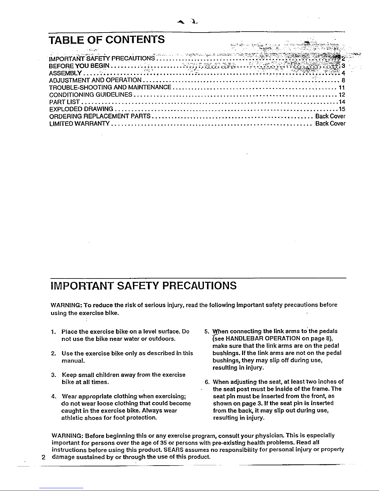
TABLE OF CONTENTS ° :
IMPORTANT SAFETY PRECAUTIONS .............................. _.-, ,-:_ o.;:- .__o___ ,-_'-"._ -. __: !_2
ASSEMBLY ...................... _............................................... .......... ,. 4
ADJUSTMENT AND OPERATION ..................................................... : ....... 8
TROUBLE-SHOOTING AND MAINTENANCE ................................................... 11
CONDITIONING GUIDELINES ............................................................... 12
PART LIST ............................................................................... 14
EXPLODED DRAWING ..................................................................... 15
ORDERING REPLACEMENT PARTS ................................................... Back Cover
LIMITED WARRANTY .............................................................. Back Cover
IMPORTANT SAFETY PRECAUTIONS
WARNING: To reduce the risk of serious injury, read the following important safety precautions before
using the exercise bike.
1. Place the exercise bike on a level surface. Do
not use the bike near water or outdoors.
2. Use the exercise bike only as described in this
manual.
3. Keep small children away from the exercise
bike at all times.
4. Wear appropriate clothing when exercising;
do not wear loose clothing that could become
caught in the exercise bike. Always wear
athletic shoes for foot protection.
5o
When connecting the link arms to'the pedals
(see HANDLEBAR OPERATION on page 8),
make sure that the link arms are on the pedal
bushings. If the link arms are not on the pedal
bushings, they may slip off during use,
resulting in injury.
6.
When adjusting the seat, at least two inches of
the seat post must be inside of the frame. The
seat pin must be inserted from the front, as
shown on page 3. If the seat pin is inserted
from the back, it may slip out during use,
resutting in injury.
2
WARNING: Before beginning this or any exercise program, consult your physician. This is especially
important for persons over the age of 35 or persons with pre-existing health problems. Read all
instructions before using this product. SEARS assumes no responsibility for personal injury or property
damage sustained by or through the use of this product.
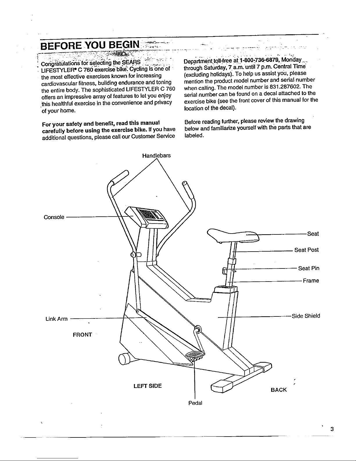
BEFORE YOU ....
' Congratulations for se!ecting the .SEARS. _'_,,_-:__: Departmenttqll-fme at.1-800:736-6879, Monday ....
LIFESTYLEF_ C 760 exemisebil<e_ c_yding-isbneoi through Saturdayl 7 a-m.until 7 p.m. Central Time
the most effective exercises known for increasing
cardiovascular fitness, building endurance and toning
the entire body. The sophisticated LIFESTYLER C 760
offers an impressive array of features to let you enjoy
this healthful exercise in the convenience and privacy
of your home.
(excluding holidays). To help us assist you, please
mention the product model number and sedal number
when calling. The model number is 831.287602. The
sedal number can be found on a decal attached to the
exercise bike (see the front cover of this manual for the
locationot the decal).
For your safety and benefit, read this manual Before reading further, please review the drawing
carefully before using the exercise bike. If you have below and familiarize yourselfwith the parts that are
additional questions, please call our Customer Service labeled.
Handlebars
Console
Seat
Seat Post
Seat Pin
Frame
LinkArm
Side Shield
FRONT
LEFT SIDE
Pedal
BACK
3
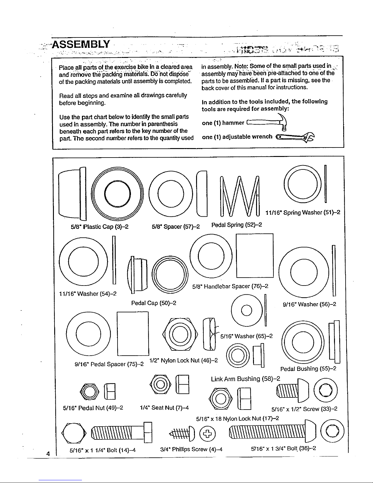
: :-ASSEMBLY .....
Place all pa_rtsof the exemise bike in a cleared area
and remove th'_'l_.cking m_t_ials: DSh0t clisp6se_'
of the packing materials until assembly is completed.
Read all steps and examine all drawings carefully
before beginning.
Use the part chart below to identify the small parts
used in assembly. The number in parenthesis
beneath each part refers to the key number of the
part. The second number refers to the quantity used
in assembly. Note: Some of the small parts used in _.-
assembly may_ha(ielbeeh p_'e-attached to one Ofthe
parts to be assembled. If a part is missing, see the.
back cover of this manual for instructions.
In addition to the tools included, the following
tools are required for assembly:
one (1) hammer £-------_
one (1) adjustable wrench
f
5/8"
=lastic Cap (3)-2 5/8" Spacer (57)-2
Pedal Spring (52)-2
11/16" Spring Washer (51)-2
5/8" Handlebar Spacer (76)-2
11/16" Washer (54)-2
5/ )-2
9/16" Pedal Spacer (75)-2 1/2" Nylon Lock Nut (
5/16" Pedal Nut (49)-2 1/4" Seat Nut (7)-4
9/16" Washer (56)-2
Pedal Bushing (55)-2
Link Arm Bushing (58)-_
G _ 5/16" x 1/2" Screw (33)-2
5/16" x 1 1/4" Bolt (14)-4
3/4" Phillips Screw (4)-4
5716" x 1 3/4" Bolt (36)-2
4
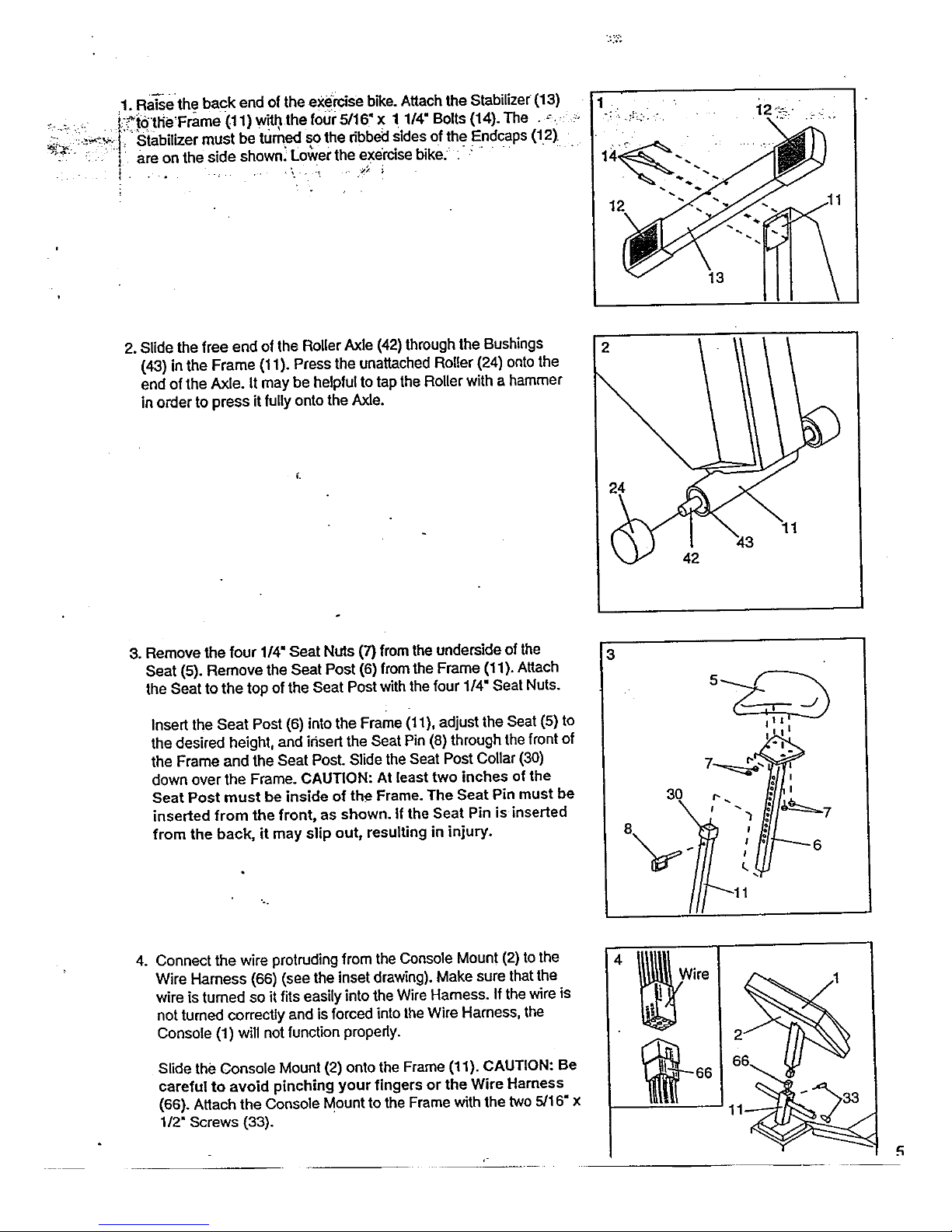
,1_Ra_sethe back end of the eX_mise bike. Attach the Stabilizer (13)
_. ,..:: i;-_i0'tlie'Frame (11) with the foul: 5/16 x 1 1/4 Bolts (14).The .,-, ,!:.
_:: :-;_'_:'_i_ _Siabilizer must be tt_med so the ribbedSides of the Endcaps (12).
"_:_ • _ are on the stde shown! Lo_et the exercise bike. : : .... " "
I " " '..... '/!
i
13
2. Slide the free end of the Roller Axle (42) through the Bushings
(43) in the Frame (11). Press the unattached Roller (24) onto the
end of the Axle. It may be helpful to tap the Roller with a hammer
in o,'der to press it fully onto the Axle.
2
24
42
11
3. Remove the four 1/4" Seat Nuts (7) from the underside of the
Seat (5). Remove the Seat Post (6) fromthe Frame (11). Attach
the Beat to the top of the Seat Post with the four 1/4" Seat Nuts.
Insert the Seat Post (6) into the Frame it 1), adjust the Seat (5) to
the desired height, and ir_sertthe Seat Pin (8) through the front of
the Frame and the Seat Post. Slide the Seat Post Collar (30)
down over the Frame. CAUTION: At least two inches of the
Seat Post must be inside of the Frame. The Seat Pin must be
inserted from the front, as shown. If the Seat Pin is inserted
from the back, it may slip out, resulting in injury.
3
6
4.
Connect the wire protruding from the Console Mount (2) to the
Wire Harness (66) (see the inset drawing). Make sure that the
wire is turned so it fits easily into the Wire Harness. If the wire is
not turned correctly and is forced into lhe Wire Harness, the
Console (1) will not function properly.
Slide the Console Mount (2) onto the Frame (11). CAUTION: Be
careful to avoid pinching your fingers or the Wire Harness
(66). Attach the Console Mount to the Frame with the two 5/16" x
1/;_"Screws (33).
Wire
R
 Loading...