


INDEPENDENT STEPPING ACTION • MOTIVATIONAL ELECTRONICS


OWNER'S MANUAL
CAUTION: Read all safety precautions and instructions in this manual carefully before using this equipment. Save this manual for future reference.
SOLD BY SEARS, ROEBUCK AND CO., CHICAGO, IL 60684
PATENT PENDING
IMPORTANT SAFETY PRECAUTIONS
- 1. Position the stepper on a level surface. Do not use the stepper outdoors or near water.
- 2. Plug in the power cord and turn on the power before using the stepper, or the stepper could be damaged. Place the power cord away from walkways or heated surfaces. Do not use the stepper if the power cord is damaged. Do not use an extension cord.
- 3. Wear suitable exercise attire, including athletic shoes, when using the stepper.
- 4. Keep your hands away from the pedals, chains and link arms during use. Keep smail children away from the stepper during use.
- 5. The pulse earclip is not a medical device. Various factors, including the user's movement while exercising, may affect the accuracy of heart rate readings. The earclip is intended only as an exercise aid in determining heart rate trends in general.
- 6. Use the stepper only as described in this manual. Servicing other than the procedures described in this manual should be performed only by an authorized service representative.
WARNING: Before beginning this or any exercise program, consult your physician. This is especially important for individuals over the age of 35 or persons with pre-existing health problems. Read all instructions before using. Sears assumes no responsibility for personal injury or property damage sustained by or through the use of this product.
BEFORE YOU BEGIN
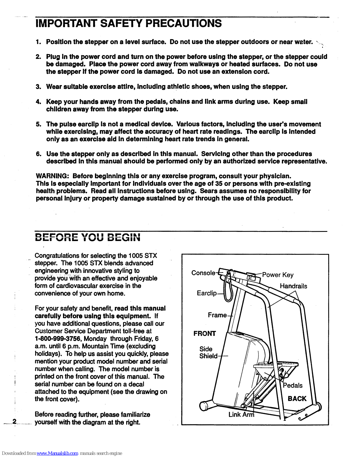
Congratulations for selecting the 1005 STX stepper. The 1005 STX blends advanced engineering with innovative styling to provide you with an effective and enjoyable form of cardiovascular exercise in the convenience of your own home.
For your safety and benefit, read this manuai carefully before using this equipment. If you have additional questions, please call our Customer Service Department toll-free at 1-800-999-3756, Monday through Friday, 6 a.m. until 6 p.m. Mountain Time (excluding holidays). To help us assist you quickly, please mention your product model number and serial number when calling. The model number is printed on the front cover of this manual. The serial number can be found on a decal attached to the equipment (see the drawing on the front cover).
Before reading further, please familiarize yourself with the diagram at the right.

2
ASSEMBLY
Remove all parts from the packing carton. Make sure that all parts are included before disposing of the packing materials. Read each step carefully before beginning. Assembly can be completed using the allen wrench included and your own adjustable wrench.
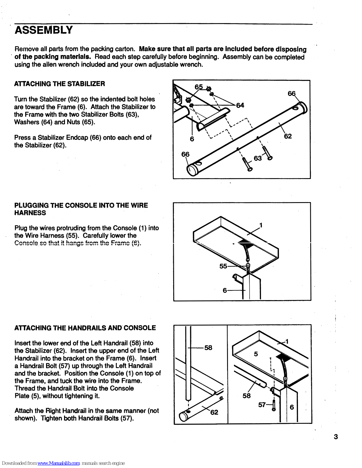
ATTACHING THE STABILIZER
Turn the Stabilizer (62) so the indented bolt holes are toward the Frame (6). Attach the Stabilizer to the Frame with the two Stabilizer Bolts (63), Washers (64) and Nuts (65).
Press a Stabilizer Endcap (66) onto each end of the Stabilizer (62).

PLUGGING THE CONSOLE INTO THE WIRE HARNESS
Plug the wires protruding from the Console (1) into the Wire Harness (55). Carefully lower the Console so that it hangs from the Frame (6).

ATTACHING THE HANDRAILS AND CONSOLE
Insert the lower end of the Left Handrail (58) into the Stabilizer (62). Insert the upper end of the Left Handrail into the bracket on the Frame (6). Insert a Handrail Bolt (57) up through the Left Handrail and the bracket. Position the Console (1) on top of the Frame, and tuck the wire into the Frame. Thread the Handrail Bolt into the Console Plate (5), without tightening it.
Attach the Right Handrail in the same manner (not shown). Tighten both Handrail Bolts (57).

PLUGGING IN THE POWER CORD
Plug the Power Cord (52) into the power jack at the front of the stepper.

MAINTENANCE AND TROUBLE-SHOOTING
Inspect and tighten all parts of the stepper regularly. Be sure that the cotter pins are securely attached to the clevis pins in the pedals. Outside surfaces can be cleaned using a soft cloth and mild, non-abrasive detergent. Do not allow liquids to come in contact with the console.
If the pulse earclip does not function properly, the earclip should be cleaned. Press the earclip open, and wipe the small bubbles inside the earclip, using a cotton swab saturated with denatured alcohol.
If the range of stepping resistance is too high or too low, the range can be adjusted. Remove the screws from the bottom of the side shields. Carefully pry the bottom of the side shields apart, until the side shields can be lifted off the frame. Locate the tension buckle on the underside of the frame. To raise the range of resistance, open the tension buckle, pull the resistance strap slightly tighter and close the buckle firmly. To lower the range of resistance, loosen the resistance strap slightly. Replace the side shields, and reattach the side shields with the screws.
The axles to which the link arms are attached should be oiled every six months, or whenever the joints become noisy. Apply a few drops of light, multi-purpose oil at the locations indicated in the drawing.


The clevis pins in the pedals should be greased every six months, or whenever the pedals become noisy. Remove the cotter pins from the clevis pins, and slide the clevis pins out of the pedals. Apply grease to the clevis pins, and reattach the pedals.

STEPPER OPERATION
Plug the transformer on the power cord into a 120-volt outlet. Keep the power cord away from walkways and heated surfaces. Turn on the power when using the stepper, or the stepper could be damaged.

5
STEPPER OPERATION
Hold the handrails with an overhand grip, and step onto the pedals. Begin stepping, alternately pressing the right and left pedals down with a smooth, rhythmic motion. Because the pedals move independently, it is important to maintain a continuous motion. Adjust the stepping resistance until you can comfortably maintain a continuous motion. (See MANUAL RESISTANCE MODE on page 6.) IMPORTANT: Never allow the pedals to hit the floor.
As you step, you can exercise the upper leg muscles by keeping your feet flat on the pedals. To focus on the calf muscles, rise on your toes as you step. Whether standing erect or leaning forward slightly, always keep your back straight in order to avoid injury. For the best aerobic workout, exercise physiologists recommend taking relatively short, rapid steps.
DIAGRAM OF THE CONSOLE
Please read all instructions carefully before operating the console.

DESCRIPTION OF THE CONTROLS
TRACK FOUR PROGRAM BUTTON- This button switches the console to the program mode. The program indicator will light when the console is in the program mode.
SET BUTTONS- These buttons are used to select programs, enter your weight into the console, and set time and distance goals.
MODE BUTTON- This button is used to select monitor modes.
START/PAUSE BUTTON- This button starts and stops the console. The mode indicators will flash when the console is stopped.
RESISTANCE DIAL- This dial is used to control the stepping resistance, and to select a fitness level for programs.
TURNING ON THE POWER
insert the power key into the slot in the front of the console. Wait for at least 3 seconds before operating the console.
MANUAL RESISTANCE MODE
When the power is turned on, the console will be in the manual mode. As you exercise, the stepping resistance can be controlled by turning the resistance dial. As the dial is turned clockwise, toward "max," the resistance will decrease and your stepping speed will increase. As the dial is turned counterclockwise, toward "min," the resistance will increase and your stepping speed will decrease. Adjust the resistance until you can maintain a smooth, continuous stepping motion.
Downloaded from www.Manualslib.com manuals search engine
PROGRAM MODE
In the program mode, preset programs will control the stepping resistance automatically, leaving you free to concentrate on your workout. Four different programs are offered. You can choose how long the programs will last, and adjust the programs for your individual fitness level.
Each program consists of eight equal time periods, or "segments." The stepping resistance will change automatically at the beginning of each segment. The four graphs (labeled P1-P4) on the console show how your stepping speed will change during each program. During program 1, for example, your stepping speed will gradually increase, and then gradually decrease. During program 4, your stepping speed will alternately increase and decrease.
To switch the console to the program mode, press the TRACK FOUR PROGRAM button. The program indicator and the eight segment indicators will light. To select one of the four programs, press either of the SET buttons. A "P1," " P2," " P3" or "P4" will appear on the main display to show which program you have selected. Next, select a "fitness level" for the program by turning the resistance dial clockwise. The farther the dial is turned, the more challenging the program will be.
All programs are preset to last for 16 minutes (each segment will last for 2 minutes). If you want to change the length of time the program will last, first press the MODE button until the TIME/SET indicator lights. (Be sure the SCAN indicator is not lighted also.) Press the SET buttons to set the length of time you want the program to last. Each time one of the buttons is pressed, the length of time displayed will change by 10 seconds. The program must be set for at least 4 minutes.
When you are ready to start the program, press the START/PAUSE button and begin stepping. The first segment indicator will flash to show that the first segment of the program has started, and the stepping resistance will automatically adjust to the first setting. When only 10 seconds remain in the first segment, the time will be counted down on the main display. When the first segment is completed, the second segment indicator will flash, and the stepping resistance will adjust to the second segment indicator will flash, and the stepping resistance will adjust to the second setting. The program will continue in this manner until all eight segments are completed. If you need to stop the program before the program has ended, press the START/PAUSE button. To restart the program, press the START/PAUSE button again.
To switch the console to the manual mode, press the TRACK FOUR PROGRAM button.
SELECTING MONITOR MODES
The console features eight monitor modes to give you instant feedback as you exercise. When the power is turned on, the SCAN mode will be selected automatically. In the SCAN mode, the TIME/SET, DISTANCE/SET, SPEED, CALORIES, PULSE and SEGMENT TIME modes will be displayed in a repeating cycle. (Note: The PULSE mode will be displayed only if the pulse earchip is worn [see PULSE below]. The SEGMENT TIME mode will be displayed only if the console is in the program mode.) Individual modes can be selected by pressing the MODE button. Indicators will light to show which mode you have selected. The main display can be reset to zero, if desired, by removing the power key and then re-inserting it. The eight modes are described below:
SCAN: This mode automatically displays all other modes, except WEIGHT, in a repeating cycle. Note: The PULSE mode will be displayed only if the pulse earclip is worn. The SEGMENT TIME mode will be displayed only if the console is in the program mode.
WEIGHT: Before selecting the CALORIES mode, your weight should be entered into the console. Select the WEIGHT mode, and press the SET buttons to enter your weight, in pounds. Each time one of the buttons is pressed, the weight displayed will change by 5 pounds. The buttons can be held down to enter your weight quickly.
7 .:
TIME/SET: This mode displays the elapsed time. This mode also allows time goals to be set. To set a time goal, first select the TIME/SET mode. (A goal cannot be set while the SCAN mode is selected.) Press the SET buttons to enter the length of time you plan to exercise. Each time one of the buttons is pressed, the time displayed will change by 10 seconds. The buttons can be held down to enter the length of time will be counted down.
DISTANCE/SET: This mode displays the total number of steps you have completed. This mode also allows distance goals to be set. To set a distance goal, first select the DISTANCE/SET mode. (A goal cannot be set while the SCAN mode is selected.) Press the SET buttons to enter the total number of steps you plan to complete. Each time one of the buttons is pressed, the number displayed will change by 1 step. The buttons can be held down to enter the number quickly. As you exercise, the steps will be counted down.
SPEED: This mode displays your current stepping pace, in steps per minute.
CALORIE: This mode displays the number of Calories you have burned. For an accurate count, first select the WEIGHT SET mode, and enter your weight into the console.
PULSE: This mode displays your heart rate during your workout (your heart rate must be higher than 70 beats per minute to be displayed). Plug the pulse earclip into the jack on the console, and attach the earclip to your left ear lobe. Slide the clothes clip onto your collar to prevent excessive movement of the earclip wire. Note: If your heart rate is not displayed after a few seconds, try rubbing your ear lobe and repositioning the earclip. The pulse earclip is not a medically-certified device. External factors such as movement may affect the accuracy of heart rate readings.
SEGMENT TIME: When the console is in the program mode, this mode displays the time remaining in the current program segment. Note: Even if this mode is not selected, the time remaining will be displayed during the last ten seconds of each segment.
TURNING OFF THE POWER
Remove the power key from the console. The key can be stored in a secure location to prevent unauthorized persons from turning on the power.
0
CONDITIONING GUIDELINES
The following guidelines will help you to outline a personal fitness program. Remember that adequate rest and good nutrition are essential to the success of any fitness program. Before beginning this or any exercise program, consult your physician.
EXERCISE INTENSITY
To maximize the benefits of exercising, your level of exertion must exceed mild demands, while falling short of causing breathlessness and fatigue. The proper level of exertion can be found using the heart rate as a guide. For effective aerobic exercise, your heart rate must be maintained at a level between 70% and 85% of your maximum heart rate. This is called your "training zone." You can determine your training zone by consulting the table below. Training zones are given for both conditioned and unconditioned persons according to age. Find the column that is appropriate for you.
| AGE |
UNCONDITIONED
TRAINING ZONE (BEATS/MIN) |
CONDITIONED
TRAINING ZONE (BEATS/MIN) |
AGE |
UNCONDITIONED
TRAINING ZONE (BEATS/MIN) |
CONDITIONED
TRAINING ZONE (BEATS/MIN) |
|---|---|---|---|---|---|
| 20 | 138-167 | 133-162 | 55 | 127-155 | 122-149 |
| 25 | 136-166 | 132-160 | 60 | 126-153 | 121-147 |
| 30 | 135-164 | 130-158 | 65 | 125-151 | 119-145 |
| 35 | 134-162 | 129-156 | 70 | 123-150 | 118-144 |
| 40 | 132-161 | 127-155 | 75 | 122-147 | 117-142 |
| 45 | 131-159 | 125-153 | 80 | 120-146 | 115-140 |
| 50 | 129-156 | 124-150 | 85 | 118-144 | 114-139 |
During the first few weeks of your exercise program, keep your heart rate near the low end of your training zone. Over the course of a few months, gradually increase your heart rate until it is near the high end of your training zone. You can find your heart rate using the pulse mode of the console. Exercise for at least four minutes, and then measure your heart rate. If your heart rate is above your training zone, decrease your level of exertion. If your heart rate is too low, increase your level of exertion.
WORKOUT GUIDELINES
Each workout should consist of three basic parts: a warm-up, 20-30 minutes of training zone exercise, and a cool-down. Warming up prepares the body for strenuous exercise by increasing circulation, delivering more oxygen to the muscles and raising the body temperature. 5-10 minutes of stretching or light calisthenics will provide a good warm-up. After warming up, begin exercising at a light pace. After a few minutes, increase the intensity of your exercise to raise your heart rate to your training zone for 20-30 minutes. Always end your workouts with 5-10 minutes of stretching to cool down. This will help to offset muscle contractions and other problems caused when you stop exercising suddenly.
To maintain or improve your condition, you must work out 2-3 times per week following the pattern described above. A day of rest between workouts is recommended. After several months of exercise, the number of workouts can be increased to 4-5 per week. The key to success is CONSISTENCY.
PART LIST- Model No. 831.285902
|
Key
No. |
Reorder
No. |
Qty. | Description |
Key
No. |
Reorder
No. |
Qty. | Description |
|---|---|---|---|---|---|---|---|
| 1 | 105620 | 1 | Console | 36 | 100498 | 1 | Magnet |
| 2 | 101508 | 1 | Pulse Earclip | 37 | 101575 | 4 | Master Link |
| 3 | 100933 | 1 | Power Key | 38 | 107147 | 2 | Pedal Arm |
| 4 | 013423 | 6 | Screw | 39 | 100048 | 8 | Pedal Arm Bushing |
| 5 | 106151 | 1 | Console Plate | 40 | 103735 | 2 | Pedal Arm Pushnut |
| 6 | NSP | 1 | Frame | 41 | 105101 | 2 | Pedal Arm Spacer |
| 7 | 050001 | 1 | Tension Buckle | 42 | 107151 | 2 | Link Arm |
| 8 | 105433 | 2 | Large Bumper | 43 | 103677 | 4 | Link Arm Bushing |
| 9 | 106750 | 1 | Resistance Strap | 44 | 100150 | 4 | Link Arm Pushnut |
| 10 | 103909 | 1 | Spring Assembly | 45 | 105865 | 2 | Clevis Pin |
| 11 | 101042 | 1 | Tension Rope | 46 | 106911 | 2 | Cotter Pin |
| 12 | 103888 | 1. | Tension Motor | 47 | 107145 | 1 | Left Pedal |
| 13 | 101049 | 2 | Tension Motor Screw | 48 | 107146 | 1 | Right Pedal |
| 14 | 054024 | 2 | Snap Ring | 49 | 107148 | 2 | Pedal Foot Pad |
| 15 | 014170 | 2 | Large Washer | 50 | 101577 | 1 | Power Plug Screw |
| 16 | 101570 | 2 | Sprocket Key | 51 | 103957 | 2 | Spring Wheel Pushnut |
| 17 | 106153 | 2 | Small Sprocket | 52 | 106595 | 1 | Power Cord |
| 18 | 103859 | 1 | Small Washer | 53 | 106113 | 1 | Voltage Meter |
| 19 | 105114 | 1 | Large Sprocket | 54 | 101743 | 1 | Reed Switch |
| 20 | 105102 | 1 | Large Sprocket Chain | 55 | 106132 | 1 | Wire Harness |
| 21 | 102040 | 1 | Sprocket Spacer Cup | 56 | 105825 | 2 | Small Bumper |
| 22 | 101565 | 2 | Sprocket Bearing | 57 | 013561 | 2 | Handrail Bolt |
| 23 | 105095 | 1 | Spacer | 58 | 107176 | 1 | Left Handrail |
| 24 | 105674 | 1 | Flywheel Washer | 59 | 107162 | 1 | Right Handrail |
| 25 | 101980 | 2 | Thin Nut | 60 | 102856 | 2 | Handrail Foam |
| 26 | 014004 | 2 | Beveled Washer | 61 | 013162 | 8 | Mounting Screw |
| 27 | 102357 | 1 | Flywheel Axle | 62 | 105098 | ⇒ 1 ` | Stabilizer |
| 28 | 102356 | 2 | Flywheel Bearing | 63 | 013207 | 2 | Stabilizer Bolt |
| 29 | 104 0 08 | 1 | Flywheel Sprocket | 64 | 014041 | 2 | Stabilizer Washer |
| 30 | 10 7150 | 1 | Flywheel | 65 | 012082 | 2 | Stabilizer Nut |
| 31 | 104478 | 2 | Washer | 66 | 040134 | - 4 | Stabilizer Endcap |
| 32 | 012175 | 2 | Thick Nut | 67 | 104911 | 1 | Left Side Shield |
| 33 | 107049 | 2 | Large Chain | (68) | 107370 | З | Side Shield Bolt |
| 34 | 104475 | 2 | Spring | (69) | 103762 | 3 | Side Shield Nut |
| 35 | 107149 | 2 | Spring Wheel | 70 | 104910 | 1 | Right Side Shield |
Note: "#" indicates a non-illustrated part. Specifications are subject to change without notice. See the back cover of this manual for information about ordering replacement parts.
10
Rev. 2/92


 Loading...