

Page 1
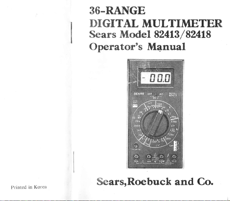
36.RA]\[GE
Printed
in Korea
DIGITAL
Sears Model 82413
MULTIMETER
/
Operator's M4nual
SearsrRoebuck
and
52418
Co.
Page 2

MULTIMETER
I.
information
this
READ
WARNINGS
CAUTIONS
SAFETY
denote
denote
RULES
1{arning
This tester
However,
use. Electrical
lack
of
the
Read
Read this Instruction
Voltages and
ment with
instructions
understand the
use this tester.
has been designed
no design can
ci.rcuits can
caution or
Manual
this test
in this manual
Do not exceed the
poor
currents within
general
Safety Check
check the
Double
making measutements.
before
instruc tions?
Disconnect the tester
changing
switclr is in any
inscrt in correct fuse
switch positions.
Do not
Whcn rcplacing
connect to circuits
ohms or
SAFETY
using thc
before
hazards to
hazards
equipment
fuses use only
notd"j.,,
thc opcrntor'
to the
completely
be dangerous
practices arc
safety
Manual
can be
for every
instructions
switch
setting,
Are
or
current
_
tnctcr
mctcr.
yorrr
with
protcct .il',.rirrst
rtrcl/r,r
carefully rntl
the capabillty
hazartlotts.
meastlrclrlc
beforc
limits
of
and
you
following
off the
turn
voltage
with
position.
specificd
itt trrind.
s.tlclt
trst ti.
rrr(
l.tlr.rl
(,r'tcct
rvltcn
.,rrrplr'tt'ly.
ol trtt.isLtfc-
1,,11,,t'tlrc
l{t .rtl rrttd
lrt
attclrrptirrll
tllc tcstcr,
lcad connections
all of the
power before
present when
fuses
type
and
Don't
Touch
Don't
touch
parts
of
first for
Turn
probes
to it. Be
touch
the
Do
not use
High
Voltage
Always
Be sure
nections
Don't
circuit
while it is
Before
wait for
the
Distribution
tt,
and
In
high
bus bars,
the circuit
high
energy
current
_range,
is
virtually
Special
is
available.
attempting
circuit.
SAFETY
exposed
an electrical
voltage
before
off the power
circuit.
cracked
is
start
with
there
to
the
circuit.
touch
the
disconnecting
meter
Circuits
energy
dangerous
is shorted.
circuit
or
any other
shorted.
equipment
Conract
to
make
rS
No ACCIpENT
wiring,
circuit,
touching
to
sure
there is
or broken
Dangerous
the power
is no
voltage
tester,
on.
the
to return
Pack
circuits
arcs
If
when
designed
qualified
a
measurements
connections
If in
it.
a circuit
no
voltage present
off,
present
its
test leads,
tester,
to
"zero.,,
Punch
a
such
as distribution
of explosive
the
tester
set
to
a 1ow
low
impedance
for
person
doubt,
before
test leads,
before
turn
the
nature
is
connected
resistance
use
with
for
on
or other
check
connectins
or any part
circuit
range,
assistance
any high
the
circuit
beforJ you
making
of
offand
transform.ers
can
occur
across
range,
the
circuit
these
circuits
before
energy
,,live,,
resr
con-
the
if
a
a
-2-
Page 3
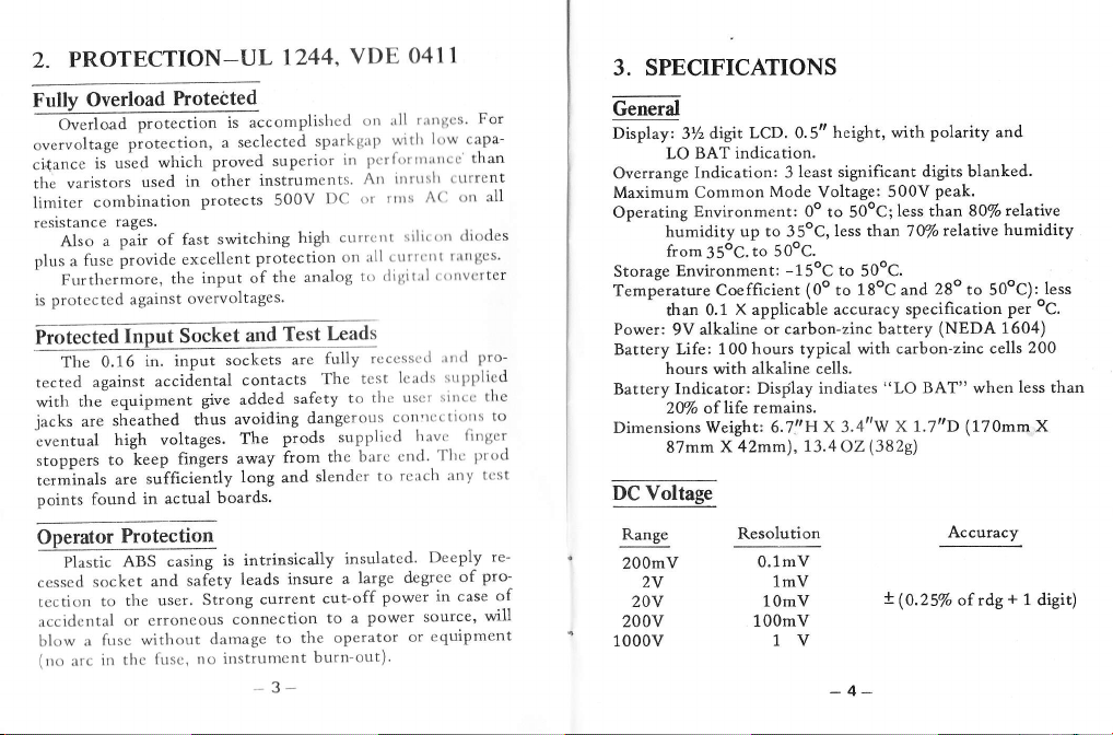
PROTECTION-UL
2.
Overload
Fully
-
Ot*l..d
overvoltage
is-used
cidance
the varistors
combination
limiter
resistance
Al.o
plus
is
"
fuse
a
Furthermore,
protccted
Frotected
0.16
The
against
tected
the
with
jacks
are
-eventual
stoppers
t"r-in"ls
points found
Operator
pt"tri"
socket
cessed
to
tcction
accidcntal
fusc without
a
blow
(rrt,
in rlre
:rrc
hotected
protection
protection'
which
in other
used
rages.
pair of
provide
against
fast
excellent
the
overvoltages.
Inpuf Socket
in. input
accidental
equipment
sheathed
thus
high voltages.
sufficiently
are
fingers away
to k""p
in actual
Protection
casing
,ASS
safety
and
user.
the
erroneous
or
frts.
,
1244,
is accomplishcd
seclected
a
superior
proved
instrumcnts
protects
input of
500V
switching
protection
the
and
sockets
Test
are
contacts
avoiding
prods
The
safety
give added
from
long
and
boards.
intrinsically
is
leads insure
current
Strong
connection
to
damage
tlo itlstrultt.'nt
3-
VDE
sparkgap
in
DC
cttrrcrrt
high
on
analog
Lrads
fully
The
to
dangerous
supplicd
the
slendcr
insulated'
a
cut-off
to a
operator
the
burn-out)'
O4I1
t;trtllcs
orr rrll
Art ilrrrrslr
or lttrs
to
tcst
barc
large
low
A(l
siltc()rr
ttt
I
'ttrrl
sitrt.
havc.
'Ilr(:
Deeply
degrce
in case
capa-
(
tlrrcnt
trrt all
(li()des
rrtrtgcs'
()trvcrtcr
srtpl>licd
lirtgcr
:tny tt:st
of
witlr
pcrlirrtttrtrrcc'than
ttttt
rll
'
ililiitrrl
rcccsse'l
lcarls
tltc usct
corl'rfcti()rrs
cnd'
rcach
to
power
power source,
or equipment
For
pro-
the
l)r'od
pro-
will
3. SPECIFICATIONS
Geneil
oi"pt"y, ZUdigit
LO BAT
Overrange
Maximum Common
Operating
humidity up to 35oC,
from35oC.to 5OoC.
Environment:
Storage
Temperature Coefficient
than 0.1
Power:
9V
Battery Life:
hours with alkaline
Battery Indicator:
to
re-
clf
2Mo
Dimensions Weight:
87mm
DC
Voltage
Range
200mV
2V
20v
200v
1000v
LcD. 0.5tt
indication.
Indication: 3
Environment: 0o to
alkaline or
100 hours typical with
of life
least significant digits
Mode
Voltage: 500V
-15oC
X applicable accuracy
(0o
carbon-zinc battery
cells.
Display indiates
remains.
6.7'.'Hx 3.4"'w
X 42mm),
Resolution
13.4
0.1mV
1mV
1OmV
10OmV
1V
with polarity and
height,
50oC;less
less than 70%
to
50oC.
L8oC
to
and
specification
carbon-zinc cells
BAT" when
"LO
1.7t'D (17Omm
x
(3829)
O2
x
(0.25%
peak.
than
relative
28o to
(NEDA
Accuracy
of rdg
blanked.
S}Vorelat\ve
humidity
50oC):
per
1604)
200
Iess than
+
1
less
oC.
X
digit)
Page 4
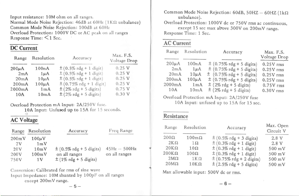
Input resistance:
Mode
Normal
Common
Overload
10M
ohm on all
Noise Rejection: 46dB at 60Hz
Mode Noise Rejection: 100dB
Protection: 1000V DC
ResponseTime:(1Sec.
qqlsqeq
Range Resolution
zmA
100nA
100pA
Protection
Input:
10A
lp.A
10pA
1mA
10mA
200p4
20mA
200mA
200OmA
10A
Overload
AC Voltage
Range Resolution
200mV
100p.V
2V 1mV
20V 1OmV
200V 100mV on all
750V lV
Convcrsion:
lnput Impedance:
Calibrated for
cxcept
200mV
!(O.5%
!(0.5%
!(0.5%
+(0.75%
+(2%rdg+5digits)
+(2%rdg+5digits)
mA Input:
Unfused up to
!
(0.5% rdg
+
(l%
10M shunted
trnt"._
or AC
Accuracy
rdg
rdg
rdg+
2Al250Y
Acctrracy
ranges
+
ds
rms
of
by 100pF
_
U
ranges.
peak on
+
1 digit)
+
1
digir)
1 digit)
l disit)
rdg+
for 1
15A
+
5 digits)
5 disits)
sine wave
(1KO
60llz
at
fuc.
sccortds.
5
45Hz
on all
on all ranges
unbalance)
r:rnges
rll
Max. F.S.
Voltage Drop
0.25
V
0.25
V
0.25 V
0.25 V
0.75 V
0.30 v
Freq Range
500H2
-
ranges
Common
Overload Protection:
Resoonse
Mode
unbalance).
except 15
Time:
Noise
sec max
1 Sec.
AC Current
Range
200p"4
200mA
2000mA
Overload Protection
Resistance
Resolution
2mA
20mA
10A
10A
100nA
1pA
1OpA
10OpA
lmA
10mA
Input:
unfused up to 15A for
Range Resolution
2004
2KA
20KO
200Ka
2Ms}
20Mo
Max
100mO
ls}
10sl
1000
1KO
10KO
aliowable input:
Rejection:
1000V
x
(0.7
!
(0.7
+
(0.75%
!
(0.75Vo
t
Q%
+
(2%rdg+
mA Input: 24/250V
!
x(0.3%
x
!
X
!
500V dc
dc or
above
Accuracy
5%
5% rdg
rae
(0.5%
(0.3%
(0.3%
(0.75Vo
(2.5%
60d8,
750V rms
300V on
+
rdg
5 digits)
+
5 digits)
+
rdg
5 digits)
+
rdg
digits)
5
+
digits)
5
digits)
5
Accuracy
+
rdg
3 digits) 2.8 v
rdg+
1
+
rdg
1
+
rdg
1
+
rdg
2 digits)
+
rdg
5 digits)
rms.
or
-6-
5OHZ
-
ac continuous,
200mV
fuse
15
sec.
digit)
digit) 500
(1kS,
60HZ
range,
Max. F.S.
Voltage Drop
0.25V rms
0.25V rms
0.25V
rms
0.25V
rms
0.75V rms
0.30V rms
Max,
Open
Circuit V
2,8v
mV
digit) 500 mV
mV
500
mV
500
Page 5

Continui9Test
Resistance range: Btzzer sounds
200O
Resoonse
Diode Test
Test
Maximum
time: Less than
voltage: 2.8
test
('ttl
approximately.
(
-t<-
)
Volts
current: 3m
)
100 m Sec.
Ampcres,
Temperature Measurement
Range Re solution
OoF ro 2000oF 1oF
Sensor; type
Conductance
Range
200nS
K (NiCr-NiAI)
Measurement
Resolution
0.1nS
Capacitance Measurement
Range
2000pF
2uF
20uF
hFE
Test
i"rt.orditior :
hFE gain
0
1000 (NPN.
-
Resolution
1pF
0.001uF
0.01uF
1OuA
2.8V
PNP)
-7-
with rcsistances less
Accuracy
+
+
(50
2 aigitr; ,p to ZZSof
!
of rdg ovcr 2250F
3%
Accuracy
t(7.5%
rdg + 10 digits)
Accuracy
!(r.s%F.S.+5disits)
!(z7oP.s.
+
(2Vo F.s.
+
5 digits)
+
5 digits)
than
4. OPERATING
General
The
Sears
high
level
engineer,
sturment
Equipped
position
the
single
cases
and
instruments
duction.
apprlcatlons.
Model
3-112
dig:^t
technician,
that
is
accurate,
with nine functions
is quickly
selector
equippid
is
equally
testing,
field
wffi;s
T.
fo
instrument,
500V
2. Before
nectors,
insulation.
DC
Voltage
1.
Connect
black
2.
Slide
position).
3. Set
of Value
factor
untill
electrical
^-la
above
the
and
do not
earth
use
prodg
Measurement
red
test lead
to
"COM".
the POWER/FUNCTION
RA,NGE
switch
not
only for
is
not
known,
satisfactory
INSTRUCTIONS
82413182418
multimeter
and hobbyist
reliable
and
easily
switch.
-*'rth
a multi-position
suited
servicing,
shock hazard
measure
sround.
oiinstrument,
for
cracks,
to
desired
this functioniut
set switch
reading
and
and
selected
Smail
enough
for
and industriJl
voltages
breaks,
,,V,A",
to
,,V',
to highest
is
obtained.
designed
design
switch
is
completely
who
always
36 ranges,
with
a simple
to
tilt stand.
engineering,
and/or
that mighl
inspect
or
any defects
input
to
position.
"ru
portable,
for
use
demands
ready
each
fit in
mainienance
damage
test
leads,
connector
,,DC
O,'
If
magnitude
-""r.r1"rn"rr,
range
and reduce
by
the
an
for
use.
test
rurn
attache
This
pro-
to
exceed
con-
in
and
(mid
in-
of
the
the
Page 6

4.
Connect test
Turn
5.
Voltage value wili appear on Digital
the voltage
DC
Current
1.. Red lead
Black
For measuremenb between 2 Amps
lead
red
)
POWER/FUNCTION switch to
switch
J.
Open the circuit to be measured, and
leads
power
on
polarity.
Measurement
to
"mA"
lead
to
to
"l0A"
to desired
to device or circuit
to
device or
jack
for measurcrncr)ts rrp to 2
jack.
"COM"
jack.
position.
"A''
bcing measured.
circuit bcing measured.
Display
and
"I)C
IN SERIES with the ioad in which currcnt
measured.
Read current value on
AC Voltage
Red lead
L.
Measurements
to
"V-s}",
2. POWER/FUNCTION switch to
to desired
Read voltage vaiue on
3.
Resistance Measurements
1.
Red
POWER/FUNCTION
2.
switch to desired
lead
"V"
to
"V.
Digital Display.
Black lead
position.
Digital Display.
f,}", Black lead to
switch to "DC
"OHM"
position.
to
"AC",
"COM".
"COM".
and
s2",
aiong with
l0
Amps, connect
()",
rnd
conncct test
is to
RANGE switch
and RANGE
Amps,
RANGE
leads
be
If
3.
the resistance
turn
off power
applying
4.
Connect
q
Read
resisrance
Diode
Tests
L.
Red
lead
2.
POWER/FUNCTION
switch
3, Ifthe
,
4.
5. In
to the
semiconductorjunction
to
circuit,
a
Connect
case
of
to,
cathode)
under
_test
is
displayed.
When
the
cathode,
defective,
Continuity
1.
Red
lead
2. POWER/FUNCTION
switch
Connect
Built-in
tinuous.
to Btzzer
buzzer
3.
4.
prods,
test
test leads
,,V.f,)',,
to
2K,e (
turn
leads
test
connection
good
a
is defective,
test leads
Black
to
"000"
Checks
,,V.
ro
o,',
test leads
sounds
being
value
or
(
measured.is
and
discharge
to
circuit
on Digital
Black
switch
+<-
off power
to
device.
of forward (Red
diode shows
"000,' (shorted),
are
anode),
a good
other
figures
Black
lead
switch
,r|)
position.
)
to
the
circuit
if
the
connected
all
being
measured.
Display.
,,COM".
iead
to
,.DC
to
position.
)
being
measured
and
discharge
a value.
connected
diode
are
to be
,,COM,,.
to
,,DC
to
under
circuit
capacitors
0,',,
and
all
to
anode,
If
o,
reverse
shows
displaved.
A"
and
,
test.
under
to
a circuit,
RANGE
is
connected
capacitors.
the
,,1,,
(opend)
(Red
,,1i'.
RANGE
test
is con_
before
Black
diode
Ifit
to
is
-9-
Page 7

-"t"t
connecting
by
and
exceed
more
..V.
A"
to "TEMP"
place
to be
from the
meter
when
display
can be
,,coM"
150V
l0 seconds)
than
and "COM"
protective
the
probe
tihe
measured
is designed
thermocouple
a
will
Neasyrenebt
th"
ments
,,v.o,,,
Do not
(no
the
POWER/FUNCTION
switch
Remove
couple
material
directly
"F).
r
The
lly
the
connected.
Conductance
@leadto"coM".
POWER/FUNCTION
2.
switch
to
"S =
o
for making
used
tempelature
the
jack.
continuously
avoid
to
jack
instrument.
or
to
switch
position.
or
display.
to
show "1" when
switch
1
"
"DC
tube
plastic
thermocouple
take the
and
The reading
show temperature
plugged
is
to
"DC
temperature
(included)
probe
or 300V
any
momentary
dannge between
and
o"
,
the thermo-
from
on or
tip
temperature
is in
into the
no
thermocouple
O"
and
,
measure-
to
RANGE
the
in
reading
Fahrenheit
automatica-
jack'
but
RANGE
DisPlaY'
-oh;
=
formerly
is
If resistance
I by the
10,000M
leakage
etc.
x 1010
0.1 X
=
the
=
known
in terms cif
t""Jo"i,
measurement
mngp
capability
ohm where
measurement
cables,
In all cases
0.1
X
=
result
loro
leads to
test
Digital
SIMENS
S;
ductance
B. The
(10-95).
nS
can divide
conductance
Use
The S
resistance
point
up to
provide
ponents,
6oards
DC.
<5V
readout
conductance
measurement
useful
diodes,
(pcb's),
,l
q
I
Connect
value on
ral
r' A'
2.
I
Readout
is
)
I
I
ExamPle;
For
measurement
If the
is
J x toto
10"
measuring
point and
international
as
the
conductance
rcading
ft"ti-"rtdly
as
effectively
of this
it can
connectors,
1010
is 10,
l,oooM
=
the test
Resistance
=
the
read the
unit of
mho.
with
required,
is
by'i010'
leakage tester.
a
extends
DMM
used
be
variable
on
printed-
voltage
(ohm)
resistance
ohm
con-
unit
yo11
the
to the
to
com-
circuit
is
reading
Page 8

If
measurement
the
| .^
l0ro
x
,^*^
rvvv
Capacitance Measurement
1.
POIIVER/FUNCTION
switch
2. Before
to desired
measurement,
set
to zero,
connected
so that zero reads
with an open condition
to
CAP sockets, rurn
3. Connect capacitance
surement
the
4. Read
of polarized
CAP sockets,
capacitance
result is
=0.001
=l0Xl06ohm
l0M
=
switch
"CAP"
all capacitance
on display.
test leads
qondensers,
agree with those
vaiue on Digital Display.
Tt*rtrt- ttFE N{""."*-""t
1.
POWER/FUNCTTON
switch to
of
2. Insert pins
jnto
"PNP"
transistor.
ofemitter,
E.B.C. pin
3. Read the displayed
0 to 1000.
B"tt"ry
R"et"""-""t
Before
connect
hazard.
shock
attempting
test leads from
switch
or
"NPN"
base, and collector
socket
respectively.
value
lcAtrrroNl
battery removal
-
of transistor
any energized
13
1000
x1010
ohm
to
"DC
position.
without
the
"CAP
to condesser (For
have
of a condenser).
to
position
according
gain (hFE)
or rephcement, dis-
-
S|"
and Range
,
ranges should
condenser
a
ZERO ADJ"
polarities
the
and RANGE
,
to
ofthe transistor
between
circuits to
avoid
be
mea-
rype
1.
It
BAT"
scteen.
2. Slide the
Unsnap
3.
volt battery.
alkaline 9
battery
Piace
4.
fry-R"PbIgggtI-
1. This
protect
to 2000mA.
t
of
To
pressing it inward.
Replace blown
fire, do
than
Calibration
yourself. It
extremely accurate
complete and
instructions.
1. GENERAL
is
necessary
appears
battery
the battery
volt battery, although
is suitable.
the battery
instrument
current measuring
the
the fuse, slide the battery cover upward by
replace
not
use a
soecified.
We
1-1.
not recommend that
do
is a
you
Perform
74oF to
80oF
Allow instrument
at least 30 minutes.
to replace battery
in the upper
cover upward
connector and replace
For
maximum
when the
left
corner
it inward.
pressing
by
life use Sears
any standard 9 volt
covet in right
is provided
fuse
highly technicai procedure that
have such a power supply,
calibration
new
with
fuse
which
power supply. If
at
and a relative
to stabilize
14-
-
position.
with a 2Al250V
which measure
circuits
2Al250V
an
fuse. To
has
higher rated value
a
yorl
attempt
your
knowledge is
ambient temperature of
humidity
at
this
of 80% or
temperature
words
"LO
LCD
of the
new
with
DieHard
fuse to
prevent
calibration
requires
fol1ow these
9
up
an
less.
for
Page 9

Remove the rear
1-2.
moving three screws
DC
CAL
2-1. Slide
2-2.
2-3.
2-4.
AC CAL
3-1.
3-2. Set the output
POWER
the RANGE
Set the
connect it to the
tors
tiometer
Display reads
0.057o
500
output of the calibrator 1
of the instrument.
Using a small
VR1
Remove
Slide
the DC
POWER/FUNCTION
pwe
HZ,
and connect it to
input connectors
Adjust potentiometer
3-3.
reads
exactly 190.0.
CAPACITANCE CAL
cover
and then
FUNCTION switch
switch to 200mV
"V.A".
flat-tipped screw
(DC,
ADJ) until multimeter
190.0.
exactly
calibrator output
the AC calibrator
of
sine wave
at a
the mulrimeter.
of
VR2
4-1.2000pF
POWER/FUNCTION
Slide
RANGE
ZERO ADJ",
100pF standard
tur:n the VR3 so that 1000 reading
switch to 2000 p position, Turn
so that zero
capacitor to
_
15_
from
the instrument
lift
off the cover.
to
position.
and
switch to
"DC
9OmV
"COM"
inout
driver, adjust poten-
from
multimeter.
"AC".
for 190mV
frequency
the
switch to
reading on display.
'!V.d]"
(AC,
ADJ)
CAP test
on display.
between 45
until display
"DC
f,i"
!
0.02%
connec-
Digital
and
"COM"
O"
the
Connect
leads,
by re-
and
,
^nd
-
and
,
"CAP
and
4-2. 2uF
Set the RANGE
ZERO
"CAP
connect 1pF
VR6 so
4-3.
20ttF
Set the
"CAP
Connect 1OpF
and turn
TEMPERATURE
5.
standard
that 1,000
RANGE
ZERO
the VR5 so
ADJ"
ADJ" so
standard
CAL
Slide POWER/FUNCTION
RANGE
t
calibrator
the
until
Example:
switch to Temp
DC
to
and
"V'O"
display reads
"COM" input connectors.
ambient temperature
0,798mV
exactly
TO
switch
2p position,
so that zero
capacitor
reading
on display.
switch
20trr position,
to
thar zero
capacitor
that 10.00 reading
switch
position.
!
0,02%
+
680F
is
770F
reading on
to CAP
reading
to CAP
to
Set
the output
and connecr
ambient
turn
and
display,
leads,,and
test
and turn
on display.
test leads,
on display.
,,DC
O',
Adiust
t"-pir"tur".
the
the
and
,
of the
it to
VR7
68"F+77oP=113oF
6, Set
the reat
screws.
cover
to the instrument
by tightening
three
icAtnloNl
The
calibration
sequence.
AC voltage
procedures
Always DC
adjustment.
should
voltage
16
-
must
-
perforrned
be
be adjusted
in regular
pdor
to
Page 10

SYMBOL
U1
U2
U3
U4
U5
BU1
BU2
LCD
cs1
1,2,3,5,6
Q
Q4
D7,2
D3-
10
BD1
7Dl
a)2
c1,2,3
C4
C5
c6,7,t7,12,73
c8
c9
('1
0
c14
cl5, 17
c16
cr8,19,20
c21,26,27
c22
c25
c28
8C1,,2
R1
R2
R3
R4
PART
LIST
DESCRIPTION
A/D
CONVERTER
EX
or GATE
OP
AMP SFC
DUAL
TIMER
OP AMP
LM3O8A
OP AMP
TL061
NAND
GATE
LCD
DlSpLAy
CURRENT
TR, SI,
NPN,
TR, SI,
NPN,
DIODE,
SI, 1N
DloDE,
Sr, Sw
DroDE,
sr, sw
ZENERDIODEl2V]N963
ZENER
DIODI]
CAPACITOR
CAPACITOR
CAPACITOIi.
CAPACITOR
CAPACITOR
CAPACITOR
CAITACIIOR
CAPACITOR
CAPACITOR
CIAItrACITOR
CAPACITOR
CAPACITOR
CAPACITOR
CAPACITOR.
CAPACITOR
CAPACITOR
|1.jjSISTC,R
RESISTOR
RESISTOR
RESISTOR
CD4070
2776
NE556
CD4O1 1
3v2 DlctT (5
SOURCE
2N
MPSA92
54OO
lN 4148
1N
it}pF
1p
4.7p
0.1rJ F
0.022!F
O.04'1
0.22pF
100pF
0.01p
30pF
0.33pF
0.022pF
0.22pF
i00pF
0.1ll
220pF
100Ko
910Kf,l
lOOO
l
OMA
3904
1,2V
F
16V
F 1
F.
/zWJ.
7zWJ.
/ZW
IIW
4148
1tF
F
50V
50V
5Ov
50V
ICL
]6V
6V E
63V ME
63y
50V MtCA
50V
16V
50y
C.
(
71 06
or CD4030
1
3031.303R)
LM334
1N
94918
ELECTROLYTI.]
IANTAI_
T.ECTROLYTIC
tAL|ZF,D
630V
MrCA
63v
METAI,IZED
MHT,ALIZED
CERAMIC
CERAMIC
ELECTROLYTTC
5Ov
CERAMTC
CERAMIC
CERAMTC
CERAMIC
CERAMIC
CARBON
CARBON
METAI,
.
MI-TA
I
R5
R6
R7
R8
R9,
Rll
R1
R14
R15
R16
R17
R18
R19
R20
R21
R22
R23
P,24,25
\2?
R26,28
R29
BR1
BR2
BR3.6
VR1,
VR3
VR4
VR5,
VR7
BVR.1
RNA
RNB
RNC
RND
RNE
RNF
RNG
RS
RESISTOR
RESISTOR
RESISTOR
10
2,
13
2
6
RESISTOR
RESISTOR
RESISTOR
RESISTOR
RESISTOR
RESISTOR
RESISTOR
RESISTOR
RESISTOR
RESISTOR
R
ESTSTOR
R.ESISTOR
RESISTOR
RESISTOR
RESISTOR
RESTSTOR
RESISTOR
RESISTOR
RESISTOR
RESTSTOR
RESISTOR
SEMI
SEMI
SEMI
SEMI
SEMI
SEMI
NET'WORK
NETWORK
NETVORK
NETVORK
NETWORK
NETWORK
NET'WORK
SHUNT
VR
VR
VR
VR
VR
VR
d
9OOO
O.O89O
1OO
12OKO
100o
100KO
lOKO
4.5KO
tMf,i
4OOKA 74W
lOOKO
5K{T%W
8.2Ktt
20Ka
23KA
50KO
I.2MTIY4W
35ON
l1Ktr%w
2KO
4.7A
22OKST
68oKo
lMf}
5KO
092
5KA
092
2.2KO
5OOO
2OKO
5OOKO
RESISTOR
RESISTOR
RESISTOR
RESISTOR
RESISTOR
RESISTOR
RESISTOR
0.01'rr
%W
C.
%W
C.
F.
Y.W.
1/8
W
1/8
W. F.
1/8W
1/8W
F.
1/8W
I/rW
CARBoN
J.
F.
7AW F.
F.
METAL
y4w
l.
t/4w
F.
%W F.
/rW F.
METAL
F.
F.
%W
METAL
CARBON
l.
i.wJ.
CARRON
%W
cARBoN
J.
/4W
I.
l.
'/4w
/rW
I.
TVPE
'ARBON
TYPE
HlO5IC
RVIY6
FGR
RVW6-.FGR
092
TYPE
HC
HC_DMM_-S
HC_501-C
HC,5O1.
RN_ET'I
RNET
RNET_2
Mn,
WIRE
METAL
WIRE
METAL
F.
METAL
METAL
F.
METAL
METAL
F.
METAL
METAL
METAL
CARBON
vetRl
METAJ-
METAL
CARtsON
cARBoN
DMM_.V
.]
WOUND
D
Page 11

SG
PTC
s1
BZ
F
coN
coN
BiS
SPARK GAP 12OOV DC
CURRENT
SLIDE SWITCH
BVZZEF.O2OPTEZO
FUSE
CONNECTOR
CONNECTOR 4 PIN
TR SOCKETMOLEX
BATTERY SNAP
THERMOCOUPLE
PIN TERMINAL 1T
EMPIRE TUBE
JUMP
JUMP
MAIN
SUB PCB
IC SOCKET
IC
TOP
BOTTOM
BATTERY
SELECTOR KNOB
KNOB
ROTATOR HOUSING
LCD WINDOW
LCD
cAP ZERO
INPUT
HEXAGON
TOP
SHIELD
SLIDECONTACTPBS (Y
FUSE
TOP
BOTTOM
TILT STAND
SWITCH
LIMITTER lKO 8MA
2A 250V
12 PIN
WIRE
01
WrRE
40MM
PCB
5O1OET M
5O1OET S
40 PIN
SOCKET 8 PIN
CASE ABS
CASE
COVER AAS
ROTATOR
FRAME
CASE INSERT
SHILED PLATE
ACRYLE
ABS
ADJUST KNOB
SOCKET
POLE
POLE lOMM
HOLDER
SHILED PLATE
PW
DUST
COVER O.2t
SS_23-FO6
X 20MM
05
3024 O3CH
"I'' TYPE
WIRE TYPE K
X 1T
lOMM
O1
1OA
SHUNT CONNECT
W/INSERT
ABS
ABS
ACETAL
ABS
BSBM Ni/PL
BSBM
BSBM
BSP
O.4t Ni/PL
Alp.
2.5
O
G4
INSULATION
ABS
cUT) As/PL
+
Vinyl
+
Alp
Vinyl
WIRE
TOP PLATE
LCD
BATTERY
ZEBRA
RUBBER
INPUT
CAT-ITION
FIBER 0.5r
INSULATION
POLY
INDIVIDUAL BOX
SILICA
TEST LEAD W/ALLIGATOR
INSTRUCTION
MACHINE ScREw BH
TAPPING
NT.TT
SPRING WASHER
Poly 0.3t
MASK
CUSHION
FOOT
LABEL
RING
39
BSP O.3t Ni/PL
STICKER
STYROFOAM
TERMINAL
BAG Vinyle
-'GEL
MANUAL
BH
BH
PH
SCREW PH
MO2 Ni/PL BEZEL
02.3
SPONGE
Vinyle
(+)M3
(+)
(+)
(+)
(+)
Ni/PL
CLIP
X 18 znyi
M3 X 5
M2.3
M2 X 6
2 X
3
INPUT SOCKET
X 5 PCB
BEZEL
FUSE
Ni/PL
PCB + PCB
PL ToP
+
PCB
HOLDER
+
BoTToM
Page 12

-f--.-::
@
O
I
r
P
-
O
t-
::
-L{
:_
F
O
n
FULL SIX MONTH WARRANTY
MULTITESTER
For
six months
replace this multitester
properly
due to a defect in material or
from the date of purchase,
free
charge, if it €aiis
of
ON SEARS
workmanship.
Sears
to work
wili
WARRANTY SERVICE IS AVAILABLE BY R.ETURNING
TI{E MULTITESTER TO THE NEAREST SEARS STOITE
IN THE
UNITED STATES.
This warranty gives you spccific lcgal rights
havc
Scars, Roebuck
Chicago,
rights which vary from state to state.
othcr
IL
60684
and Co.,
Dcpt.
598/731.A, Sears Tower,
and
you
may
also
l:t:r
 Loading...