

Sears 82413,82418 Operator's Manual
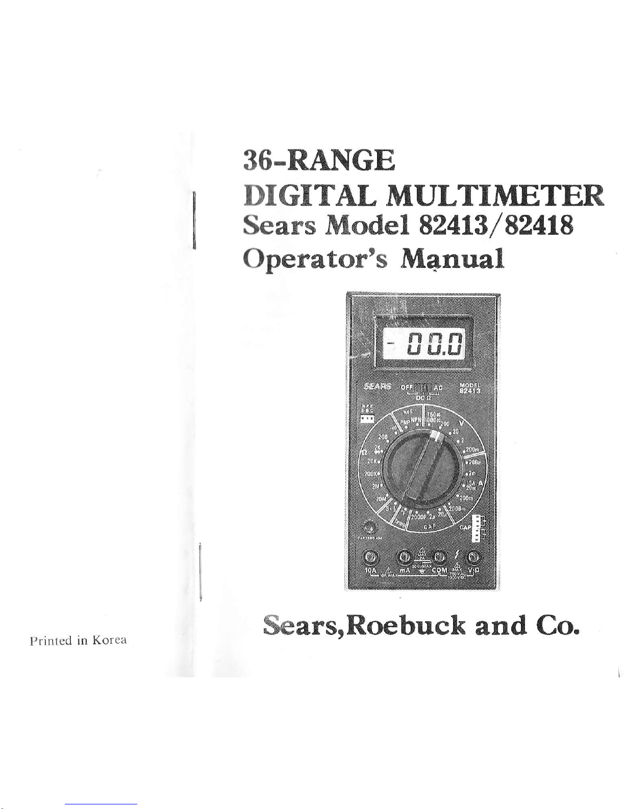
36.RA]\[GE
DIGITAL
MULTIMETER
Sears Model 82413
/
52418
Operator's M4nual
Printed
in Korea
SearsrRoebuck
and
Co.

I.
MULTIMETER
SAFETY
READ
this
information
before
using thc
tnctcr
WARNINGS
denote
hazards to
thc opcrntor'
CAUTIONS
denote
hazards
to the
mctcr.
SAFETY
RULES
1{arning
This tester
has been designed
with
yorrr
s.tlclt
itt trrind.
However,
no design can
completely
protcct .il',.rirrst
rrr(
(,r'tcct
use. Electrical
ci.rcuits can
be dangerous
rtrcl/r,r
l.tlr.rl
rvltcn
lack
of
caution or
poor
safety
practices arc
trst ti.
Read
the
Manual
Read this Instruction
Manual
carefully rntl
.,rrrplr'tt'ly.
Voltages and
currents within
the capabillty
ol trtt.isLtfc-
ment with
this test
equipment
can be
hazartlotts.
1,,11,,t'tlrc
instructions
in this manual
for every
meastlrclrlc
lrt
l{t .rtl rrttd
understand the
general
instructions
beforc
attclrrptirrll
tt,
use this tester.
Do not exceed the
limits
of
tllc tcstcr,
Safety Check
Double
check the
switch
before
making measutements.
instruc tions?
Disconnect the tester
or
changing
switch positions.
turn
off the
Do not
connect to circuits
with
voltage
switclr is in any
ohms or
current
position.
Whcn rcplacing
fuses use only
specificd
inscrt in correct fuse
notd"j.,,
_
setting,
and
lcad connections
Are
you
following
all of the
power before
present when
type
fuses
and
Don't
Touch
Don't
touch
exposed
wiring,
connections
or other
,,live,,
parts
of
an electrical
circuit,
If in
doubt,
check
the
circuit
first for
voltage
before
touching
it.
Turn
off the power
to
a circuit
before
connectins
resr
probes
to it. Be
sure
there is
no
voltage present
beforJ you
touch
the
circuit.
Do
not use
cracked
or broken
test leads,
High
Voltage
is
Dangerous
Always
start
with
the power
off,
Be sure
there
is no
voltage
present
before
nections
to
the
circuit.
making
con-
Don't
touch
the
tester,
its
test leads,
or any part
of
the
circuit
while it is
on.
Before
disconnecting
the
tester,
turn
the
circuit
offand
wait for
the
meter
to return
to
"zero.,,
Distribution
Circuits
Pack
a
Punch
In
high
energy
circuits
such
as distribution
transform.ers
and
bus bars,
dangerous
arcs
of explosive
nature
can
occur
if
the circuit
is shorted.
If
the
tester
is
connected
across
a
high
energy
circuit
when
set
to
a 1ow
resistance
range,
a
current
_range,
or
any other
low
impedance
range,
the
circuit
is
virtually
shorted.
Special
equipment
designed
for
use
with
these
circuits
is
available.
Conract
a
qualified
person
for
assistance
before
attempting
to
make
measurements
on
any high
energy
circuit.
SAFETY
rS
No ACCIpENT
-2-
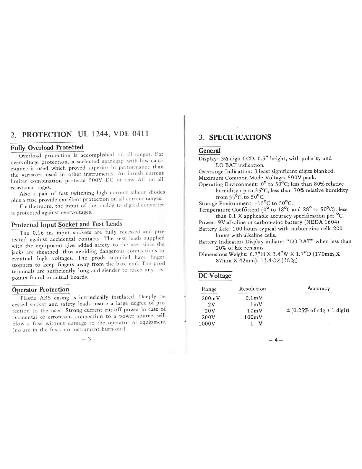
2.
PROTECTION-UL
1244,
VDE
O4I1
Fully
Overload
hotected
-
Ot*l..d
protection
is accomplishcd
orr rrll
t;trtllcs
For
overvoltage
protection'
a
seclected
sparkgap
witlr
low
capa-
cidance
is-used
which
proved
superior
in
pcrlirrtttrtrrcc'than
the varistors
used
in other
instrumcnts
Art ilrrrrslr
(
tlrrcnt
limiter
combination
protects
500V
DC
or lttrs
A(l
trrt all
resistance
rages.
Al.o
"
pair of
fast
switching
high
cttrrcrrt
siltc()rr
(li()des
plus
a
fuse
provide
excellent
protection
on
rll
'
ttttt
ttt
rrtrtgcs'
Furthermore,
the
input of
the
analog
to
ililiitrrl
I
()trvcrtcr
is
protccted
against
overvoltages.
Frotected
Inpuf Socket
and
Test
Lrads
The
0.16
in. input
sockets
are
fully
rcccsse'l
'ttrrl
pro-
tected
against
accidental
contacts
The
tcst
lcarls
srtpl>licd
with
the
equipment
give added
safety
to
tltc usct
sitrt.
the
jacks
are
sheathed
thus
avoiding
dangerous
corl'rfcti()rrs
to
-eventual
high voltages.
The
prods
supplicd
havc.
lirtgcr
stoppers
to k""p
fingers away
from
the
barc
cnd'
'Ilr(:
l)r'od
t"r-in"ls
are
sufficiently
long
and
slendcr
to
rcach
:tny tt:st
points found
in actual
boards.
Operator
Protection
pt"tri"
,ASS
casing
is
intrinsically
insulated'
Deeply
re-
cessed
socket
and
safety
leads insure
a
large
degrce
of
pro-
tcction
to
the
user.
Strong
current
cut-off
power
in case
clf
accidcntal
or
erroneous
connection
to a
power source,
will
blow
a
fusc without
damage
to
the
operator
or equipment
(rrt,
:rrc
in rlre
frts.
,
tlo itlstrultt.'nt
burn-out)'
3-
x
(0.25%
of rdg
+
1
digit)
3. SPECIFICATIONS
Geneil
oi"pt"y, ZUdigit
LcD. 0.5tt
height,
with polarity and
LO BAT
indication.
Overrange
Indication: 3
least significant digits
blanked.
Maximum Common
Mode
Voltage: 500V
peak.
Operating
Environment: 0o to
50oC;less
than
S}Vorelat\ve
humidity up to 35oC,
less than 70%
relative
humidity
from35oC.to 5OoC.
Storage
Environment:
-15oC
to
50oC.
Temperature Coefficient
(0o
to
L8oC
and
28o to
50oC):
less
than 0.1
X applicable accuracy
specification
per
oC.
Power:
9V
alkaline or
carbon-zinc battery
(NEDA
1604)
Battery Life:
100 hours typical with
carbon-zinc cells
200
hours with alkaline
cells.
Battery Indicator:
Display indiates
"LO
BAT" when
Iess than
2Mo
of life
remains.
Dimensions Weight:
6.7'.'Hx 3.4"'w
x
1.7t'D (17Omm
X
87mm
X 42mm),
13.4
O2
(3829)
DC
Voltage
Range
200mV
2V
20v
200v
1000v
Resolution
0.1mV
1mV
1OmV
10OmV
1V
Accuracy
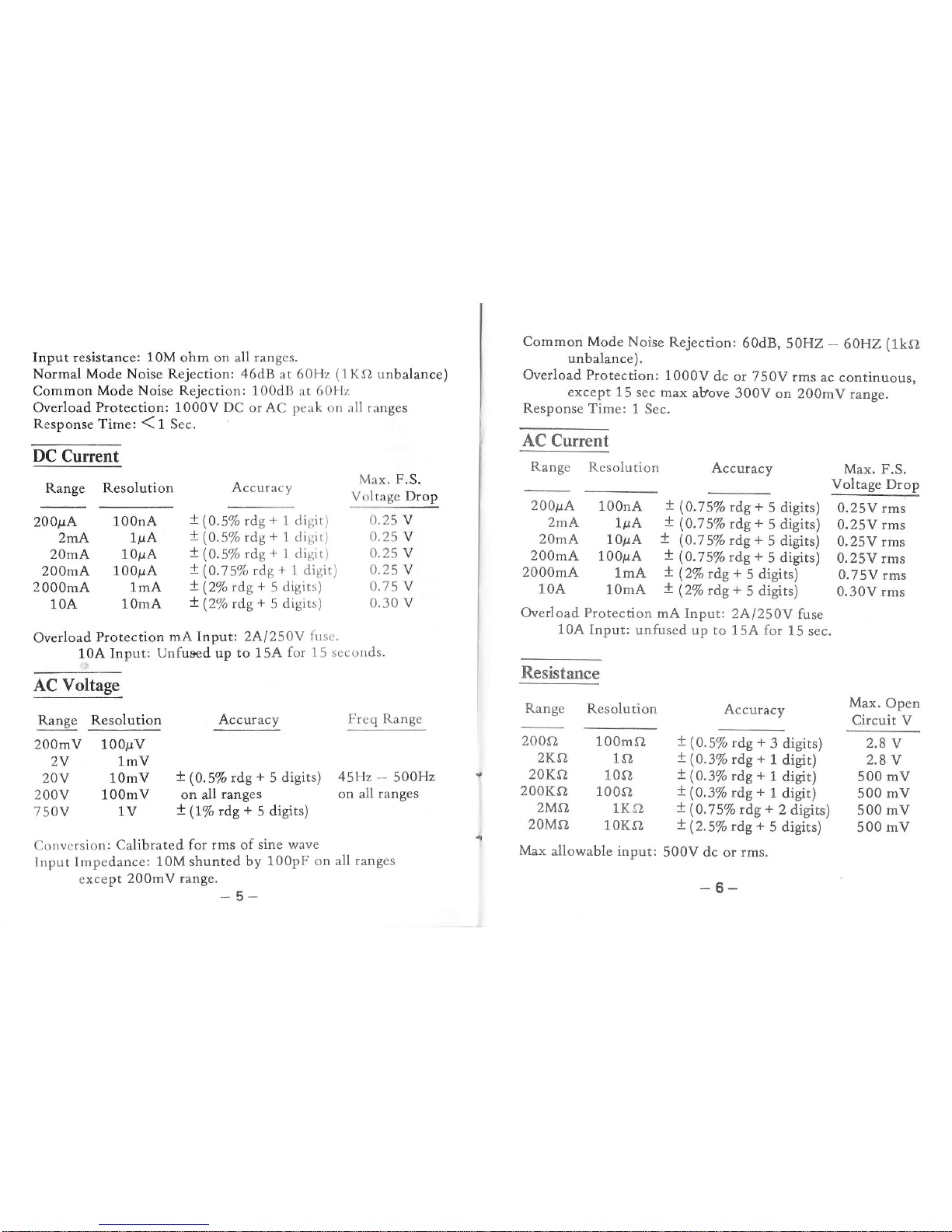
Input resistance:
10M
ohm on all
ranges.
Normal
Mode
Noise Rejection: 46dB at 60Hz
(1KO
unbalance)
Common
Mode Noise Rejection: 100dB
at
60llz
Overload
Protection: 1000V DC
or AC
peak on
rll
r:rnges
ResponseTime:(1Sec.
qqlsqeq
Range Resolution
Accuracy
Max. F.S.
Voltage Drop
Common
Mode
Noise
Rejection:
60d8,
5OHZ
-
60HZ
(1kS,
unbalance).
Overload Protection:
1000V
dc or
750V rms
ac continuous,
except 15
sec max
above
300V on
200mV
range,
Resoonse
Time:
1 Sec.
AC Current
Range
Resolution
Accuracy
200p4
zmA
20mA
200mA
200OmA
10A
Overload
Protection
mA Input:
2Al250Y
fuc.
10A
Input:
Unfused up to
15A
for 1
5
sccortds.
AC Voltage
Range Resolution
Acctrracy
200mV
100p.V
2V 1mV
20V 1OmV
!
(0.5% rdg
+
5 digits)
200V 100mV on all
ranges
750V lV
+
(l%
ds
+
5 disits)
200p"4
100nA
2mA
1pA
20mA
1OpA
200mA
10OpA
2000mA
lmA
10A
10mA
Overload Protection
mA Input: 24/250V
fuse
10A
Input:
unfused up to 15A for
15
sec.
Resistance
Range Resolution
Accuracy
100nA
!(O.5%
rdg
+
1 digit)
lp.A
!(0.5%
rdg
+
1
digir)
10pA
!(0.5%
rdg+
1 digit)
100pA
+(0.75%
rdg+
l disit)
1mA
+(2%rdg+5digits)
10mA
+(2%rdg+5digits)
0.25
V
0.25
V
0.25 V
0.25 V
0.75 V
0.30 v
x
(0.7
5%
rdg
+
5 digits)
!
(0.7
5% rdg
+
5 digits)
+
(0.75%
rdg
+
5 digits)
!
(0.75Vo
rdg
+
5
digits)
t
Q%
rae
+
5
digits)
+
(2%rdg+
5
digits)
Max. F.S.
Voltage Drop
0.25V rms
0.25V rms
0.25V
rms
0.25V
rms
0.75V rms
0.30V rms
Max,
Open
Circuit V
Freq Range
45Hz
-
500H2
on all
ranges
2004
100mO
2KA
ls}
20KO
10sl
200Ka
1000
2Ms}
1KO
20Mo
10KO
Max
aliowable input:
!
(0.5%
rdg
+
3 digits) 2.8 v
x(0.3%
rdg+
1
digit)
2,8v
x
(0.3%
rdg
+
1
digit) 500
mV
!
(0.3%
rdg
+
1
digit) 500 mV
X
(0.75Vo
rdg
+
2 digits)
500
mV
!
(2.5%
rdg
+
5 digits)
500
mV
500V dc
or
rms.
-6-
Convcrsion:
Calibrated for
rms
of
sine wave
lnput Impedance:
10M shunted
by 100pF
on all ranges
cxcept
200mV
trnt"._
U
_
 Loading...