

SETTING-UP INSTRUCTIONS MAINTENANCE MANUAL REPAIR INSTRUCTIONS AND PARTS LIST FOR

MOTOR CYCLE
MODEL NUMBERS 810 89571 AND 810 90572
This is the Model Number of your SEARS motor cycle. It will be found on a plate fastened do the steering head. Always mention this number when communicating with us regarding the motor cycle, or when ordering parts.
HOW TO ORDER REPAIR PARTS
All parts listed herein may be ordered through Sears, Roebuck and Co. or Simpsons-Sears Limited. When ordering parts by mail from the mail order house which serves the territory in which you live, selling prices will be furnished on request or parts will be shipped at prevailing prices and you will be billed accordingly
WHEN ORDERING REPAIR PARTS: ALWAYS GIVE THE FOLLOWING INFORMATION AS SHOWN IN THIS LIST.
2. The PART NAME
1. The PART NUMBER 3. The MODEL and SERIAL NUMBER 4. The NAME of item
This list is valuable. It will assure your being able to obtain proper parts service at all times. We suggest that you keep it with your other valuable papers.
SEARS, ROEBUCK AND CO. U.S.A. SIMPSONS-SEARS, LTD. CANADA
Sears 250 SGS - 66/16

SEARS MOTOR CYCLE

MODEL NUMBERS 810.89571 AND 810.89572
BATTERY SERVICE INSTRUCTION for Types 6 B 7 and 6 B 8
- 1. Fill the battery with electrolyte of battery grade to a liquid level of 10 mm (3/8") above the separators. The specific gravity should be 1,27 - 1,28 at 20° C (70°F) For tropical climates the specific gravity should be 1,22 - 1,23 at 30° (85° F) A tropical climate is considered one in which water never freezes.
- 2. Allow the battery to stand for at lease two (2) hours but no more than
- 2. Allow the battery to stand for at lease two (2) hours but no more than five (5).
- 3. Connect the battery for charging, plus to plus terminal and minus to minus terminal. The charging rate should be adjusted to 0,7 A approx. It is normal, when the charging current drops at the end of the charge. Observe specific gravity of electrolyte and voltage. When they remain constant, continue charging for three (3) hours. Final voltage per cell 2,6 2,7 volts. The total charging time will be 12 15 hours as experienced. If the temperature of the electrolyte exceeds 45°C (115°F), the charge must be interrupted, until the battery is cooled down.
- 4. Install the clean and dry battery, check the polarity, tighten securely the hold-downs, apply a thin film of mineral grease on the terminals. LIQUID LEVEL CONTROL. The liquid level should be maintained 10 mm (3/8") above the plates after the charge. If the level drops fill in only pure distilled water. If refilling is necessary in short intervals, the charging device should be checked.
If the battery is not in use for longer periods, it should be recharged monthly with half the current as mentioned above. High-Rate Chargers should be used only for a later recharging, but not
for the first installation. In this case also the temperature of the electrolyte should never exceed 45°C (115°F).
The battery is dry charged and may be used in emergency after standing of two (2) hours. But in this case there should follow a longer driving period of several hours or the battery should be recharged after short time.
Please observe these instructions and have your battery charged regularly. A long trouble-free life will be your reward.
SPECIAL OIL
Packed with your machine you will find one litre tin of special motor oil with oil additive and a further two plastic bottles of oil additive. Use the engine oil from the tin for the first filling of the oil tank (left tank opening). For the next two oil tank fillings mix the contents of one of the bottles with additive to the motor oil and stir thoroughly. Obey instructions regarding oil quality.
Models 810.89571 810.89572
Ref. TS 10/11-Ed. 5 Sears SGS
CORRECTION to Maintenance Manual No. 821809
Section 1 "SPECIFICATIONS"
NOTE: Ignition advance: 0.208 to 0.224 in. (5,3 to 5,7 mm) before T.D.C. on rear piston.
The torque figures for tightening bolts and screws are:
Figures with mark + are changed resp. newly added:
| Engine fixing bolts | 50 | - | Ft. | Lb.+ |
|---|---|---|---|---|
| Cylinder head screws | 21 | • | Ft. | Lb. |
| Primary drive sprocket | 108 | Ft. | Lb. | |
| Clutch hub tightening nut | 108 | Ft. | Lb. | |
| Gearbox sprocket | 108 | Ft. | Lb. | |
| Swing fork shaft nut | - 43 | - | Ft. | Lb. |
| Shock absorber joint bolt | - 43 | - | Γt. | Lb. |
| Axle for rear and front wheel | - 43 | - | Ft. | Lb. |
| Rear sprocket fixing screw | - 18 | - | Ft. | LЪ. |
| Fastening screws of oil pump Max. | 4,5 | - | Ft. | ĻЬ. |
| Crankcase screws resp | ||||
| Crankcase cover screws | - 6 | - | Ft. | Lb.+ |
| Brake cam fastening | - 7 | - | Ft. | Lb.+ |
Section 2 "SETTING-UP INSTRUCTIONS"
Final Work
- 2. Pull throttle twist grip on handlebar and afterwards put handlebar with rubber supplement levers pointing slightly downwards on top bridge of fork (watching the "securing pin against turning"), fit fixing clamp and tighten the four bolt screws.
- 2a. There are two new screws at the toolbox. Use new screws for mounting the handlebar (see point 2).
4a. Fix brake cable to hand lever on R.H. half of the handlebar.
- a. See under 4
- b. Push brake lever on hub backward
- c. See under 4
- d. Release brake lever on hub so the cable covering fits into the bracket of the adjusting screw.
- e. Loosen adjusting screw until the clearance to the lever is 3/4 in. Tighten the lock nut.
821822
- 7a. Attention: Fill in 1 1/2 pints of motor oil. When refilling do not open the level screw, as this shows minimum level and in any case oil will overflow on proper filling. When refilling after repair (engine completely dry) fill in 1.7 pints of motor oil.
- 9. Screw on tail light housing (connect green to green and grey to grey cable end).
- 10. Mount gear shift lever as individually wanted.
- 11. Mount rear brake lever and adjust individually so as to achieve correct braking effect.
12. See inspection chart (page 3-8) for predelivery inspection.
Additional hint to Section 3 part 4 "Inspection and Adjustment" page 3-9 "Adjusting the oil pump":
With new oil pump the normal oil consumption at average cruising speeds (about 40 m.p.h.) is 1 pint of oil to approx. 90-100 miles. With higher speeds and much riding on full throttle, oil consumption rises to 1 pint for about 75 miles. If oil consumption is within this range, don't change oil pump adjustment.
Section 6 "REPAIR INSTRUCTIONS", Page 20,
Ignition advance: 0.208 to 0.224 in. (5.3-5.7 mm).
Page 7-5, Ref. No. 1
For the two top piston rings on the piston, we ask you to use following spare part numbers: 253.2.10.260.1 Piston ring 45 mm dia.
| TRECON | T.TUB - | +5 mm ura | ||||
|---|---|---|---|---|---|---|
| 253,2.10.260.3 | Piston | ring, | overside | I, | 45,5 mm | dia. |
| 253.2.10.260.4 | Piston | ring, | oversize | II | , 46 mm c | lia. |
Page 7-5 Ref. No. 3
The pistons will be delivered complete with piston rings. We ask to order them with following spare part numbers:
| 253.2.10.206.0 | ` . | Piston | cmpl., n | normal 45 | mт | dia. | |
|---|---|---|---|---|---|---|---|
| 253.6.10.206.0 | Piston | compl., | oversize | I 4 | +5,5 mm o | lia. | |
| 253.7.10.206.0 | Piston | compl., | oversize | II. | 46 mm o | lia. |
Therefore following numbers are no more valuable:
253.1006.2, 253.1006.6 and 253.1006.7
Page 7-5 Ref. No. 6
Instead of 253.1015.0 read 270.1.10.015.0 Crankshaft compl.
Page 7-5 Ref. No. 18 Instead of 250.1100.0 read 270.1.11.000.0 0il Pump compl.
Page 7-15 Ref. No. 10 Instead of 250.1540.2 read 250.1.15.040.0 Air Filter compl.
821822
- Page 7-19 Ref. No. 12 and 12a Instead of 270.1.22.127.0 resp. 128.2227.0 read 270.1.227.0 Fuel cock compl.
- Page 7-19 Read under Ref. No. 20 24456 Fuel pipe sleeve (for fuel cock) 2 pieces 250.2219 Fuel pipe sleeve (for fuel tank) 2 pieces (new spare part to part 2)
under Ref. No. 22 only Instead of 900.0902/07 read 253.1.22.021.0 Fuel pipe complete (with two pieces 250.2219)
- Page 7-19 Raf. No. 33 Instead of 22887.1 read 900.1034 Hexagon head screw - M8 x 90 DIN 931
- Page 7-19 Ref. No. 41 Instead of 900.1001 read 901.1104 Hexagon head screw - M8 x 140 DIN 931-8G
- Page 7-23 Ref. No. 41 Instead of 128.2508 read 357.1.25.016.1 Rubber for foot rest
- Page 7-29 Ref. No. 51 Instead of 24773 Hexagon nut M6 DIN 934 read 900.2933 Hat nut M6 DIN 1587
- Page 7-31 Ref. No. 3a Instead of 901.4808 read 900.4846 Spring pin 6 x 16 DIN 1481
- Page 7-33 Ref. No. 61 Instead of 050.2.6203 read 25483 Ferule
- Page 7-35 Ref. No. 7 Instead of 175.4011.2 read 253.1.40.211.2 Brake operating lever
- Page 7-37 Ref. No. 41 Instead of 253.2810.0 read 128.2810.0 Rear chain
- Page 7-41 Ref. No. 46 Instead of 902.0743 read 250.5205.2 Cable plug
- Page 7-43 Without Ref. No. Instead of 253.2.70.010.0 read 253.3.70.010.0 Set of tools complete
SUPPLEMENT:
900.0133 Container with additive-oil 900.0134 Container with motor oil SAE 50 with additive-oil
Page 7-27 Between part 21 and 25a will be mounted 253.1.21.270.1 Guide bush (sleeve) 1 piece per shock absorber
Page 7-28 and 29 One washer will be mounted at the lower bore on the support for mudguard (Part 2): 250.3025 Disc 2 pieces
Sears 250 SGS - 66/16d

We are glad to learn that you have become owner of a
SEARS MOTORCYCLE
In more than half a century of producing bicycles and motorcycles our machines have been acknowledged international as products combining both broad experience and technology. To help this SEARS motorcycle to be your best friend, please read this rider's handbook carefully in order to become acquainted with the correct handling procedure and adjustments which are required from time to time.
If you have any questions about your motorcycle, please apply to your dealer who will be happy to assist you.
Contents
| Preface II | ||
|---|---|---|
| Section 1 | SPECIFICATIONS | 1 — 1 |
| Section 2 | SETTING UP INSTRUCTIONS | 2 — 1 |
| Section 3 | OPERATING AND MAINTENANCE | |
| Part 1 Operating Tips | 3 — 1 | |
| Part 2 Controls | 3 — 3 | |
| Part 3 Riding Tips | 3 — 4 | |
| Part 4 Inspection and Adjustment | 3 — 8 | |
| Section 4 | WIRING DIAGRAMM | 4 — 1 |
| Section 5 | TROUBLE SHOOTING | 5 — 1 |
| Section 6 | REPAIR INSTRUCTIONS | |
| Part 1 Special Tools | 6 — 1 | |
| Part 2 Engine | 6 — 3 | |
| Part 3 Chassis | 6 — 13 | |
| Part 4 Electrical Equipment | 6 — 17 | |
| Section 7 | SPARE PARTS LIST | 7 — 1 |
Section 1 SPECIFICATIONS
Engine
Number of cylinders: 1 split single-cylinder Bore: 2×1.77 in. (2×45 mm) Stroke: 3.07 in. (78 mm) Cubic capacity: 248 c.c. Compression ratio: 6.2:1 Peak performance: 16.5 HP at 5800 r.p.m. Maximum torque: 2.3 mkg at 3200 r.p.m. Ignition advance: 0.256 in. to 0.276 in. (6.5 mm to 7 mm) Spark plug: SEARS No. 60400 Spark gap of plug: 0.024 in. to 0.028 in. (0.6 to 0.7 mm) Lubrication: by oil-pump Cooling: air-cooled by wind in riding. Carburettor Puch-single throttle-slide carburettor Type P 32/1 1,28 in. (32 mm) diameter with needle jet Air filter: Wet air filter with starting disc
Main jet: No. 150 Position of needle: Clamp-spring clamped to 4th notch from top (see "Adjusting the carburettor") Idler jet: 40 Throttle-slide: width of slit: 0,748 in. (19 mm) Idler screw: about 1/2 turn open
Battery-Ignition-Lighting
Voltage regulating Puch D. C generator Performance of generator: 6 V 45/60 W Battery capacity: 6 V, 7 Ah Headlamp: 6,70 in. (170 mm) light outlet Main head light: 6 V 45/40 W.
Gearbox
Transmission from engine to gearbox: 51:22 i = 2,31
Transmission in gearing 1st gear: 22: 8 i = 2.75
2nd gear: 18:12 i = 1,5 3rd gear: 15:15 i = 1 4th gear: 13:17 i = 0.76
Transmission from gearbox to rear wheel 46:15; i = 3,07
Total Transmission:
| 1 st gear: i == 19,5 | 3 rd gear: i | = 7,1 | |
|---|---|---|---|
| 2 nd gear: i = 10,6 | 4 th gear: i | = 5,4 | |
| Clutch: Multiple-disc | clutch, friction | disks | run- |
ning in oil bath
Chain
Front chain of engine: Duplex-sheet roller chain 3,8 × 5,16 in. Diameter of sheet 0,196 in. (5 mm) Number of sheets: 64 Rear chain: Roller chain ½ × 5/16 in.; 118 rollers, 1 block, 2 connecting links
Wheels
Rim size: Drop center rim 1,85 × 16 in. (21/2 × 16 in. DIN 7816) Tire size: 3,00 × 16 in. front. 3,50 × 16 in. rear.
Tire pressure
Front wheel: 14,5 lb/squ. in. (1,0 atü) Rear wheel: 20 lb/squ. in. (1,4 atü) with pillion passenger 29 lb/squ. in. (2.0 atü)
Front and rear brake
Brake drum: diameter 7,08 in. (180 mm) Width of the brake lining: 1,575 in. (40 mm)
Fuel tank
Capacity 3,35 gals. (12,6 litres) of which 0,53 gals. (2 litres) are reserve fuel
Performance Data
Top speed: about 68,34 m.p.h. (110 km/h), 1 person riding upright;
Fuel consumption: about 0,70 gals. of petrol and about 1/s pint of oil for 62,13 miles (100 km) at approximately 43,5 m.p.h.
Hill climbing capacity: with pillion passenger about 40%
Action radius: about 210 miles (340 km) with one tank filling
Measurements
Lenght 78,10 in. (1970 mm) Height 36,22 in. (920 mm) Width 24,60 in. (620 mm) Wheel distance: 52,55 in. (1345 mm) Road clearance: 5,91 in. (140 mm) Saddle height: 28,9 in. (735 mm)
Weights
Weight without fuel, toolkit, and battery 300 lbs. (136 kg).
The torque figures for tightening bolts and screws are:
| Engine fixing bolts | • | • | 36 | ft. lb. | ||
|---|---|---|---|---|---|---|
| Cylinder head screws | • . • | 21 | ft. lb. | |||
| Primary drive sprocket | • | • | 108 | ft. Ib. | ||
| Clutch hub tightening nut . | • | • | 108 | ft. lb. | ||
| Gearbox sprocket 15 teeth . | • | • | 108 | ft. lb. | ||
| Swing fork shaft nut | • | 43 | ft. lb. | |||
| Shock absorber joint bolt . | 43 | ft. lb. | ||||
| Axle for rear and front whee | 1 | 43 | ft. lb. | |||
| Rear sprocket fixing screw | 18 | ft. lb. |
Section 2 SETTING-UP INSTRUCTIONS
Instructions for unpacking, assembling and carrving out final operations.
Carefully follow the procedure explained hereafter for getting your motorcycle ready to start!
Opening the Crate
- 1. Tear the carton open on the side and pull out the wooden box with motorcycle in it.
- 2. With a hammer hit the upper cross beams of the wooden frame from underneath until they can be removed.
- 3. Also remove the side wooden brace so that the motorcycle stands unconfined on a wooden floor in front of you.
Primary Preparing Works
- 1. Remove the nylon cover by cutting it open. Then mount the handlebar (see point 1 "Final Work") in order to avoid damaging the bowden cable.
- 2. Loosen screws on both fixing clamps with 19 mm wrench but be sure to lossen the lower nuts at first to prevent a damage of the foot rest axle thread. Don't loose the screws. Now the machine can be taken off from the wooden floor.
- 3. When the motorcycle is taken off from the wooden floor prop up the motorcycle.
- 4. Open tool kit on the left hand side of the shell frame and prepare wrench 11 mm.
Final Work
- 1. Loosen the four bolt screws with 11 mm wrench of handlebar fixing clamp and detach the connecting link.
- 2. Put handlebar with rubber supplement, levers and bowden cables pointing slightly downwards in symmetrical position between handlebar fixing clamps and tighten the four bolt screws. Choose handlebar position after riding experience as individually wanted!
-
3. Mounting of the electrical switch.
- The electrical switch, during transport fixed to the fork, is to be mounted on the handlebar lefthand side. The fixing clamp is connected with the switch by two bolt screws which are to be tightened with a screw driver.
-
4. Fix clutsch cable to hand lever on l. h. half of the handlebar.
- a) First of all completely screw in hand lever adjusting screw "1" and appropriate lock nut "2" and turn until the slits of adjusting screw, lock nut and hand lever bracket "3" aline (so that the bowden cable may be inserted).
- b) Remove r. h. crankcase cover and push external clutch lever on the crankcase forward.
- c) At the same time put nipple "5" of the cable into hole on the bottom of the hand lever "4" and put cable into slits.
- d) Release clutch lever on the crankcase so the cable covering fits into the bracket of the adjusting screw.
- e) Loosen adjusting screw until the clearence of the lever is 5 mm. Tighten lock nut.
5. Attachment of the foot rests.
Fit foot rests "R" as indicated in drawing. Tighten fixing screw bolt "13" with 19 mm wrench on both foot rests.
Choose position of foot rests as individually wanted, but don't fit them too low as you would then be unable to change gear without taking the left foot from its rest!
6. Batterv.
Note! The battery is charged, but delivered without any electrolyte. Make the battery ready for service. See section 6, part 4.
- 7. Fill oil in gearbox.
- 8. The ignition key is in the tool box.
Help the "SEARS" motorcycle to work for you efficiently. We trust it will afford you great satisfaction.

Section 3 OPERATING AND MAINTENANCE
Part 1
OPERATING TIPS
- Both daily and periodic inspections should be made as this prolongs life of the motorcycle and help to prevent accidents.
- Proper-attention to tightness of important parts should be given as this also helps to prevent accidents.
- Warm-up the engine at low speed for about two minutes. Lubrication oil does not circulate well and carburettor does not function well when the engine is cold.
- Do not race the engine unnecessarily. The engine runs at an excessive speed with full throttle at no load. This is harmful to the engine.
- Start the motorcycle gently and shift gears according to the speed. High rev. number on low load is harmful to the engine.
- Change gears gently by pressing or pulling the gear change lever lightly with your toe. Do not change gears roughly. Rough gear changing results in rapid wear of the shift guide plate, etc.
- Do not operate the motorcycle with the air cleaner removed. Dirt and dust will be inhaled into the engine and cause rapid wear.
- Remove the switch key and lock the steering head when parking. This prevents the motorcycle from being stolen and the battery from being discharged.
"Break-in" Instructions
The way of riding the vehicle and its treatment during the "Break-in" period are very important for the duration of life and economical fuel consumption.
With two-stroke engines, the power is greatly dependent on the tightness of pistons as the latter control the movement of the gas. Correct runningin of new cycles is, therefore, of vital importance. Also, with new cycles, the first 1250 miles should be covered with an additional petrol-oil mixture in the proportion of 1 part oil to 50 parts fuel or 5 cubic inches of oil to 1 gallon of fuel. The fuel should be thoroughly mixed with the oil in some clean vessel, before filling. Of course, the oil tank, too, must be filled with oil as the ordinary pump lubrication has to work at the same time. Proper running-in is achieved by very gradually increasing the strain on the engine to its peak performance after having ridden the model over a distance of about 200 miles on little gas. These initial 200 miles must be done without carrying a pillion passenger and without tackling any stiff gradient. Don't ride faster in top gear than about 40 m. p. h. Don't
either stick to riding at an even speed all the time. Change your riding speed every now and then, vary your speed. Change into lower gear when speed drops below the rate indicated for that particular gear. When riding in town-traffic, no special care in this respect need be taken.
From 200 to 600 miles a steady, moderate cruising speed should be maintained, with interposed short sprints up to half-open throttle. Increase your average speed gradually up to from 43 to 53 m.p.h. in top gear. When going uphill, ride on little gas. changing down rather than straining your engine. Give your engine a chance to cool down. From 600 to 1300 miles you may continue to keep up a fast cruising speed with interposed short speedbursts up to full throttle, avoiding at the same time riding for any length of time at maximum speed attainable. Even after having done above 1300 miles, don't all at once try to ride all out, but when speeding throttle down from time to time. At the beginning, this should be done every mile or so. With progressing running-in, these intervals may gradually become less frequent. But even when your model has finally completed its running-
OPERATING TIPS
in period, it will be expedient — when driving at speed — to throttle down just for a short time. It is advisable to run in your model without stopping over some distances longer than 70 miles. We point out once more that too low revolutions are also unfavourable. Change speed in time, that is, from top to 3rd at about 27 m.p.h., from 3rd to 2nd at about 20 m.p.h. and from 2nd to 1st at about 12 m.p.h.
Important!
During the period of "Break-In" don't fail to repeatedly examine all screws, bolts and nuts, in particular those holding the engine (as also those of the rear engine suspension) nor fail to perform controls, tests and lubricating just as prescribed (Service-Station). You are also earnestly advised to drain the oil from the gearbox after about 500 miles, and to rinse it with rinsing-oil and then to fill it up with fresh oil.
Fuel
The Cycle is not run on a petrol-oil mixture. The fuel and lubricating oil are kept separate, the fuel being filled into the right half of the tank and the oil into the left half.
Insure that dirt or dust not become mixed with the fuel.
Insure that water does not become mixed with the fuel.
Lubricatina oil
For engine lubrication (in the oil tank): Always use a good grade oil. Use only nondetergent oil. At temperatures over 50° F (10° C) SAE 50.
At temperatures over 50° F (10° C) 5AM 50. At temperatures from +15° F (-10° C) to 50° F (+10° C) SAE 40
At temperatures below +15° F (-10° C) SAE 30. For gearbox and telescope forks: Use heavy oil in summer, in winter a thin winter oil. Thicker oils may cause the clutch to stick or lead to stiffness in the front fork.
Part 2

Footopered gearshift lever

Lighting switch

Lighting switch and ignition switch. a) Dimmerlight b) Highbeam 2 Hoon butten
Chocke and Tickler

Filler caps
When opening turn 1/3 rotations to the left.
Steering-lock
Before locking, turn handle gear to the right insert key into the cylinder of barrel locks, after this turn key to the left, and push it together with cylinder of barres lock inwards, turn key to the right and pull it off. The opening ensues in reversed order.
PIDING TIPS
Sundry hints
Before starting a new engine, be sure that the telescope fork has been filled up with a sufficient supply of oil. For this purpose unscrew drain plug screws (slotted screws) placed at the fork of the first (fig. 1/1) and the nuts placed ad the top bridge piece (fig. 8/5). For checking the quantity of the oil contained, it will be advisable to drain off all of the oil and then re-fill again. Normal quantity of filling 5 cu in. (80 ccm) each leg. Damping, and subsequently, the softness of the springing depends on the viscosity of the oil. After having covered about 3000 miles (5000 km) drain off the oil and

fill up with fresh oil. Test oil level in enginegearbox while the cycle stands perfectly vertical: To ascertain whether there is sufficient oil, oil must escape from the opening after the oil level screw (fig. 2/1) has been unscrewed.
Entire quantity of oil contained about 1,6 pints.~ Test tire pressure (front 14,5 lbs/squ. in. = 1 at), rear wheel 20 lb/squ, in (1.4 at): with pillion nas. 29 lbs/squ. in. (2.0 at).
The battery, too, has to be filled up and charged from an outside source (battery charger! - See chapter on electric equipment).

Fig. 2
Starting the engine
Put the ignition key into the lock. Having done that, blue charging light and green control lamp of idling gear light up. If there is no green light, the idling gear is to be charged by means of gear lever (green light lights up). Open petrol tap (fig. 2/3). Three positions (fig. 3).

Close the starter disc on the air filter (fig. 2/4). The carburettor is provided with a special starter carburettor. The twist grip is turned to full throttle position, then the tickler (fig. 2/5) on the float housing is repeatedly depressed at short intervals, until petrol flows over the opening of the chamber containing starting petrol (fig. 9/1). In summer it is unnecessary to close the starter disc. It suffices to depress the tickler a few times, and there is no need for the fuel to overflow
Open the twist grip 1/4 at most before kick-starting. Depress the kickstarter smartly,
Let the engine warm up a little at a moderate number of revolutions, particularly in winter. If there is a tendency to refuse to fire or to stall, briefly depress the tickler button and open the starter disc, after the engine has got warm.
A hot engine will start without using the tickler or closing the starter disc with 1/4 gas at most. Should the engine have cooled down already and fail to start, the tickler can be operated briefly again. Use of the tickler with a hot engine involves the danger of getting too fat a mixture. If the carburettor has been flooded with the engine hot, the mixture is much too fat and the engine will not start. In such a case start with full throttle repeatedly, until the engine is running.
Important! Before kickstarting: don't start the engine with the ignition switched off.
Stopping the engine
Stop the engine by taking out the ignition. Always switch off the ignition. Then turn off the petrol tap. Otherwise, if the cycle is standing on an incline or resting sideways, the carburettor may overflow, which will lead to starting difficulties (flooding the engine). In this case the overflown petrol should be drained off by the same screw (fig. 11/1) situated in the bottom of the crankcase.
The stand is put down with the left foot. Then, with your right foot, step smartly on the stand shoe, at the same time drawing the maschine upwards and backwards upon both legs.
Riding and gear changing
Operating of gear lever: Push foot gear lever (fig. 2/2) down for lower (slower) gears, draw upwards for higher (faster) gears. Always declutch well before changing gear! Gear shifts work easily, don't force your change speed lever.
Putting gears into neutral: Press the gear lever down until you feel it to be free: the 1st gear is then in. Then with the point of your toe, slowly draw upwards, until engagement in neutral is felt. Neutral should not be engaged between 2nd and 3rd or 3rd and top gears. Before changing down, do not turn off gas intirely. After starting, change into 2nd at about 10--12 m.p.h., into 3rd at about 30 m.p.h. The flexibility of the engine is such that it can bi run slowly even in top and the accelera-
tion is good when the throttle is opened. Below 25 m.p.h., however it is not advisable to run all the time in top and the third gear may be used permanently without hesitation for lower cruising speeds. For instance in town-traffic, acceleration of up to 45 m.p.h. are permissable in 3rd gear. although this speed should not be maintained in 3rd for any length of time. The gear ratios have been selected for sporting rides. Thus to obtain high average speed in hilly country, the difference of ratio between top and 3rd gear is not too great. On mountain roads when the speed has dropped to some 40 mph change down to 3rd. This applies above all to sporting riders. The excellent pull of the engine allows of outstanding hill climbing performance even at low engine revs. but the speed will be lower than when a timely changedown has been effected.
Brakes
Braking effect and braking reliability are particularly good with excles with rear wheel springing as the wheels do not give in braking. Make it your rule always to use both brakes. Try it and you will get used to it! You need not hesitate or be nervous to apply the front wheel brake! Its effect is even greater than that of the rear brake on account of the rising load on the wheel. Only when the road is slippery or icy you will have to be careful. Always brake your mount when approaching a bend. Braking on a bend increases the likelihood of a dangerous skid. Vilolent and sudden braking on slipperv bends, particularly with the front wheel brake, is dangerous. You get less braking effect with the wheels locked and the risk of skidding is greater. The brakes are therefore to be "felt" rather then forced. The brakes are soft and very efficient, which greatly facilitates good braking.
Removal of wheels
Front wheel: Slacken the clamp screw of the righthand fork lug (fig. 4/1). Unhook the brake cable (fig. 1/2). Unscrew stub axle (fig. 4/2). While refit-
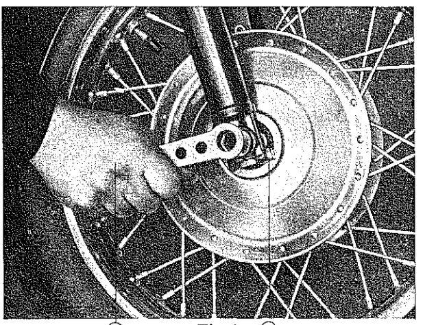
Fig. 4 🤇
ting, insert the bolt of the brake plate in the hook of the spring fork (fig. 1/3) and then screw up the stub axle. Drive fork down on the springs several

times before tightening the clamp screw on the right-hand fork lug. Rear wheel: Unhook brake rigging, after having loosened winged nut (fig. 5/1). Unscrew stub axle by means of spark plug wrench. Pull out the intermediate part left-hand (fig. 5/2) — representing brake-stop — and pull the carrier of brake-drum from the flexible coupling. Incline the machine and remove the wheel from under the mud-guard. The hinged part of the rear wheel mud-guard can be taken off by unscrewing it. This makes it possible to remove the rear wheel without inclining the model as in a side car model. Grease stub axle when reassembling.
Tire fitting (fig. 6)
To take out a tire first unscrew dust cap of valve, depress valve needle until the air is entirely released, unscrew nut on rim and push out the valve. The drop center rims used derive their name from the groove in their center. The cable-edges of the straight-sided tires can best be removed from the rim by placing a foot upon the rim on the side opposite to the valve, thus having the weight of one's body press the steel cable edges of the tire

Fig. 6
down into the dropped center or groove of the rim. This action will produce enough space on the valve side of the cover to enable you to insert a tire lever and slip the cable-edge of the tire over
the edge of the rim. Now the edge of the tire which has been slipped over the edge of the rim has to be held in place with the lever, while by means of a second lever the remaining circumference of the tire has to, be pulled over the rim edge by slipping the second lever, which has also been inserted between tire edge and the edge of the rim, along the entire remaining circumference of the tire. This done, the inner tube can be removed. When refitting, the inner tube, having been slightly inflated and well powdered with talcum, is inserted into the cover. While doing so, one has to be very careful

Fig. 7
not to pinch or squeeze the inner tube or twist it unduly and has to see to it that the protective ribbon, which is to protect the tube from the nipples of the spokes, evenly covers the bottom of the groove of the rim. When inserting the wheels, proceed in reversed order of operations as described above. Particular care has to be taken to get the correct chain tension and wheel alignment (see chapter on chain tensioning) as well as to fix and assemble the various removable parts most accurately.
Steering damper
On bad roads and at speed, it is advisable to tighten the steering damper (fig. 8/1) to a moderate degree. Since every driver wants the damping to suit his own requirements, the most suitable

Fig. 8
tension is found out by trial. The outstanding roadholding qualities of Model 250 allows of riding under all conditions with the damper left slack. Thus there is no need to tighten it up too much. It must, however, neither be left too loose!
Riding hints
Fuel consumption and wear of the cycle are largely dependent on how the motorcycle is being used. High speeds necessarily mean high consumption. Much variation of speed. constantly turning the twist grin sharp braking on bends increase wear and consumption with any vehicle. The most favourable consumption figures are obtained with a uniform speed. The fuel and oil consumption of our models are extremely low, and the rider should not unnecessarily increase it by bad riding. Letting in the clutch with a jerk, powerful braking, wrenching at the twist grip at lower engine speeds, brisk gear changing, possibly without proper declutching or regard to engine revs. inconsiderate riding on the worst roads; all these are additional stresses which can only add to the wear. A good rider never jerks his cycle and his gear change proclaims itself only by the gradually changing revolutions of the engine.
IMPORTANT HINTS
The engine knocks
Knocking (pinking) is a metallic ringing sound in the engine, sometimes irregular but mostly synchronized with the firing stroke. The cause of this too rapid (detonating) combustion of the mixture is a fuel too poor in anti-knock quality. The anti-knock value of fuels is dependent on their octane number — the higher the latter, the greater the freedom from knocking.
Standard brand fuels at the present time are approximately octane 72. With these, the 250 c.c. engine runs without knocking, except perhaps briefly when opening out the throttle. Fuels not sufficiently knock-free are bad for the engine and should not be used. If a knocking fuel must be used in case of no other being available, ride carefully and not above average speeds. Permanent knocking must be prevented. Such preventatives are: Advance ignition not to exceed about 0,256 in. (6,5 mm). Rich mixture: If the engine should knock up to half throttle screw up screw for air regulating; lift jet needle, above half throttle fit
larger main jet. Reduce compression ratio by fitting two cylinder head gaskets.
All these preventatives against knocking tend to diminish performance and to raise consumption. However, this trouble inherent to unsuitable fuels, must be accepted when using them.
Adjusting the carburettor
For this work see section 6 part 2.
Spark plua
There is no such thing as a standard plug which will suit all types of engines equally well. Manufacturers of plugs therefore produce a diversity of types to meet the working conditions of various types of engines.
Use SEARS-plugs only (No. 60400)! in case you have none with you, only such plugs should be used as are signified by their makers as suitable for air-cooled sports engines. Plugs for water cooled engines are unsuitable.
We would particularly stress the fact unsuitable plugs, with too low resistance to overheating, and those which start to glow, may damage the engine. Plugs for sport engines are sometimes known as "cold" plugs, since they do not become too hot even with hot engines.
In case of doubt, it is better to employ a plug which is too "cold", which may perhaps oil up sometimes when running slowly but cannot damage the engine in any way.
It is advisable to screw up the plugs by hand as tightly as possible, before using a wrench to avoid damage to the thread.
Plugs made to be dismantled must not be put into a vice, but taken to pieces with a box spanner only.
Muffler (Silencer)
With two-stroke engines, the silencer is not an unavoidable nuisance, but an important element in the control of the gas flow through the engine. The engine and silencer of our cycles are designed to cooperate most efficiently with one another and to the best advantage.
Any alteration in the silencer spoils the tuning and unfavourably effects performance and consumption.
The inside of the silencer should be cleaned from time to time as obstructions have an unfavourable influence.
INSPECTION AND ADJUSTMENT
Daily Inspection
Inspect the motorcycle yourself. Prober inspection prolongs the life of the motorcycle.
- 1. Does steering handle operate lightly?
- 2. Is front brake lever play 3/4"?
- 3. Is rear brake pedal travel 8/4"?
- 4. Does clutch work properly?
- 5. Do front and rear cushions work properly?
6. Do head light, tail light, and stop light turn on?
- 7. Does horn sound properly?
- 8. Is engine oil up to full mark on gauge?
9. Does fuel tank contain sufficient gasoline?
- 10. Does oil tank contain sufficient oil?
- 11. Is front tire pressure correct?
- 12. Is rear tire pressure correct?
- 13. Is colour of exhaust gas proper?
|
EDELIVERY
PECTION 2) |
BI |
REAK-
AFTEF |
IN
{ |
А |
ALW
FTER |
AYS
EVER |
Y |
|
|---|---|---|---|---|---|---|---|---|
| PRI | AS | 500 | 1500 | 3000 | 3000 | 500 | 1500 | 3000 | 6000 | ITEMS | |
| | | 0 | • | ۲ | 1 Clean (decarbonize) cylinder and exhaust assembly | ||||
| ۲ | ۵ | • | 2 Clean spark plug | |||||
| • | • | ۲ | 0 | 0 | ۲ | 3 Clean and oil air filter 3) | ||
| ٠ | ۲ | • | 4 Clean fuel strainer and connecting screws for oil pipe | |||||
| • | • | ۲ | ۵ | 5 Clean carburetor and adjust the engine idling | ||||
| • | ۲ | ۲ | 0 | ۲ | ۲ | 6 Adjust clutch | ||
| • | ٩ | ۲ | ۲ | • | 7 Adjust ignition timing | |||
| 8 Fill oil tank and bleed 4) the oil pipe | ||||||||
| 0 | 0 | • | 0 | 0 | ۲ | 9 Chek oil pump setting | ||
| 0 | 10 Chek brake linings | |||||||
| • | • | • | 11 Adjust front brake | |||||
| • | • | - | ۲ | ۲ | 12 Adjust rear brake | |||
| - | - | - | -[ | - | 0 | 13 Check chain and engine sprocket | ||
| 1 | • | ۲ | 0 | · 0 | 6 | • | 14 Adjust and lubricate drive chain | |
| - | ٥ | 15 Lubricate hobs | ||||||
| - | - | ۲ | 16 Lubricate steering bearing | |||||
| - | - | 17 Fill up telescopic fork oil | ||||||
| - | 0 | 18 Change telescopic fork oil | ||||||
| - | - | - | - | 0 | 19 Change shock absorber oil | |||
| 20 Inspect tightness of bolts and nuts | ||||||||
| • | 6 | 0 | 0 | 6 | 0 | 21 Inspect tightness of cylinder head screws | ||
| • | • | 0 | - | - | 0 | 0 | 22 Lubricate chassis | |
| • | • | 0 | 0 | • | • | 23 Lubricate control cables | ||
| _ | 6 | 24 Check motor oil in gearbox | ||||||
| _ | -1 | ••• | • | 25 Change motor oil in gearbox 5) | ||||
| • | -| | - |
| |
26 Fill and load battery | ||||
| -[ | • | 27 Check battery acid | ||||||
| • | • | • | • | 0 | 0 | ٥ |
28 Inspect lighting system, charging control and carbon
brushes |
|
| 0 | • | • | 29 Inspect horn sound | |||||
| 0 | 0 | 0 | • | 30 Check tyre pressure | ||||
| • | - | - | 0 | 31 Clean and lubricate drive chain | ||||
2) At mail orders the predelivery inspection is not executed — take care that this inspection is done. 3) Every 500 miles on extremely dusty conditions. 4) Every time when oil tanks is empty; THEREFORE BE CAREFUL TANK WILL NOT BE EMPTY. 5) At least twice a year.
Maintenance
Proper attention to the mount together with proper handling and regular servicing assures constant reliability.
Attention covers the lubrication of the whole machine checking, adjusting and cleaning. Those who value the appearance of their cycle, however, will not neglect the outside either.
Lubrication
Engine lubrication is provided by on oil pump driven by the engine, the regulating member of which is coupled with the throttle twist grip, its action depending on the engine revolutions and load.
Use suitable lubrication oil (see chapter on lubricating oil). While running in your cycle also use petroil-oil mixture (see "Running-in").
Adjusting the oil pump
To check the setting, the small flange on the engine casing (fig. 9/1) is taken off. The fixed red mark on the casing (fig. 9/2) and the marks of the movable white scale (fig. 9/3) will then be seen. The oilpump is properly adjusted when, with the twist grip at full throttle, these marks coincide. This standard setting is also used during running-in.
Only after running-in has been completed, should the setting be altered if necessary. With average cruising speeds (about 40 m.p.h.) the normal oil consumption is 1 pint of oil to approx. 175 miles. With higher speeds and much riding on full throttle, oil consumption rises to 1 pint for about 150 miles. Even with very good lubricating oil, the oil pump should not be set for appreciably less than the quantities mentioned. To change the fresh oil feed, the twist grip is turned to full throttle position and after loosening the lock nut the setting screw of the bowden wire of the oil pump (fig. 9/4) is adjusted. When the screw is unfastened

Fig. 9
the movable white scale mores and the + (plus) mark on it shifts towards the fixed setting mark in the casing while the oil feed is increased.
Conversely, screwing up the setting screw decreases the oil feed and the — (minus) mark on the scale moves towards the fixed setting mark.
Do not set consumption to anything above 1 pint of oil to 175 miles at average speed (that is 1400 miles per 1 gal, oil).
Lubrication of gearbox
This is provided by pouring oil into the gearbox through the opening, after removing plug screws. The normal content is about 700 c.c. (about one and a half pint). On the left hand crankcase cover there

Fig. 10
is an oil level indicator screw (fig. 2/1). Oil is filled into the gearbox until, after removing the oil level screw, oil begins to overflow from the opening. In summer use heavy engine oil; in winter with temperatures below freezing point, use thin winter oil. Heavy oils in winter may cause the clutch to stick and make gear changing hard. Change the oil after the first 500 miles. After about 4000 miles, check the oil level by unscrewing the oil level screw. If no oil issues, refill until it does. Change the oil after obout 6000 miles. With the engine hot, the drain screw on the clutch housing (fig. 10/2) and the one under the gearbox with oblique seat (fig. 10/3) are unscrewed until all the oil has been drained. Flushing out the gears with thin flushing oil is recommended. About one pint of flushing oil is poured in, the engine started up, top gear engaged and the machine allowed to run on the stand for a short time. The flushing oil is then drained off and the gearbox filled up with fresh oil as prescribed. By this charge of fresh oil the gear chain of the engine, the clutch, the starter and the gear change mechanism are lubricated simultaneously.
Telescope front fork
Each leg of the fork is filled with about 1/6 pint of oil. After 4000 miles, this oil is drained off (drain screw below on the fork lug, fig. 1/1). Fill up with fresh oil (1/6 pint each fork) after removing upper plug screw. The same oil is used as for the gearbox, in summer heavy engine oil, in winter thin winter oil.
If oil leaks from the fork, have the packing rings put right as soon as possible (renew them if defective).
Swing fork rear wheel springing
Lubricate axle of swing fork by means of a grease gun after every 1800 miles (1 nipple fig. 5/3). The sliding inner parts of the spring unit are greased by the damper oil.
Oil change of spring unit:
Change oil after the first 3000 miles and whenever damping decreases. If both bottom securing worm screws (fig. 5/4), the top joint bolts and the bottom joint bolts (fig. 5/5) have been removed, the spring unit can be taken off. Dismantle damper cylinder containing the oil and have oil changed. Mind that the quantity of damper oil is correct, that is to say 47/8 cu. in. (80 c.c.). A decrease in damping can easily be ascertained by giving the rear mud guard a hearty push down, while watching whether the swing forks come to rest at once (well damped) or whether they continue swinging up and down several times (badly damped).
Dismantling the damping cylinder (see Repair Instructions)
Other parts to be lubricated:
Nipples to be lubricated with the gun are arranged as follows: One nipple on the outer casing for the bowden wire of the clutch left-hand side at the bottom of the crankcase (fig. 2/6). One nipple on the shaft of the foot brake pedal (fig. 5/6). One nipple on the intermediate lever of the brake rigging (fig. 5/7). Have these nipples supplied by four or five shots of the gun; every 1500 miles one nipple each on the brake shaft bearing of the front and rear wheels (fig. 1/4 and 5/8): every 1500 miles. 1 or 2 shots of the grease gun, not more, to avoid grease getting on the brake shoes. Moreover, a few drops of engine oil to be applied every 1500 miles to the bearings of the controls on the handle bar, the joint of the starter lever (fig. 10/4), the joints of the stand, the joint of the foot brake rod, the lower connection of the hand brake bowden wire on the brake lever of the front brake as well as on the open cable (fig. 1/5) and the spring eyes of the saddle which become accessible when the latter is pressed down into the hollow of the tank. Every time a wheel is taken off, the stub axles should be greased (grease gun lubricant). Every time after charging the battery, clean and grease terminals.
Chains
As a matter of principle, chains should never be allowed to run dry and must always be correctly tensioned. For chain tensioning see chapter "Adjustments". Before starting to ride always have a look through the control gap at the chain and lubricate it with oil if necessary. Any not too thin oil is suitable for this purpose. If nothing else is available, oil can be taken from the tank of the machine. Dry chains become stiff and get tensioned by themselves and then rapid wear is unavoidable. Every 1500 miles remove the chain and wash it thoroughly in petrol. followed by a bath of hot liquid chain grease Excess grease is wiped off after cooling. In refitting the chain, the spring clip of the connecting link should always be placed with the closed end in front and towards the direction in which the chain moves (fig. 7).
Contact-breaker of the dynamo
After 1500 miles, the cover of the dynamo must be removed and the lubricating pad of the contactbreaker greased with heat-resistant grease. At the same time, check the contact-breaker (see chapter "Electrical Equipment").
Twist grip
Turn back the outer end of the rubber sleeve, unscrew the slotted head screw under the bore of the twist grip tube, pull off end cap and grip. Grease interior parts thoroughly.
Care of tires
Maintenance of the tire pressure as prescribed (see chapter "Specification") is most essential to assuring long life of the tires. If a tire pressure gauge is not available, it is better to run on tires pumped hard than on too little pressure. With slack tires, the wear is greatly increased. The springing of the cycle guarantees comfortable riding even with hard tires. Hard braking increases wear.
Damage to the tread should be repaired by vulcanising because if water is allowed to penetrate through any slits in the outer covers it is bound to ruin the tires.
Checking, Adjusting, Cleaning
Every 500 miles
Check battery acid, top up with distilled water, if plates are not fully immersed (see chapter "Electrical Equipment").
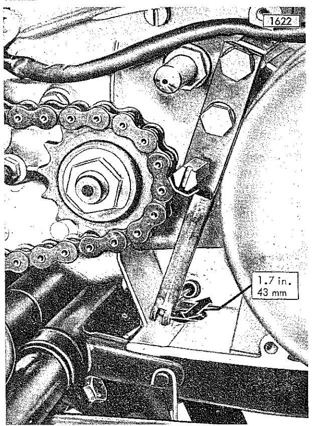
Chain Tension
Checking with the machine loaded by the rider! The section of the chain must show the usual sag of about ,394 in. (10 mm), that is to say, you must be able to move the chain vertically up and down for about ,784 in. (20 mm). Adjust chain tension after partly unscrewing the left and right nuts of clamp sleeve (fig. 5/9) by giving equal turns to both ten-
OPERATING AND MAINTENANCE
sioning screws (fig. 5/10). If the wheel is screwed up when in a slantwise position, that is, when alignment is incorrect, this will cause rapid wear of the chain and sprockets. Having tensioned your chain and tested whether or not the chain is too tight in one place, the sag mentioned above must be in evidence even in the tightest part of the chain.
Clutch
Fig. 11
The clutch hand lever must, as usual, have a little play. If no play at all is observed, or if the play, measured at the end of the hand lever, exceeds about ,472 in. (12 mm), adjustment is required. This is done by turning the setting screw (fig. 11/3 and 11/1) behind the dynamo in the middle of the cover plate. Tightening this screw decreases the play of the clutch hand lever. If the clutch cable is much stretched it may be found that this screw cannot be screwed up any more. In such a case the set screw (fig. 11/1) is loosened by some 3 turns and the clutch cable adjusted by means of the setscrew (fig. 2/7) placed on the left in front of the engine block. While doing this, the hexagon head of the screw must be held and only the nut need be turned. Fine adjustment is now performed by means of the set-screw (fig. 11/1).
Brake adjustment
The hand and foot brake levers must also have a slight play. The front wheel brake is set by means
of the wing nut (fig. 1/7) situated on the left hand fork. Unscrewing this nut causes a decrease of the play. First slacken the lock nut (fig. 1/8); the foot brake is set by the wing nut on the foot-brake lever (fig. 5/1). Turning it clockwise (seen from the front) reduces the play.
Every 1500 miles
Clean the air filter (on dusty and sandy roads every 500 miles). Remove filter after partly unscrewing the retaining screw, rinse by immersion in petrol, then condition the filter cloth by dipping in engine oil and allow excess oil to drain off. Clean spark plug electrodes with a wire brush. If necessary, bend over the side electrode so that the gap is ,024 in. to, ,028 in. using a spark gap gauge. Check up the contact breaker in the generator when greasing the lubricating pad (see "Electrical Equipment").
Every 3000 miles
Check the ignition setting and also the generator (see chapter "Electrical Equipment"). Clean the carburettor (see chapter "Carburettor").
Check steering play
If there is any play, with the front wheel of the raised cycle — especially in a direction transverse to the pivoting axle — when the steering main bearing is tested, the latter will have to be adjusted. To do so, proceed as follows. Loosen clamp screw (fig. 8/2) and slacken carefully upper lock nut (fig. 8/3), tension the lower setting nut (fig. 8/4) — it has normal righthand thread — until play has disappeared almost entirely. It is dangerous to screw up the main bearing too tight and for this reason, leave slight play. Screw up clamp screw. Hold the lower setting nut and tighten the upper.
Adjusting the twist grip
The smaller of the two slotted screws on the inner end is provided for setting the resistance of the twist grip. Set the resistance, so that the twist grip does not move back of itself.
Adjusting the headlamp
This adjustment can best be made at night on a straight level road. Slacken the two fixing screws in the headlamp bracket and, while seated with a pillion rider on the machine, that is, with the normal load on the cycle, adjust the headlamp in such manner that the beam strikes the road about 262 ft. ahead. Then tighten up the fixing screws again.
Cleaning
When washing down the machine with a hose, the jet of water should be kept away from the following parts: Generator, carburettor, space between brake drum and carrier plate, space between wheel hub and cover plate, steering head bearing, speedometer. If petrol or paraffin is used for cleaning, see
that it does not get into the brakes as the brake linings may become defective.
Electrical Equipment
For this work see section 6, part 4.
O V E R H A U L I N G
General
The work described can be carried out by any rider who is technically minded. Small manipulations which would be obvious to the latter are not therefore described in detail. Those not versed in such work had better leave it to an expert. Thoroughness and cleanliness should be the principles observed in overhauling.
Decarbonising the engine
Residues from combustion (oil-carbon) mainly accumulate in the exhaust ports, restricting the opening and reducing the performance. After about 4000 miles, the exhaust pipe is removed and a pocket torch used to see how far the exhaust ports are coked. If the clear opening is still approximately rectangular in shape, carbonisation is still unimportant, but if the form of the opening is irregular it should be decarbonised. Reduced engine performance is likewise a symptom of coked-up exhaust ports. When decarbonising proceed as follows: Unscrew bolts holding down cylinder head (fig. 12/1)

Fig. 12
with care (use box spanner) and take down gasket. Unscrew union of exhaust pipes and turn pipes (12/2) away (from engine) so that they allow of free access to the engine. Take off carburettor (12/3). When removing the cylinder the tank has to be lifted. The front part of the tank is lifted and kept in this position by the handle of a hammer, which is placed on the edge of the steering damper. For this purpose remove the front fixing bolt first and then rear fixing bolt. The oil hose is disconnected from the tank by removing the oil nipple. The oil is either drained off or prevented from leaking by inserting a suitable screw at once (fig. 12/4). As the fuel connecting hose allows of this movement it need not be taken off.
Lift off the cylinder. Clean exhaust ports (by means of a scraper or screw driver). Scrape carbon deposit from the top of piston or piston head and clean interior of cylinder head. Test piston rings. When reassembling, take care not to damage the cylinder head gasket and fit it properly. The fixing bolts of the cylinder head should be screwed up crosswise. Removal of the cylinder becomes easier, if the tank is entirely removed. Then the fuel has to be drained off. Before refitting the tank, the cable distributor fixed to the top tube of the frame should be oiled.
Cleaning the mufflers
For the purpose of cleaning it is not necessary to remove the muffler complete, it will do to take out the inner member of the silencer. First loosen nut of fixing screw for interior parts (fig. 5/11) and pull out screw. After having removed slotted screw, take out inner member (5/12). The separation of the two halves of the interior parts is done by unscrewing the two connecting screws. Now all the spaces in which the expansion of the gas takes place are accessible and can easily be cleaned. Change asbestos twine if ruined. Clean steel wool in petrol. Assembling in reversed order.
We urgently warn against changing the mufflers or removing some of the interior parts, as this operation would cause a drop in performance of the engine as well as an increase of fuel consumption. On no account will you obtain an increase of performance, as is sometimes erroneously believed.
Cleaning the carburettor (fig. 20 of "Repair Instructions")
Loosen clamp (fig. 9/5) of the carburettor and take off the latter. Unscrew fixing nut (6) of the float chamber and take off the latter. Unscrew the needle jet (7) together with the main jet (4). Unscrew the cover of the float chamber (8) and take out of the float (9). Wash all parts in petrol. Blow through the bore of the main jet (4).
Cleaning the idling jet.
Unscrew idling jet (10). Blow through the bore. Refrain from forcibly tightening the idling jet as this may damage it, but screw up well. Before re-
fitting, close the throttle twist grip so that the jet needle is visible in the lower part of the carburettor. Push the needle jet (7) with main jet on to the jet needle (11) and then only start to put parts in place and to tighten threads. Before putting on the float housing cover, insert the float needle (12) in the guide of the cover (8). Finally, the petrol pipe, the tap and its filter are to be cleaned. The tap must be unscrewed for this purpose.
Electrical equipment
Everything we need to know regarding servicing
of the electrical equipment is quoted under the appropriate heading (see "Repair Instructions").
Overhauling the brakes
When the wheels have been removed, the brake plates together with the brake shoes can be taken out of the brake drum.
Never use petrol or paraffin on the brake linings!
If the rivets of the brake linings are worn down the lining should be renewed. This work should be done by an expert motor mechanic.
Section 4 WIRING DIAGRAM

- 1 Head lamp, bulb 6 V, 45/40 W
- 2 Combined switch, control lamps bulb 6 V, 0,6 W tubular bulb 6 V, 3W
- 3 Dimmer switch
- 4 Horn
- 5 Highbeam headlight indicator
6 Generator
- 7 Ignition coils
- 8 Spark plugs
- 9 Stop light switch
- 10 Battery 6 V, 7 Ah
- 11 Rear- and stop light bulb 6 V, 5/18 W
Section 5 TROUBLE SHOOTING
As long as operating and maintenance instructions are closely observed, there is no reason for troubles to be expected. If however troubles occur, it is of supreme importance to locate an overcome the trouble immediately in order to prevent more costly damages.
more cosily damages. Inadequate handling in case of defect must be avoided at any rate. Consult in time a reliable workshop. For all requests for information and orders of spare parts it is indispensable to quote the characteristic number of the vehicle. Here after are given some hints for the loscalization and renair of some defects
| Trouble | Cause | Remedy |
|---|---|---|
| Engine does not start |
Operating error (fuel
cock closed) defective ignition i. e. spark too weak, misfires |
First remedy error, operate starting
aid, open fuel cock, refuel. Check plug for spark. Detach igni- tion wire from plug, hold it at about 0.5 cm distance from zentral electro- de and crank the engine. Spark good: Inspect fuel feed and carburettor (see below). Spark insufficient: Check spark upon cylinder cover. Hold ignition wire at about 0.5 cm distance from earth (e. g. cylinder cover), crank the engine. Spark good: Inspect sparkplug gap, reset. Spark insufficient: Inspect breaker point gap, contact break points, abble constitution |
| Fuel supply interrupted. |
By operating the tickler, check car-
burettor for fuel. No fuel in carbu- rettor: Repair float needle and/or fuel supply. |
|
| Engine does not start | Short-circuiting button jammed resp. ignition key no contact. | Set right. |
|
Vehicle bent or fallen
over with open fuel cock. |
Start with throttle wide open. If
necessary, open drain plug (crank- case bottom) and drain the necessary amount of fuel. |
|
|
Trickler or starting aid
operated with warm en- gine, engine drowned. |
Remedy as above. | |
|
Engine produces a few
sparks before stopping |
Fuel supply partly or
entirely interrupted. |
If there is no operating error (see
above), check float chamber for fuel or jets for dirt or water. Inspect fuel supply to carburettor by pulling the fuel line from carburettor. In this way check lines, filters etc. for cloggings by proceding in the direc- tion towards the fuel tank. |
|
Engine starts, but
kicks back |
Ignition too much
advanced. |
Reset ignition timing. |
| difficultly from could |
Electrical equipment:
Spark-plug gap too wide. Thermal value of spark-plug to high. Carburettor: Jets clogged, starting aid not operated. |
For nominal value and remedy see
Specifications. |
| difficultly in very frosty weather | The colder it is, the harder the engine starts. |
Use winter grade oil of high quality
(in gearbox), which facilitates cran- king. |
|
Items to be observed for starting.
Operate the starting aid, operate the tickler, open the throttle by 1 /s. If engine starts, let it warm up at low speed; do not open throttle completely before operating tempe- rature has been reached. Push back starting aid as soon as possible. |
||
|
Engine starts, but difficult-
ly from warm |
Mixture too rich
because of exaggerated use of starting aid or tickler. |
Open throttle completely during starting process. |
|
Engine runs, but
misfires, fires back, stops |
Lack of fuel in car-
burettor or tank, fuel cock closed, fuel feed |
Remedy the respective cause. |
TROUBLE SHOOTING
| Trouble | Cause | Remedy |
|---|---|---|
| stops when throttle is being opened |
Main jet clogged, water
before main jet. |
Remedy as above. |
| irregulary with misfiring |
Ignition misfires due to
incorrect working of contact breaker elec- trodes shortcircuited by foreign body or oil car- bon, spark-plug gap too wide e. g. owing to ex- cessive wear of plug electrodes, spark-plug carbonized or oily or under lead tarnish (tracking current along insulator), insulator cracked e. g. owing to incandescent ignition (sparkover in the plug), ignition lead loose, broken, ignition lead with accidental ground. |
For repair see respective section. |
|
Engine runs, butoutput
insufficient |
Engine misfires induc-
tion and compression bad, mixture too rich or too lean, ignition point improper, exhaust blocked, engine carbo- nized, crankcase oil seal rings leaky, breather screw loose. |
For repair see respective sections. |
| runs hot after a while |
Improper ignition
timing, insufficient lub- rication, exhaust blocked, engine carbo- nized, cooling air insuf- ficient due to dirt on cooling ribs. |
Adjust ignition, clean the engine. |
|
consumes too much
carburettor reports (backfires) |
Starting aid working all
the time, fuel consump- tion due to leakage in pipes, carburettor floo- ding (float valve leaky). When engine hot: Plug too hot, preignition due to combustion products upon plug or in combus- |
For repair see respective sections. |
| knoeks, pinks |
Improper fuel (insuffi-
cient knockresistance), too much spark advance. Mechanical causes: Bigend bearing, crank- shaft bearing, gudgeon pin worn out, too much piston play. |
For repair see respective. |
| hisses |
Insulator or plug bro-
ken, plug insufficiently tightened, plug sealing or faying surface of cylinder cover defective, breather screw not tightened. |
Remedy the respective cause or con-
sult workshop. |
|
Engine stops by itself:
Gradually after misfiring |
Insufficient fuel fee due
to gas bubbles, water or dirt in carburettor, plug carbonized, oily. |
Remedy as above. |
| suddenly |
Fuel tank empty, fuel
feed interrupted, jets clogged. Misfires owing to interruption or short circuit. |
Remedy as above. |
|
Engine does not stop when
switched off, but goes on running regularly |
Plug is not switched off
because shortcirculating button (resp. ignition switch) defective. |
Shut off fuel cock, repair button (switch). |
| Carburettor fire |
Backfiring in the car-
burettor owing to too lean mixture, handling with open fire. |
- If fuel cock accessible shut fuel
supply and open throttle fully so as to empty the carburettor. Use spe- cial extinguisher, choke flames by |
Section 6 REPAIR INSTRUCTIONS
Part 1
SPECIAL TOOLS

Loosing (a) and tightening (b) of driving sprocket
Pulling off the driving sprocket
Pressing out the roller bearing

Mounting the crankshaft

Measuring of axial play
Adjusting the ignition timing

Adjusting the regulator

Adjusting steering play

Loosening of union nut

Spoking in

Oil filling — into telescopic fork

Engine assembly stand
Part 2
ENGINE
DISMANTLING OUT OF FRAME
- 1. Loosen battery clamp screw. This disconnects battery from ground.
- 2. Loosen clamp screw of foot brake lever and take off brake lever.
- 3. Remove crankcase cover on the right-hand side after unscrewing the three retaining screws.
- 4. Turn rear wheel until chain master link appears. Remove master link, lift chain from gearbox sprocket, replace master link.
- 5. Screw adjusting screw of clutch lever (fig. 2/1) at engine block so far out that the clutch lever can be taken out of its guide, unhitch cable from slit in clutch lever. (Do not lose slit nipple!)
- 6. Remove cover for generator, disconnect generator cable from connection plate and pull it out of generator housing.
- 7. Unscrew nuts of upper rear engine mounting screw, lift fairing plate fromscrew ing cover of carburettor housing, remove throttle piston and cover from Bowden cable.
- 8. Loosen mounting screw of flexible speedometer drive and remove it together with clamp of generator cables (fig. 1/5), pull out flexible speedometer drive.
- Loosen shackle of carburettor and pull off carburettor, pull out throttle piston after unscrewend, unscrew slotted screw on the opposite side of the frame, remove fairing plate.
- 10. Pull plug cable from spark plug.
- 11. Undo the three cable straps holding Bowden cables and oil hose together, unscrew connecting screw of oil hose from engine block and pull it out, put open hose end quickly into filling hole of oil tank (fig. 1/1).
- 12. Unscrew nuts at exhaust pipe flanges (box wrench!), loosen clamp at tube supporting foot rests and remove exhaust pipes.
- 13. Unscrew nut of forward mounting screw of fuel tank and pull out screw (be careful not to lose spacers), unscrew lock nut and nut of rear fuel tank attachment and knock out screw lightly, until holding washers release the tongues of the tank, so that the tank can be raised (fig. 1/2). Fix tank in raised position by pushing under it a hammer or wooden wedge that rests on the

Fig. 1: Chassis after removal of engine
- 1 Oil hose put into filling hole
- 2 Fuel tank raised
- 3 Connecting hose
- 5 Clamp of generator cables
- 6 Clamp of guide tube of clutch cable
hand wheel of the steering damper. The connecting hose (fig. 1/3) permitts this movement, so there is no need of draining off the fuel. However, the engine is more easily accessible if the fuel tank is removed completely. For this purpose, drain off fuel and remove connecting hose (fig. 1/3).
- 14. Detach Bowden cable for oil pump from lever on upper frame support (fig. 1/4).
- 15. Unscrew lock nut of engine mounting screw (top, front), remove clamp of guide tube for clutch cable (fig. 1/6), pull guide tube out of crankcase.
- 16. Unscrew nuts of the engine mounting screws, pull out screws, remove both tongues of forward engine support.
- 17. Raise front part of engine block slightly so that rear attachment becomes free, lift engine out

Fig. 2: Engine block. right side view
- 1 Adjusting screw of
- 4 Gearbox sprocket 5 Stav bolt
- lutch lever 2 Armature of generator
- 3 Armature extractor
- 6 Nut of speedometer gear spindle bolt
- 7 Stud of crankcase
of frame. If the fuel tank has been removed. lift it out to the left: if the tank has only been raised, raise engine block a bit and remove it to the right (on account of the fuel cock).
DISMANTLING ENGINE (using the Engine Repair Stand No. 250 7017).
Cylinder head:
- 1 Unscrew spark plugs.
- 2. Unscrew cylinder head screws by means of box wrench (spec.tool No. 250.7015) (proceeding crosswise from outside to inside) and lift off cylinder head, taking care not to damage the gasket.
Cylinder and pistons
- 1. Unscrew nuts of cylinder base flange and lift off cylinder, taking care not to damage the pistons now falling forward against the crankcase with the connecting rod.
- 2. Mark the pistons, remove snapring from face of wrist pin by means of round-nose pliers, push out wrist pin, but be careful not to interchange them, and take off piston.
On no account should the skirt of the piston be cleaned by removing the oil carbon, even if it is quite black. The piston rings must move freely in their grooves. Do not remove piston rings without good reasons! Rings that are stuck and their grooves should be thoroughly cleaned of carbon. When removing the piston rings, do not damage or unduly stretch them. Do not interchange them and put them back into their correct position. Rings blackened along the greater
part of their circumference indicate their failure to provide a gas-tight fit and should be replaced by new rings.
Crankcase cover. left-hand side
- 1 IInscrew clamp screw of foot-operated gearchange lever and pull off gearchange lever
- 2. Unscrew camping holt of kickstarter lever, take off lever (do not lose thrust bolt with spring) and pull the hub of the kickstarter lever off its
- 3. Unscrew retaining screws of the left-hand crankcase cover and remove cover Do not damage the mating surfaces! Do not lose thrust washer of kickstarter shaft! When removing crankcase cover, the oil will
drain out, so place a fan underneath engine!
Clutch, gegrbox sprocket and generator
1. Unscrew the five collar nuts retaining the clutch springs, using a screw-driver with recess. For this purpose the spring retainers must be lifted from their retaining grooves by means of another screw-driver (see fig. 3). Remove clutch thrust plate and clutch discs. Take out compression nins and hall

Fig. 3: Unscrewing the collar nuts
- 2. Insert clutch hub holder (spec. tool No. 253.7014 consisting of some old clutch discs welded together) and chain sprocket clamp (Part No.253.7031). On the right side of engine block first unscrew stay bolt (fig. 2/5), then flatten lock disc of the retaining nut of the gearbox sprocket (fig. 2/4). Unscrew nut and remove sprocket with extractor tool (Part No. 250.7013). Remove cotter pin (Woodruff kev).
- 3. Remove carbon brusher of generator, unscrew mounting screws and remove base plate. Remove the armature (fig. 2/3) by means of the extractor screw (Part No. 22733) (fig. 2/3).
- 4. Clutch hub holder and chain sprocket clamp remain in position. Now flatten lock discs of the
clutch hub retaining nuts and of the engine sprocket. Unscrew nuts of the clutch hub with the socket wrench (fig. 4) and pull clutch hub from the shaft.

Fig. 4: Dismantling the clutch: Unscrewing the hub locking screw
Unscrew retaining nut of the engine sprocket and remove the sprocket with the extractor tool (Part No. as above) (fig. 5).

Fig. 5: Extracting the engine sprocket
Now engine sprocket, primary chain and clutch drum can be removed simultaneously. Remove bushing and thrust collar clutch drum as well as woodruff-key and spring washer from the crankshaft stub.
Starter
- 1. Remove dog clutch gear of kickstarter together with spring.
- 2. Remove snapring from intermediate gear and remove intermediate gear.
Oil pump
Remove safety wire, unscrew mounting bolts and take off pump.
Crankcase
- 1. Knock out both crankcase locating pins (fig. 2/7) with the aid of a drift pin.
- 2. Unscrew catch guide with catch and spring from the right-hand half of the crankcase.
- 3. Unfasten connecting screws and remove righthand half of crankcase. As the crankshaft runs in a roller bearing in the right-hand half of the crankcase, this half can be removed without the aid of a tool. Under no circumstances should the two halves of the crankcase be separated forcibly by means of a screw-driver or a similar tool. (Be careful of the 0,1 mm [0,00394 in.] spacers underneath the races of crankshaft roller bearing and mainshaft roller bearing!)
Gearbox and Crankshaft
- 1. Pull out mainshaft (fig. 12/1) and remove mainshaft gears. Take thrust collar and roller bearing out of race in the left-hand half of the crankcase.
- 2. Remove gearshift rail with gearshift yokes.
- 3. Remove countershaft (fig. 10/1) with gears and thrust collar for the right-hand roller bearing. Take roller bearing out of race in the right-hand half of the crankcase.
- 4. After dismantling the gearbox the crankshaft can be pressed out. (Do not knock it out!)
Gearchange
This part should not be dismantled except in case of breakage, of any part failing to function properly, or for the purpose of getting the faces of the housing smoothed for a better gas-tight fit.
- 1. Unscrew the countersunk screw (fig. 9/7), now shim plates and spring housing (fig. 9/3) and shift guide plate with curved gates (fig. 9/8) can be removed.
- 2. Dismantle snapring from interior gear shift lever and remove the latter with rachet wheel (fig. 8). Push out guide sleeve.
- 3. Unfasten countersunk screw (fig. 9/1) and nut (fig. 7/4) and remove supporting plate (fig. 7/1).
Speedometer drive
- 1. Unscrew nut (fig. 2/6) from speedometer gearspindle bolt which carries the driving helical gear and press out spindle bolt.
- 2. Remove securing pin from driven helical gear by means of a punch, then remove helical gear downwards and pull out shaft upwards. The bearing bush should not be pressed out. If this is really considered necessary, the securing pin must be bored out.
Wash all engine parts in kerosene or other solvent. The mating surfaces of crankcase and cover are cleaned with the aid of a scraper.
To examine the gearbox there is no need to dismonthe the left-hand grankcase cover and the clutch The oil need not be drained either.
While the engine is still hanging in the frame and the driving chain has not vet been removed the gearbox sprocket (brake rear wheel!) and the armature of the generator (engage gear and brake rear wheel!) are pulled off. The removed engine is laid on the left-hand case cover (all the oil runs into the clutch space), then the crankcase pins are knocked out and the crankcase connecting screws are unfastened. After removal of the right-hand half of the crankcase the gearbox is freely accessihle
For removing the kickstarter gears or the oil nump. as also for exchanging the front (engine-to-clutch) chain, the engine can be left in the frame. After dismantling the left-hand foot rest, the clutch lever and the kickstarter lever, the left-hand crankcase cover is removed. (Place a vessel underneath it to collect the oil flowing out.) Now the clutch is dismantled and removed together with the engine sprocket. Then the front chain can be exchanged, or the kickstarter gears or the oil nump can be removed. The oil pump should not be dismantled except for good reasons.
Pressing out of Bearings
When pressing out defective bearings, proceed as follows
To avoid damaging the bearing seat through the processes of pressing them out and in, it is advisable to warm the crankcase to about 140° F. (about 60° C.), so that it feels hot to your hand.
(Use of Electric Hot Plate: when using an open flame place a flat metal plate between the flame and the crankcase.)
a) Left-hand crankcase
- 1 Knock out worm drive of oil pump and exterior small ball bearing by means of a mandrol
- 2. Press out seal ring and large interior ball bearing in the direction towards the crankcase with a mandrel whose diameter is slightly smaller than that of seal ring.
b) Right-hand crankcase
For pressing out the roller bearing employ special tool No. 250.7011.2 (fig. 6). The right-hand seal ring is pressed out only if defective.
Seal rinas
With two-stroke engines a proper gas-tight seal of the crankcase is indispensable to efficient engine performance. The seals used are rings made of oilproof rubber. The part adjoining the shaft must have a sharp edge. The tension of the spiral spring must be such as to make the ring fit snugly and tigthly along its entire circumference. The shaft itself must be perfectly smooth, without play, and must not knock. For exchanging the seal rings as
well as the bearings a press with suitable stamps and base-parts has to be used. When fitting these rings care must be taken not to tear their edges.

Fig 6. Pressing out the roller bearing
ENGINE REASSEMBLING
Bearinas
Test bearing for easy running lack of axial play and firm seating on shaft and in the housing. Bad fit on the shaft can be overcome by fitting a new bearing. If the seats in the crankcase have been damaged, a new crankcase will have to be installed. a) Left-hand crankcase
-
- 1. Press in large interior ball bearing from inside
- 2. Press in seal ring from outside, its sealing edge facing outward. The worm drive of the oil nump and the small exterior ball bearing are not assembled until the two halves of the crankcase have been screwed together
b) Right-hand crankcase
- 1. Press in right-hand seal ring from inside with its sealing edge facing inward.
- 2. Press in first ball-bearing and then roller bearing from inside.
- c) Crankshaft
Before pressing the crankshaft with its long journal into the left-hand half of the crankcase, heat crankcase together with bearing as described, then oil the ball bearing. After the crankshaft has been pressed in, its axial play (0.00787 in.) has to be checked by means of a crankshaft distance gauge in the following way: Place the distance gauge (Part No. 253.1032.5 L 1) on the level surface of the left-hand crankcase and test if the
measuring face marked (+) (35.5) touches the shoulder oft the crankweb without play. If there is still some play eliminate it by inserting 0.00394 in thick spacers. Should it prove necessarv to use four or more spacers, the crankshaft had better be removed agin an half the snagers inserted at the long shaft journal so that the crankshaft remains well centered The measuring should be caried out without the gasket.

Fig 6a. Distance gauge for crankshaft
Now press the race of the roller bearing on the shaft journal. If gear shift and gearbox are assembled, the right-hand half of the crankcase can be put in place and screwed down. Only when that has been done, the worm drive of the oil pump with the aperture facing inward, and finally the small ball bearing, can be pressed into the left-hand crankcase from outside.
Test crankshaft for easy running. If the turning is somewhat hard, give both journal ends some light taps with a rubber or light-metal hammer in an axial direction, whereupon it will run easily.
Speedometer drive
- 1 Insert drive shaft from above and push the driven helical gear into it from below. Insert and fasten securing pin.
- 2. Press in spindle bolt of speedometer gear and lock it by means of the nut. Pay attention to easy running of gears and shaft.
Gearchanae
- 1. Assemble supporting plate (fig. 7/1) together with hairpin spring (fig. 7/2), put on securing disc (fig. 7/3) and screw on put (fig. 7/4). Screw in countersunk screw (fig. 9/1) from outside and secure the latter by a blow with a blunt chisel, then tighten nut (fig. 7/4).
- 2. Insert guide sleeve in the bushing of the supporting plate (fig. 7/5), the slotted end pointing towards the interior of the gearbox, fit interior gear shift lever (fig. 9/2) and secure it from the outside by means of the snapring. Insert rachet wheel in the position indicated in fig. 8 (fig. 9).
3. Install spring housing (fig. 9/3), spacer shim (fig. 9/4), disc (fig. 9/5) intermidiate disc (fig. 9/6)

Fig. 7: Assembling the supporting plate
- Supporting plate
- Hairnin spring 3 Locking disc
- ting plate to receive the guide sleeve

5 Bushing of the suppor-

Fig. 8: Rachet wheel of automatic gear shift

- 1 Countersunk screw 5 Disc
- 2 Interior gear shift lever
Spring housing
4 Spacer shim
-
6 Intermidiate disc Countersunk screw
- 8 Gear shift guide plate
and countersunk screw (fig. 9/7). With the aid of the gear indicator bring slot of the guide sleeve into alignment with the slot of the rachet wheel. Fit gear shift guide plate (fig. 9/8), tighten countersunk screw and secure it with a punch mark.
Gearbox
1. Install countershaft (fig. 10/1) with gears, fit thrust collar (fig. 10/2) and roller bearing (fig. 10/3) with rubber seal (fig. 10/4) for clutch thrust pin. The open side of the roller bearing cage must face the interior of the gearbox.

Fig. 10: Gearbox
- 1 Countershaft
- 2 Thrust collar
- 3 Roller bearing of
- countershaft
- 4 Rubber seal
- 5 Left-hand gear shift voke
- yoke 7 Second-speed spur gear 8 Third-speed spur gear
6 Right-hand gear shift
- 9 Gear shift rail 10 Roller bearing of main-
- r shift 10 Roller bea shaft
Fig. 11: Gearbox
1 First-speed spur gear 2 Second-speed spur gear 3 Third-speed spur gear
- 2. Install left-hand gear shift yoke (fig. 10/5) and right-hand gear shift yoke (fig. 10/6) in such a way that the left-hand yoke engages with the guide spline of the second-speed spur gear (fig. 10/7) and the right-hand yoke engages with the guide spline of the third-speed spur gear (fig. 10/8). Put in gear shift rail (fig. 10/9) and fit it into the guide hole in the crankcase.
- 3. Install roller bearing (fig. 10/10) of the mainshaft into the left-hand half of the crankcase (the open side of the cage facing the interior of the gearbox), fit in thrust collar and first-speed spur gear (fig. 11/1) with pawl slots facing the inner side of the gearbox. Then insert spur gear of the second speed (fig. 11/2) and that of the third speed (fig. 11/3) in such a manner that left-hand and right-hand gear shift yokes engage with the guiding splines of the gears and each pair of gears engages with each other.
- 4. Insert mainshaft (fig. 12/1). If 0,1 mm (0,00394 in.) spacers were inserted under the race of the roller bearing, these have to be fitted again and then the race is put on.

Fig. 12: Gearbox
2 Race of the roller bearing
Crankshaft
1 Mainshaft
See the chapter "Fitting a new crankshaft".
Crankcase
- 1. Apply gasket-making compound to the mating surfaces of the left-hand half of the crankcase, put a new paper gasket on them and soak the gasket on its upper side with oil.
- 2. Replace right-hand half of crankcase (use rubber mallet), taking care not to damage the ring seals (use spec. tool 250.1000.0 W 18). Knock in crankcase pins (fig. 2/7), screw in and tighten up connecting screw.
6 — 9
Oil pump
(Follow the instruction for assembly most carefully!) (fig. 13)
- 1. Turn plunger B to its highest position.
- 2. Coat the packing surface of the pump and the corresponding surface of the crankcase with oil. Assemble the parts without paper gas-ket, attach pump and slightly tighten the bolts A.
- 3. Set the oil pump in such a way that plunger B fully meshes with the worm C, with a side clearance of 0.00472 to 0.00787 in.
- 4. Tighten the bolts A uniformly but not too tightly. Make sure that plunger B can move freely within the flank clearance allowed. If the bolts A are tightened excessively, there is a danger of the oil pump plunger B seizing. This


Fig. 13: Mounting the Oil pump

Fig. 14: Kickstarter
can be seen immediately from plunger B being difficult to turn within the gear clearance.
Kickstarter (fig. 14)
- 1. Put on intermediate gear and secure it by means of a snapring.
- 2. Attach kickstarter spring to the dog clutch gear of the starter shaft, fit big thrust collar in such a way that is comes to lie between spring and crankcase. Attach spring to the retaining pin in the crankcase and give the spring initial tension until the starter shaft can be inserted in the bore of the crankcase in the position indicated in fig. 14.
- 3. Mount the small thrust collar (fig. 15/1) facing the crankcase cover.
Clutch and Gearbox Sprocket
1. Put spring washer (fig. 15/2) on the crankshaft stub and insert woodruff key (fig. 15/3). Place check plate (fig. 15/4) and bushing (fig. 15/5) on countershaft.

Fig. 15: Clutch
| 1 | Thrust collar |
|---|---|
| 2 | Spring washer |
| 3 | Woodruff key |
| 4 | Thrust collar |
- 5 Bushing 6 Engine sprocket 7 Front chain 8 Clutch drum
- 8 Clutch dru
- 2. Install engine sprocket (fig. 15/6) together with the chain (fig. 15/7) and clutch drum (fig. 15/8). Mount clutch hub, put in clutch hub holding tool and chain sprocket clamp, fit locking discs on crankshaft stub and countershaft, put on nuts (fig. 17/1/2) and tighten them lightly at first. Check chain tension (see fig. 16). If the sag exceeds 0,276 in., the chain should be exchanged for a new one. After inspection tighten nuts (fig. 17/1/2) and bend up locking discs.
- 3. Put key and chain sprocket together with locking disc on mainshaft, tighten nut and bend up locking disc. Remove clutch hub holding tool and chain sprocket clamp.
ENGINE

3 (1 Fig. 16: Sag of engine chain 1 Clutch thrust plate 2 Spring retainer cups e a op. Collar nut
- 4. Assemble the clutch discs (fig. 17/3). first putting in the thick steel disc, then alternately a friction disc and exterior tooth projections to fit the grooves in the clutch drum (there are seven of these) and a steel disc with interior tooth projections to fit the grooves in the clutch hub. Finally the steel disc with bent-up prongs, the prongs facing inward, is mounted.
- 5. Insert the clutch thrust pin (fig. 17/4). its rounded end forward, ball (fig. 17/5) and thrust bolt with button in this order (fig. 17/6).

2 Locking nut of clutch
5 Ball 6 Thrust bolt with button
6. Install thrust plate (fig. 16/1) for clutch springs, fit the spring retainer cups (16/2) together with the springs into the apertures of the thrust plate and screw them down uniformly by means of collar nuts. The nuts must not be screwed down
completely. Correct position can be seen in fig 4 To check whether the locking lugs of the retainer cuns and of the nuts which prevent the collar nuts from working loose, have really registered slightly unscrew the nuts
We repeat that the collar nuts can be unscrewed only if the spring retainer cups are lifted simultaneously (fig. 3).
Crankcase cover
- 1. A new gasket soaked in oil is placed on the cleaned mating surface of the left-hand crankcase cover, then the cover is put in place (be careful of the rubber seals of the shaft outlet openingsi) and screwed down
- 2. Mount hub (fig. 18/1) of kickstarter crank (fig. 18/2), insert both thrust spring and thrust nin in hore of kickstarter crank and lock the latter by means of its clamping bolt.
For correct position of the kickstarter crank see fig. 18.

Fig. 18: Engine block, left-hand side, see from below
-
1 Hub of kickstarter
- Kickstarter crank
- 3 Clamping bolt 4 Drain plug of crank-
- 5 Drain plug of clutch space 6 Drain plug of gearbox
- 7 Foot-operated gearshift lever
- 8 Oil-level plug
- 3. Mount foot-operated gear shift lever (fig. 18/7) and clamp it (position as required).
Pistons and Cylinder
1. If for some urgent reason the piston rings have been removed, test them for free movement prior to reassembling by turning them in their grooves. They must not stick anywhere. On the other hand, their axial play (in the long axis of the piston) should not exceed 0,00591 in. (noise!) Then put the piston, complete with rings, into its cylinder bore till the ends of the rings can be seen in the gap between the two bores
6 — 11
(fig. 19). The piston rings must show a gap of at least 0,00394 in.; the maximum admissible gap, caused by the process of wear through long operation, is 0,0315 in. wide. If it becomes wider, loss of performance will result.
2. Fit pistons to connecting rod in such a way that all the piston ring gaps are in the rear. Now slide in the wrist pins. Do not knock them in! If necessary, press them in with the special tool No. 250.7020 or warm the pistons. Secure wrist pins by means of snaprings. (The snaprings must catch well and be easily revolvable in their grooves.) For this work it is advisable to cover the crankcase opening with a clean rag to prevent foreign bodies from dropping into the crankcase.
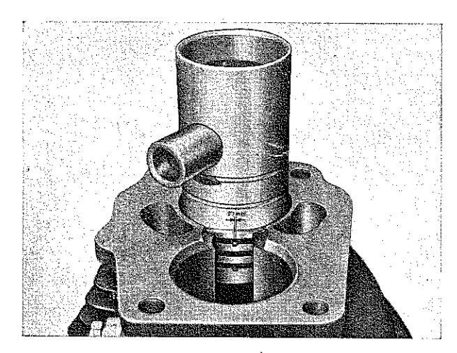
Fig. 19: Gap of piston rings
- 3. Check gasket of cylinder base flange; if necessary, fit a new one and soak it well in oil. Put some oil on cylinder wall. Turn piston rings until the locking pins appear in the gap between the butts. Only when all piston rings are in their correct positions, may the cylinder be put on. Oil the pistons, get them into a position as much parallel to each other as is possible and put the cylinder in place. We would again stress the importance of a correct positioning of the piston rings, because if they are not properly placed, they may break when the cylinder is mounted.
- 4. Before screwing down the cylinder base flange screws and while the cylinder can still be moved, rotate the crankshaft slowly a couple of times in order to ascertain unobstructed movement of the pistons. Then screw down uniformly the diagonally opposed cylinder base flange srews.
Generator
- 1. Put on armature (fig. 2/2) and screw up lock screw lightly.
- 2. Install stator and tighten both screws.
- 3. Adjustment of ignition. (See also "electrical equipment".)
- 4. Tighten armature fixing screw, pull out pin for ignition adjustment, check ignition once more, insert carbon brushes. Close hole for the ignition adjustment pin by means of the screw plug.
Cylinder Head
Insert a good gasket, put on cylinder head and screw it down. When tightening the cylinder head screws, always screw down the diagonally opposed screws uniformly (from inside to outside).
If a reground or new cylinder with new pistons is assambled, the engine has to be run in like a new one. Also new piston rings require about 500 km (300 miles) of running-in.
Filling up with oil
When reassembling is finished, fill the engine up with oil (3/4 litre, about 1.5 pint). Oil must flow from the oil-level plug (fig. 18/8) when you check it.
ASSEMBLY INTO FRAME
When the engine has been lifted into the frame,
- 1. the two rear mounting screws are inserted from the right,
- 2. then the four fixing screws are put into the right-hand tongue of the front engine support and at the same time into the two eyelets in the frame and into the two eyelets in the engine block. (Mind the crank of the tongues! Engine is tilted out of center to the right.) The further assembly is done in the reversed order of dismantling.
3. Connect cables with generator.
Red cable (30) to central terminal (battery) White cable (61) to right-hand terminal (control signal lamp)
Black cable (1) to left-hand terminal (Ignition) Should, after a long time of operation, the colors on the cables no longer be clearly distinguishable, proceed as follows:
Connect battery to ground, insert ignition key, then touch each cable with the ground for a moment. The cable showing a bright spark (direct short-circuit) is the plus cable (30).
The cable producing a blue-purple spark is cable (1).
The cable lighting up control signal lamp of head light is cable (61).
After all works at the oil pump and whenever the oil hose has been disconnected, the enclosed air within the hose is to let out, that means, the connecting screw of the oil hose at gear-box should be tightened, after oil had started to flow from there.
ADJUSTING THE CARBURETTOR
The varied quality of fuels may necessitate an alteration of the carburettor adjustments, but we
should not recommend doing that on a new machine before it has been ridden for about 600 miles. New engines have slightly higher consumption which must not be decreased by using a poor mixture. i. e. a mixture containing too little gas. The screw for regulating idling speed (fig. 20/2) should not be applied for setting idle running at random. As the influence of this screw up to about 38 mph is very great it should be applied in this speed range for the purpose of regulating the consumption. If the consumption rises above the ratio. unscrew air-screw for idler. An air-screw entirely screwed up causes rich (fat) mixture (excessive consumption). If the air-screw is loosened consumption will drop immediately. Therefore it is advisable to loosen the screw by quarter turns only If the result is not satisfactory continue to unscrew for another quarter turn etc. The efficiency will decrease after a full rotation. No effect will be obtained by unscrewing it more than 21/2 turns. If one hears banging noises from the carburettor


while riding slowly with a warm engine, while slowly opening out the throttle or while slowly shutting the throttle, the mixture is too poor. Then the air adjusting screw has to be screwed up by quarter turns, until the noises have stopped. It
may occur that the engine refuses to pull with a scanty setting of the tarburettor, when the throttle is slowly opened from low speeds. In such a case the air-adjusting screw must also be screwed up until the engine accepts gas regularly.
If in spite of this procedure there is still excessive consumption or if hanging noises are heard from the carburettor, set iet-needle as required. To decrease consumption clamp needle with the needle holder into the next groove. To give an example. Has the needle been clamped into the 4th groove (normal adjustment) then it should be clamped into the 3rd groove (again from top end). When the jet-needle has been adjusted, the air-screw must again be regulated in the manner described above. Concerning the carburettor setting for idling, it must be set so that with the twist grip fully turned off the engine must run in neutral at moderate revs. If the idling position is not set properly trouble with the plug may occur. The adjusting-screw for idling will be found on figure 20/3. Don't bother to set the lowest number of revs. obtainable for idling. The engine, if running idle, should run smoothly. moderately and steadily. On no account should it be allowed to stop, even when the engine is hardly warm. We point out once more that the airadjusting screw must not be adjusted any more when the gas for idling is set For perfect functioning of the carburettor the crossbore in the top part of the needle-valve is absolutely transverse to the direction of the carburettor passage. When exchanging the needle valve, take care to select one that guarantees proper position to the cross section bore, if screwed up. Trifling differences can be corrected by inserting a thin ring gasket of 0.00787 in. at most, otherwise the opening of the iet tube would be placed too low. which would cause a change in the composition of the mixture. Two-stroking engines require larger main jets in the hot season. The fitted main jet No. 150 (fig. 20/4) is suitable for exerting rides in summer. In winter use main jet No. 145. If the engine runs more quickly with main jet No. 145 in the hot season. its use is admissible also in summer.
Signs of wear of the carburettor parts usually proclaim themselves only after a very long period of use and it is altogether wrong to try and remedy unsatisfactory performance by altering carburettor adjustment. Abnormal consumption figures are also very likely to be caused by the engine, in which case it would be wrong to try and remedy it by altering the carburettor setting. Use as much as possible the normal carburettor adjustment only.
Part 3
CHASSIS
Handlebar
a) Detaching handlebar
- 1. Remove twist grip: Loosen the two fastening screws (fig. 21/1) and remove half the casing (fig. 21/2). Thereafter pull the twist grip from the handle bar. Now the nipples (fig. 21/3 & 21/4) for the carburettor and oil pump control cables can be unhinged. The cover (fig. 21/5) can be separated from the casing half (fig. 21/6). Both nipples can be pulled through the resulting opening.
- 2. Unscrew dimmer switch.
- 3. Loosen clutch cable by unscrewing the adjusting screw of the clutch lever (fig. 2/1) and detach clutch cable from handlebar.
- 4. Detach brake cable first from the lever of the front wheel brake and then from brake handlebar.

Fig. 21: Twist grip
| 1 | Fas | sten | ing | screw |
|---|---|---|---|---|
| 2 | Casing | half | |
|---|---|---|---|
| 2 | Minnle |
6 Casing half 7 Slot screws
5 Cover
-
4 Nipple
- 5. Unscrew cover of bridge-piece of the fork and detach handlebar.
b) Reassembling the handlebar
- 1. Reassembling is performed in reversed order of dismantling Grease all sliding parts of the twist grip well.
- 2. The small screw of the twist grip shell (fig. 21/7) serves to brake the movement of the twist grip, if it shows a tendency to return automaticaly.
Front wheel springing
-
a) Dismantling the telescopic fork
- 1. Remove front wheel, unscrew fender nuts and detach fender downwards after turning the (legs) of the fork forward.

Fig. 22: Adjusting nuts of the steering bearing 1 Nut of the clamping 4 Top bridge-piece of
- Lock nut 5 Dust cap
- 3 Adjusting nut
- 2. Detach positive cable from battery terminal.
- 3. Unscrew cover ring from headlamp body, disconnect the six cables forming the headlamp cable assembly and pull out the latter. Unscrew dimmer switch from handlebar. Unscrew union nut of flexible speedometer drive and pull out shaft. Dismantle headlamp.
- 4. Extract split-pin from steering damper, unscrew handwheel and detach same. Unfasten forward tank attachment screw and detach friction discs of steering damper.
- 5. Detach hand-brake cable, unscrew cover of top bridge-piece of fork and lay handlebar back upon the tank.
- 6. Loosen the two clamping screws for the fork legs at the top bridge-piece (fig. 22/4), unscrew cap nuts (fig. 23/7) and plug screw of the top end of the fork (fig. 23/8), loosen nut of the clamp screw (fig. 22/1) and unscrew check nut (fig. 22/2) and adjusting nut (fig. 22/3) (by using spec. tool 250.7012). Lift off top bridge-piece (fig. 22/4), using a rubber mallet. (The dust cap, fig. 22/5, is pressed into the bridge-piece together with the bearing cone, so that these two parts are
removed with it.) Then pull out the fork. While doing so, care must be taken not to lose any of the 18 balls of the bottom bearing of the steering head.
b) Assembling the Telescope Fork
Renew worn steering shells. New balls (18 each) should be provided for new shells. The shells should be pressed into the tube of the frame up to their collars. Do not cant them!
Assembly in reversed order of dismantling. To tighten the lock nut (fig 22/2) the adjusting nut (fig. 22/3) must be held by tool No. 250.7030. Connecting the five cables forming the cable assembly of the headlamp: see wiring diagram.
When the cables have been connected, reconnect battery.

Fig. 23: Telescope leg dismantled
1 Screw
- 2 Union nut
- 3 Seal ring
- 9 Leg tube ng 10 Buffer ring
8 Plug for top end of fork
-
4 and 5 Bronze bushing 6 Plug for bottom end
- Plug for bottom end of fork
c) Taking to pieces the Telescope Fork
Take off frontwheel, remove fender (mudguard). Complete dismantling for detailed examination (The fork need not be detached from the machine):
- 1. After removal of the knock-out axle the screw situated inside the eye at the end of the fork (fig. 23/1) has to be loosened and tapped into the fork (place vessel underneath to catch oil flowing out). Then the screw is unscrewed completely.
- 2. Now pull down sliding tube until union (fig. 23/2) becomes accessible. This union is unscrewed (use special tool No. 250.7021). Pull off sliding tube downwards.
A ring seal (fig. 23/3) is situated inside the union (fig. 23/2). If any oil issues from the fork, this seal ring must be exchanged for a new one.
3. Check the bronze bushings (fig. 23/4 and 23/5) and renew them if they show a radial play of about 0,0394 in. (1 mm).
These parts are dismantled after the plug for the bottom end of the fork (fig. 23/6) has been unscrewed.
Further dismantling
4. Unscrew both nuts at the top end (fig. 23/7 and 23/8). Pull out the pressure spring together with its supporting tube, loosen the clamp screws of the fork tubes at the top and bottom bridge-pieces and finally pull out the legs (fig. 23/9) in a downward direction. Headlamp bracket and exterior tube can now be detached.
d) Telescope Fork Reassembling
Reassembling is done in reversed order of dismantling. Insert leg tubes in such a way that the top oil holes in both of them face forward. When reassembling, slip rubber buffer ring (fig. 23/10) on leg tube before fitting the bronze bushings.
After reassembly put 5 cu. in. of oil into each tube.
Rear Wheel Springing
a) Dismantling the Telescopic Strut
Unscrew securing worm screw (fig. 24/1) at bottom end, remove joint bolts at top and bottom ends of strut and take out the telescopic strut.
b) Reassembling in reversed order
c) Taking apart Telescopic Strut
Removal of the damper cylinder for renewing its oil.
A 15
Put screw spapner (clearance 22 mm) through the turns of pressure spring (fig. 24/2) and unscrew sealing screw (fig. 24/5) by means of the above montioned snapper
Pull telescopic strut apart. Now empty damper cylinder (fig. 24/7) and fill it up with fresh damper oil (47/, cu.in.). Reassembling in reversed order of dismontling
Placing the damper cylinder, take care the little hole of damper cylinder showing to bottom.
After unscrewing the damper piston and dismantling the sealing screw grooved ring sleeve can be changed without any special tool.

Fig. 24: Rear suspension shock absorber
1 Top strut head 2 Pressure spring Bolt of piston 5 Sealing screw
- Damper piston Damper, cylinder
- 8 Bottom strut head
-
d) Detaching the pivoted swing fork
- 1 Remove rear wheel detach chain guard open chain and pull it out unscrew puts of clamping shells and take out clamping shells and chain sprocket carrier, unscrew bracing plate underneath the connecting tube of the two swing arms from the frame, and finally detach telesconic struts
- 2. Unscrew lock nut and nut of the swing fork shaft, remove clamp disc and rubber disc and pull out shaft. By pushing aside the two cover rings the two discs lying between the swing arms and the bearing tube of the frame are released and drop out. Then the swing fork can be taken out in a downward direction.
e) Assembling the swing fork
Assembling in reversed order of dismantling. Do not forget to insert the spacers between swing fork and bearing tube of the frame and to cover them with the rubber rings
Uube
-
a) Dismantling the bearings
- 1. Right-hand side: Press out rubber seal ring with a screwdriver, remove snaping. In the spacer tube keeping the two ball bearings at the correct distance there are two recesses. Insert a mandrel in this recess and press out the right-hand ball bearing from the left.
- 2 Left-hand side: The left-hand hall bearing is pressed out from the right by means of a mandrel.
-
b) Reassembling the bearings
- 1 Bight-hand side: Insert guide washer (see fig. 25). Grease and press in right-hand ball bearing, fit snapring, Press intermediate ring into seal ring and press seal ring into hub. The sealing edges of the seal ring must face inwards.
- 2. Left-hand side: Fit spacer tube, insert guide washer, grease and press in ball bearing. Press in seal ring (sealing edges facing inwards).
c) Chain sprocket carrier
- 1. Dismantling the bearings: Detach outer snapring from the stub of the clamping shell facing the hub, press out clamping shell, remove seal ring near chain sprocket and both interior snaprings retaining the outer ring of bearing, and press out the bearing.
- 2 Assembling the bearing: Pressing in the bearing is done from the side of the hub, since the seat of the bearing is conical. Before

Fig. 25: Rear Wheel Hub
pressing in the bearing insert interior snapring at the side of the chain sprocket to form a stop for the bearing, as otherwise the bearing might be pressed through. After pressing in the bearing fit interior snapring at the side of the hub as a stop for the bearing. Mount seal ring facing the chain sprocket, press in clamping shell and fit its securing outer snapring. Grease the bearings amply.
3. When the six retaining bolts of the chain ring have been unscrewed, it will be easy to lift off the flexible coupling. The arrows marked on the flexible coupling should always point in the direction of wheel rotation, i.e. in a counter-clockwise direction.
Fuel Tank
a) Dismantling
1. Remove oil pipe and allow oil to run into some vessel, drain petrol (gasoline) from fuel tank by means of a hose, pull petrol pipe from the carburettor, detach connecting hose between the two tank halves.
- 2. Unscrew nut of the forward attaching screw and remove screw (be careful of the spacers), unscrew lock nut and nut of the rear tank attachment and knock out screw by a few light taps until retaining discs (collar discs) release the flaps of the fuel tank, so that the tank can be detached while the rider's saddle is being pressed downward.
- b) Assembly in reversed order. Do not tighten the rear nuts before the collar discs have engaged with the flaps of the tank.
Center prop stand
a) Dismantling
Detach spring by means of screw driver. Pull out one of the screws, press against the other one and pull out tubular spacer with the second screw. Then detach center prop stand.
b) Assembly
Hold stand in place, insert tubular spacer, tighten screws (with spring washer) of the tubular spacer. Hitch up spring by means of a wire loop.
6 - 16
Part 4
ELECTRICAL EQUIPMENT
Battery-Ignition Lighting
Battery ignition is particulary suited for good starting, supplying as it does an intensive ignitionspark at lowest r. p. m. Easy starting and rapid "get-away" are features which every motor cyclist will always appreciate. And this primarily involves proper care of your battery.
Battery
A new battery has first to be filled-up with chemically pure sulphuric acid of 32° Bé (Baumé). It is then left to "soak" for 3 hours. After that it will be checked whether or not the battery indicates voltage (8 V). If it proves so, that battery is ready for use, otherwise it will have to be charged from a D.C.-source of 0,7 ampere. Continue charging until gas evolves uniformly from all plates and a terminal voltage of 2,7 V per cell has been reached. The density of acid is decreased by the soaking, but should be 32° Bé again, after charging.
There must always be enough acid in the cell to keep the acid level 0,1181 in. to 0,1574 in. (3 to 4 mm) above the top edge of the plates (not the edge of the insulating separator plate) or until acid level is just visible from open hole in splash plate. Spilled acid must be replaced by fresh acid, evaporated acid however, must be compensated for by replenishing battery with distilled water only. Tap water would ruin it! Check level every fortnight. Evaporation is most intensive during hot season. When acid level has dropped below top edge of plates, a further drop of level takes place rather rapidly, on account of the narrow section of acid flow between plates. Thus, another 0.244 cu in. (4 ccm), of evaporated acid result in a further drop of level of 0.3937 in. (1 cm). Too high a charging-current, as well as too low an acid level (or insufficient density of acid) tend to cause the substance of the positive plates to get mellow and to crumble. The battery having been charged, wipe top surface of battery quite dry and give terminals a coating of acid-free vaseline. Should terminals show signs of oxidation. clean and grease them at once. Should the model be laid up (e.g. for winter, and so on) don't under any circumstances fail to have the battery recharged every month. When installing the battery in your motor cycle remember to connect your cables correctly, put (---) terminal of battery to ground as in case of a mistake this would cause a reversal of the polarity of the dynamo (generator), and subsequent damage to both generator and battery. Don't use force while
connecting your cables to the terminals, as this might to break the latter.
Preparing 7 amp./h. motor cycle batteries, precharged an dispatched in dry condition, for operation. The great advantage of precharged batteries is that they are ready of operation within a very short time after filling.
How to prepare them for operation:
The dry battery is filled with chemically pure sulphuric acid of 1.28 spezific weight and then left to soak for at least three hours. After that period the acid level is checked and, if necessary, adiusted. It schould be 5 mm (= 1/s in) above the top edge of the plates. Then recharging is started, for which any source of D.C. can be used, the positive note of the current source being connected with the positive terminal of the battery. Amperage of the charing current should not exceed 0.7 amp. but can be lower than that. Recharging will, in most cases be finished after a few hours. The dry precharged batteries have a limited storage stability. For quite fresh batteries a recharging period of two hours will suffice. With older batteries the charge diminishes gradually so that one has to allow for a longer charging period. The density of the acid drecreases when the filled battery is left standing, depending on the degree of self discharge owing to long storage. Therefore charging is to be continued until the acid has regained its original density and the positive and negative plates evolve gas uniformly. As self-discharge occurs irregularly, one type of plates will begin evolving gas sooner than the other one. Since it is impossible to observe the formation of gas on the individual plates the conclusion of the charging process is ascertained by checking the voltage as well as by measuring the acid concentration. Charging may be regarded as finished when the density during charging has reached 1.28 again and when the voltage during charging with 0,7 amp. has risen to 8-8,3 volt and does not go on rising. These voltage values only apply to a temperature of 20° C, as they are higher at lower temperatures and vice versa and, in addition, are liable to vary to some degree. The important fact is that neither acid density nor charging voltage continue to rise beyond a certain point.
Attention! Use only chemically pure sulphuric acid. If it is concentrated, dilute only with distilled water! Always pour acid into water, never the other way round! Impure acid and impure water will ruin the battery in a very short time.
The acid must be carefully kept on the required level. If it is too low acid of the same density as the one in the battery has to be added. Only when the acid density is too great (i. e. above 1.28 in the fully charged battery) distilled water should be added. Often it will prove necessary to fill up with acid and not with water, because gassing throws out more acid than water is decomposed.
Summary:
- 1. Fill up with sulphuric acid (1.28 density).
- 2. Leave battery standing for at least three hours.
- 3. Correct acid level (it should be 5 mm = 1/5 in. above top edge of plates).
- 4. Recharge with a maximum of 0,7 amp. until acid density and voltage (8---8,4 volt) stop rising and both types of plates evolve gas.
Ignition key:
The ignition switch is housed in the headlamp. As soon as the key is inserted, the lamp for the charging control of the generator will light up. Extinguishing of lamp indicates that generator is connected parallel to battery and that current is being fed by the dynamo. Should the lamp remain lighted while the engine is running, this is an indication that there is either something wrong or that revolutions are too low. If riding at night at less than 25 m. p. h., use 3rd speed, or the battery will be completely discharged. Don't ever forget to detach ignition key when stopping your engine, because if you don't the battery will be completely discharged within half an hour.
Generator:
Whenever any work has to be done on the electrical equipment do not fail first to disconnect lead (30) from the positive (+) pole of your battery. Once the cover of the dynamo has been taken off, all parts are easily accessible. The accumulated carbon dust should be removed by means of a clean, dry paint brush and blown away.
See to it that carbon brushes (Fig. 26/5) can be moved freely in their grooves.
When owing to a short-circuit, the braided wire of the carbon brushes has become unsoldered, splashes of tin will show on the commutator. Then don't fail to consult immediately an experienced electrician. Also note that iron filings (dust) when dropped into the voltage regulator (1) lead to functional disturbances of the latter. Burned breaker contacts (4) should be smoothed off with small file. The lubricating felt-pad (2) of the contact-breaker cam should be soaked with best heat resisting bearing grease or two or three drops of engine oil every 1300 miles or so. Intensive sparking at the breaker-contact indicates condenser (3) trouble.
When connecting the leads, the braided wires of the cable ends should be carefully (and cleanly) turned in, as projecting wires might easily cause a short — circuit.

Generator and Voltage Regulator:
The 4-pole D.C. shunt wound generator consists of two main parts: 1) the armature which is attached (without cotter pin) to the crankshaft and carries the cam for the make-and-break contact and (1) the polehousing incorporating the field windings, the make-and-break contact of the ignition, the condenser and the voltage regulator. All these parts are arranged as a unit on the engine housing. A Bosch system of voltage regulator is used for our machines.
Adjusting of the regulator RS/ZA45-60/6/4
Although every new regulator is correctly adjusted, it is neccessary to check the adjustment again after the fitting in warm condition for an event. readjustment. This work is described in the following:
Neccessary is an electro dynamic volt meter with a measuring capacity of 0—10 or 0—15 volt and an ampere meter with a measuring capacity of 10—0—10 ampere.
1. Measuring the idling voltage of the generator with disconnected current consumer:
- a) Take off cover of the generator; on the terminal plate there are 3 clamps no. 1.30/51 and 30/61. Disconnect red cable from the middle clamp 30/51. Connect the plus pole of the volt meter to the free clamp 30/51. Connect negative pole of the volt meter to the earth of the motor vehicle.
- b) Start the engine (the ignition coil is supplied with current from the accumulator) Read the voltage of the volt meter at about 2000 to 2200 and at about 4000 r. p. m. At very speed range the volt meter has to show 7.6 volts.
If the voltage is lower than 7.6 volt the accumulator will be discharged at slow driving resp. at night. If the voltage is exceeding 7.6 volt, the battery will get to much charging current and the result will be an overflowing of the acid, an abnormal wear of the carbon brushes and the collector.
c) If the volt meter does not register any voltage, the carbon brushes have to be checked for easy movement in their holders and also that the regulator is switched on. If it has to be connected by depressing with a finger, the cut out current has to be readjusted (see further below).
2. Adjustment of the voltage regulator:
Adjusting or checking the regulator is possible only in warm condition.

Fig. 27: Adjustment of the regulator
- a) Before readjusting oxidized or burnt contacts have to be cleaned with a very fine contact file
- b) Adjusting of the idling voltage.
- Contact the volt meter as prescribed and

Fig. 28: Adjusting of the voltage regulator with adjusting tool Pos. 905.0.32.601.2
read the idling voltage. If the voltage is below 7.6 volt, the regulator contact armature has to be bent slightly in the direction marked with plus (fig. 27), by means of the adjusting tool Pos. 501.1.55.056.2 (see fig. 28/2), thus increasing the idling voltage, until reaching 7.6 volt.
Bending in the direction marked with minus, reduces the idling voltage.
If the regulator is adjusted correctly to 7.6 volt idling voltage, the generator will supply the battery with the exact charging current, because it is depending only on the charging condition of the battery.
The charging current of a completely charged accumulator will be 1 to 1.5 ampere, a low charged battery will come from 3 to 4 ampere. Therefore, the adjustment of the regulator should never be done by using an ampere meter. The only permissible checking method to apply an ampere meter is the following:
Connect in series an ampere meter between the plus or negative pole of the accumulator.
At running engine and switched on head lights a fully charged accumulator (check acid density) has to be charged from 0.2 to 0.4. In every other case the idling voltage can be raised to 7.8 volt.
3. Adjustment of the cut out current.
Connect in series an ampere meter with a charging and discharging measuring capacity of 10-0-10 ampere between the plus or negative cable of the accumulator. After starting the motor the discharging current is registered (at low r. p. m. idling gear).
By gradually opening the throttle engine r. p. m. are increased until the ampere meter shows the maximum charging current (using a fully charged accumulator). Then pull out the ignition key.
The revolutions of the engine will slow down. The charging current decreases — the ampere meter needle will approach and pass over the zero position and jump back to the zero position suddenly after reaching a specific discharging current capacity.
At this moment the regulator ist disconnecting the accumulator from the generator. The ampere meter reading at the moment of disconnection is the cut out current and is amounting to 4 and 6 ampere (can be reduced in special cases to 2—6 amperes).
If the cut out current is below 4 and above 6 ampere, the regulator armature has to be bent slightly with the adjusting tool Pos. 501.1.55. 056.2 (see fig. 20/2) until the ampere meter reading of 41/2 to 51/2 ampire is obtained. Slightly bending in the direction marked with plus raises the cut out current. Slightly bending in the direction marked with minus reduces the cut out current (fig. 27).
The correct adjustment of the cut out current is very important, and is of eminent influence to the charging process.
If the regulator contact ist cutting out too early (cut out current below 4 ampere) current will he consumed from the battery so at low speed or while driving at night the battery will be discharged.
If the regulator contact is cutting out too early (cut out current over 6 ampere) the accumulator will be discharged by the dynamo. Moreover there is the danger that the armature of the regulator becomes sticking to the magneto due to the remanent magnetism, when pulling out ignition key.
By doing so, battery will be discharged in a verv short time.
We want to point out once more, that the regulator must not be adjusted with the ampere meter alone. as the charging current depends on the charging condition of the accumulator. which in most cases is unknown
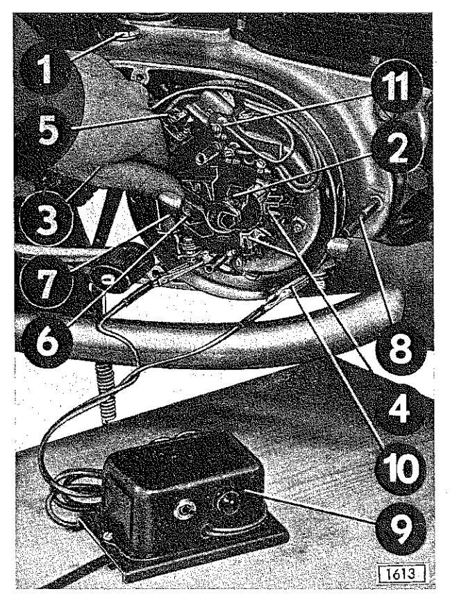
Fig. 29
- Oil filling screw
- 3 Adjusting screw 4 Carbon brush
- 6 Contact breaker
- 7 Condenser 8 Adjusting pin 9 Ignition timing tool 10 Clamp of test lamp
- 11 Disconnected wire
Adjustment of ignition
The ignition should take place 0.256 in (6.5 mm) before reaching top dead center. (Measured at rear piston.) When checking, first of all unscrew sparking plug and remove cover of dynamo. Now the crankshaft can easily be turned with a snanner which is put on hexagon-headscrew of the holdingdown screw for armature. After having done that mind that the distance of the contact breaker if completely opened is 0.01575 in (0.4 mm) Exact advance sparking will be obtained if you put pin for ignition adjustment (No. 250.7027) into the control opening at engine base in order to lock crankshaft. The pin fits into a slit for adjustment. In this position the ignition cam just starts disconnecting contact-breaker. If ignition is incorrect, take out carbon brush, and unscrew armature screw and loosen armature with the extractor (Pos. 22733) so that it can be shifted. Turning it against the rotation of the engine will result in more advance sparking, turning it with the rotation will reduce it. Exact adjustment may be obtained by correcting the distance of contact breaker within the limit of 0.0148 in. (0.38 mm) up to 0.0164 in (0.42 mm)
The opening of the contact breaker at the exact moment can be checked with:
an ignition timing tool (p. e. Bosch EWAF 87).
Connect one cable of the ignition timing tool to the contact lever, the second cable connect to the earth. Switch on the instrument. The instrument produces a weak buzzing sound and the control light glows faintly. By turning the rotating armature in the sense of engine rotation, the buzzing sound becomes stronger and the control light begins to glow brighter at the moment the contact breaker points begins to open.
a control lamp
Two cables are soldered to (+) pole and (-) pole of a hulb of 6 V/1-3 W Disconnect at the conpecting plate cable (1). Then connect one cable of the test lamp to terminal 30/51. while the second cable is connected to the contact breaker Having done this the armature is turned counterclockwise until contact breaker is closed. If this happens the lamp lights up. Now continue turning the armature in the same direction, until the lamp is extinguished which indicates the exact point of ignition.
Adjusting Beam of Headlamp
The adjustment of the light has to be in accordance to the prescription of law. After loosening the tightening screw he complete headlamp is moveable in order to be adjusted.
Load the motor cycle with one person and adjust the head light only, then you will receive the proper "low beam position" automatically.
Adjust as shown at the sketch below. For this purpose it is necessary to designate a wall (see sketch) for adjustment of the high beam position.

Fig. 30: Motor cycle position with respect to wall
Section 7 SPARE PARTS LIST
| TABL | E OF | |
|---|---|---|
| ENGINE | 0 | Crankcase, Cylinder |
| ( | Ø | Engine Parts, Oil Pump |
| 0 | Clutch | |
| 0 | Gearbox | |
| Θ | Kickstarter, Speedometer Drive | |
| 0 | Gear shift, Electric idle gear indicator | |
| Ø | Carburettor P 32/1 | |
| 0 | Exhaust | |
| CHASSIS | 0 | Fuel tank, Twin seat |
| 0 | Frame | |
| 0 | Central prop stand, Foot brake, Foot rests | |
| Ø | Pivoted rear fork, Chain guard | |
| © | Rear Suspension Shock Absorber | |
| Ø | Fenders, Tail-stop-light group | |
| FORK | Ð | Front fork and steering assembly |
| ❻ | Handlebar, Bowden cables | |
| ROAD WHEELS | Ø | Front wheel |
| ـ | Rear wheel, Rear chain | |
| ELECTRICAL EQUIPMENT | ً | Generator |
| Head lamp with electric idle gear indicator, speedometer, battery, horn, ignition coil | ||
| EXTRA EQUIPMENT | Ø | Tools |
| APPENDIX | Ø | Accessory Exhaust kit |
| Ø | Special Tools |
To convert millimeters to inches, multiply by 0.03937
Model Number 810.89571 for Vehicles which are laquered poppy-red — silver Model Number 810.89572 for Vehicles which are laquered black — silver

7 — 2

CRANKCASE, CYLINDER
| R |
ef.
lo. |
Part No. | Description |
Requd.
No. |
|---|---|---|---|---|
| 1 | 250 1007 | Cylinder head cap screw M 8X65 — 8 G | 8 | |
| 2 | 2/804 | Washer 8.4 DIN 433 | 8 | |
| 3 | SEARS No. 60400 | Spark plug | 2 | |
| 4 | 253.1001 | Cylinder head | 1 | |
| 5 | 253.2.1004 | Cylinder head aasket (Alu) | 1 | |
| 6 | 253,1005,2 | Cylinder, normal, 45 mm dia. | 1 | |
| 6 | 253.1005.3 | Cylinder, 45,5 mm dia. | ||
| 6 | 253.1005.4 | Cylinder, 46 mm dia. | ||
| 7 | 900.2009 | Hexagon nut M 8 DIN 934 8 G | 4 | |
| 8 | 250,1013 | Cylinder base flange gasket | 1 | |
| 9 | 900,1204 | Fillister head screw M 7X25 (DIN 83) | 2 | |
| 10 | 25918 | Fillister head screw M 7X50 (DIN 83) | 1 | |
| 11 | 25917 | Fillister head screw M 7X55 (DIN 83) | 4 | |
| 12 | 25410 | Fillister head screw M 7X38 (DIN 83) | 5 | |
| 13 | 128.1062 | Stud bolt (for chain lubrication) | 1 | |
| 14 | 250,1041.2 | Venting screw | 1 | |
| 15 | 26526 | Seal ring C 18X22 DIN 7603 | 2 | |
| 16 | 253,1044 | Oil filler plug M 18X1,5 | 1 | |
| 17 | 250.1009 | Packing for oil-pump adjusting hole | 1 | |
| 18 | 250.1008 | Cover for above | 1 | |
| 19 | 23319 | Hexagon head screw M 5X12 DIN 933 | 2 | |
| 1 | 20 | 900.1305 | Fillister head screw M 6X8 DIN 84 | 1 |
| 21 | 24365 | Seal ring A 6X12 DIN 7603 | | 1 | |
| 22 | 900,1902 | Stud AM 8X18 DIN 835 8 G | 8 | |
| 23 | 900.1918 | Stud AM 7X12 | 4 | |
| 24 | 24573 | Spacer 9 mm dia., 16,5 long | 2 | |
| 25 | 250.1034 | Left crankcase cover | 1 | |
| 26 | 16636 | Seal ring 14/10,5/1,5 | | 1 | |
| 27 | 250.1010 | Hexagon head screw for oil level plug | | 1 | |
| 28 | 24554 | Packing for crankcase lid | 1 | |
| 29 | 171.1.10.010.1 | Lid | | 1 | |
| 30 | 25429 | Lens head screw for lid AM 5X12 DIN 85 | 2 | |
| 31 | 253.1046 | Oil drain plug (M 8) | | 2 | |
| 32 | 26482 | Seal ring A 8X14 DIN 7603 | 3 | |
| 33 | 26218 | Lens head screw M 6X50 DIN 85-8G for left crankcase cover | 6 | |
| 34 | 253,1050 | Crankcase gasket | | 1 | |
| 35 | 254.1032.0 | Crankcase complete | 1 | |
| 36 | 900,4801 | Cylindrical pin 6 h 8X36 DIN 7 | 2 | |
| 37 | 250.1049 | Gasket for crankcase cover | ||
| 38 | 26370 | Hexagon head screw M 8X8 DIN 933 for oil drain | | 1 | |
Downloaded from www.Manualslib.com manuals search engine


ENGINE-PARTS, OIL PUMP
|
Ref.
No. |
Part No. | Description |
Regud.
No. |
|---|---|---|---|
| 1 | 253 1060 | Pieton ring AZ 45X2.5 ac DIN 73102 | 6 |
| 253,1060.3 | Piston ring oversize J. AZ 45.5X2.5 ac DIN 73102 | ||
| 253,1060,4 | Piston ring oversize II. AZ 46X2.5 ac DIN 73102 | ||
| 2 | 175 1008 | Notched securing pin 2.5X7 | 6 |
| 3 | 253,1006.2 | Piston, normal, 45 mm dia. | 2 |
| 3 | 253.1006.6 | Piston oversize 1, 45,5 mm dia. | |
| 3 | 253.1006.7 | Piston oversize II, 46 mm dia. | — |
| 4 | 250.1011 | Piston pin 18 mm dia., 36 mm long | 2 |
| 5 | 13970 | Snap ring Sg 18x1 DIN 472 | 4 |
| 6 | 253.1015.0 | Crankshaft compl. with connecting rod | 1 |
| 7 | 26020 | Deep-row ball bearing 6305 62/25/17, DIN 625 for crankshaft | |
| left side | 1 | ||
| 8 | 250.1036 | Seal ring B 1 35/25/7 for crankshaft left side DIN 6503 | 1 |
| 9 | 250.1029 | Worm drive for oil pump | 1 |
| 10 | 900.6204 | Deep-row ball bearing 6204 47/20/14, DIN 625 for crankshaft | |
| left side | 1 | ||
| 11 | 250.1028 | Spring washer | | 1 |
| 12 | 26029 | Woodruff key 5X6,5 DIN 6888 | | 1 |
| | 13 | 26017 | Securing disc 32/16,5 mm dia. | | 1 |
| 14 | 26054 | Hexagon nut M 16X1,5 DIN 936 | 1 |
| 15 | 253,1030 | Engine sprocket, 22 teeth | 1 |
| 16 | 253,1040.0 | Front chain (Duplex, 64 rollers) | 1 |
| 17 | 900.1015 | Hexagon head screw M 6X35 SK DIN 931 | 2 |
| 18 | 250.1100.0 | Oil pump complete | |
| 19 | 250.1115 | Restoring spring | | 1 |
| 20 | 13584 | Spacer shim 34/25,5/0,1 | |
| 20 | 13584.2 | Spacer shim 34/25,5/0,2 for side of crankshalf (as needed) | - |
| 20 | 13584.3 | Spacer shim 34/25,5/0,3 j | - | |
| 21 | 900.6650 | Cylindrical roller bearing for crankshaft right-hand side NJ | |
| 00 | 05450 | Seal ring B 1 35/20/7 for crankshaft right-hand side DIN 6503 | 1 |
| 1 42 | 23132 | (identical with 250 1056) | 4 |
| 25 | 250 1053 2 | Buch 18/20/16 for main connecting rod and auxiliary connecting rod | 2 |
| | - | 230.1030.0 | Bear 19/20/10101 main connecting roa and downary connecting roa | 1 |
| 1 |


сготсн
|
Ref.
No. |
Part No. | Description |
Requd.
No. |
|---|---|---|---|
| 1 | 253.1201.2 | Clutch sprocket (51 teeth) | 1 |
| 2 | 253.1204.2 | Clutch hub | 1 |
| 3 | 251.1209 | Clutch hub stud (M 7, 50 long) | 5 |
| 4 | 250,1319 | Securing disc | 1 |
| 5 | 250,1320 | Nut M 18X1 | 1 |
| 6 | 251.1228 | Terminal clutch disc | 1 |
| 7 | 250,1212 | Interior disc | 6 |
| 8 | 250.1224.2 | Clutch friction disc (with lining) | 7 |
| 9 | 253.1212 | End clutch disc (with bent-up scallops) | 1 |
| 10 | 253.1210 | Clutch thrust plate | 1 |
| 11 | 251.1205 | Spring retainer cup | 5 |
| 12 | 251.1206 | Spring | 5 |
| 13 | 251.1207 | Collar nut (M 7) | 5 |
| 14 | 250.1214.2 | Clutch thrust bolt with button | 1 |
| 15 | 250.1216 | Sleeve 26/20/24 | 1 |
| 16 | 253.1217 | Thrust collar 40/20/2 | 1 |
| 17 | 22755 | Ball 5/16" | | 1 |
| 18 | 250.1215 | Clutch thrust pin 53 long | 1 |
| 19 | 250,1218 | Clutch release lever | 1 |
| 20 | 250,1219.2 | Base for clutch adjustment | 1 |
| 21 | 250,1222 | Securing spring | | 1 |
| 22 | 26819 | Spring ring B 8 DIN 127 | 2 |
| 23 | 900.1104 | Hexagon head screw M 8X25 DIN 933 | 2 |
| 24 | 250.1220 | Clutch adjustment screw (M 7) | 1 |
| 1 |
Sears 250 SGS --- 66/16 Downloaded from www.Manualslib.com manuals search engine


|
Ref.
No. |
Part No. | Description |
Requd.
No. |
|---|---|---|---|
| 050 4245 | 1 | ||
| 1 | 250.1315 |
Disc 00/0/0,70
Pubber real ring 48 5/7 5/2 5 |
1 |
| 2 | 250,1010 | Robber sear ring 10,0/7,0/0,0 | 2 |
|
১
, |
250.1510 |
Bouring Uvan
Dollon bearing for countershall right hand side and mainshaft |
1 |
| 4 | 200.1307.0 | noner bearing for countersnan right-hand side and mainsnan | 2 |
| [ | 250 4307 2 | Roller begring without begring bush | 2 |
| - | 250.1007.2 | Roller begring cage | 2 |
| 250,1300 | Cover for roller begring | 2 | |
| 900 6101 | Cylindrical roller 5X8 DIN 5402 | 18 | |
| 5 | 250 1306 | Thrust collar for countershaft and mainshaft 30/17/2 | 2 |
| 6 | 24288 | Spacer shim 25/18/0.1 as needed | | _ |
| 7 | 250 1304 2 | Countershaft dear 4th speed (17 teeth) | 1 |
| 8 | 250 1303 | Countershaft gear 3rd speed (15 teeth) | 1 |
| 0 | 250,1302 | Countershaft dear 2nd speed (12 teeth) | 1 |
| 10 | 250.1301 | Countershaft (8 teeth) | 1 |
| 11 | 25892 | Spacer shim 27/21/0,1 | |
| 11 | 25892.2 | Spacer shim 27/21/0.2 | | _ |
| 12 | 900.6304 | Deep-row ball bearing 6304 52/20/15 DIN 625 | | 1 |
| 13 | 250.1311.2 | Gear 1st speed (22 teeth) | 1 |
| 14 | 250,1312 | Gear 2nd speed (18 teeth) | 1 |
| 15 | 250.1313 | Gear 3rd speed (15 teeth) | 1 |
| 16 | 250.1314 | Mainshaft (13 teeth) | 1 |
| 17 | 26007 | Roller bearing WJL 47/20/18 DIN 5412 for mainshaft | 1 |
| right-hand side | | 1 | ||
| 18 | 25152 | Seal ring B 1 35/20/7 | 1 |
| 19 | 26029 | Woodruff key (cotter) 5X6,5 DIN 6888 | | 1 |
| 20 | 253.1325 | Gearbox sprocket (15 teeth)(series) | | 1 |
| 403.1.13.112.1 | · Gearbox sprocket (12 teeth) | | - | |
| 260.1328 | Gearbox sprocket (13 teeth) | | | |
| 20 | 253.1323 | Gearbox sprocket (14 teeth) only for special order | - |
| 253.1317 | Gearbox sprocket (17 teeth) | | | |
| 253.1324 | Gearbox sprocket (18 teeth) | ||
| 21 | 26017 | Securing disc 32/16,5 mm dia. | | 1 |
| 22 | 26054 | Hexagon nut M 16X1,5 DIN 936 | | 1 |
Sears 250 SGS --- 66/16 Downloaded from www.Manualslib.com manuals search engine
7 --- 9

KICKSTARTER, SPEEDOMETER DRIVE
| 曹门爵 | |
|
Ref.
No. |
Part No. | Description |
Regud.
No. |
|---|---|---|---|
| KICKSTARTER | |||
| 1 | 250.1328 | Spring plate | 1 |
| 2 | 250.1327 | Thrust spring | 1 |
| 3 | 250.1326 | Kickstarter dog, clutch gear | 1 |
| 4 | 253.1337 | Rubber pedal for kickstarter crank | 1 |
| 5 | 251.1340 | Kickstarter crank | 1 |
| 6 | 250.1342 | Bolt for kickstarter crank | 1 |
| 7 | 251.1341 | Hub for kickstarter crank | 1 |
| 8 | 250.1344 | Thrust spring | 1 |
| 9 | 250.1343 | Thrust bolt | 1 |
| 10 | 250.1346 | Ring washer cover | 1 |
| 11 | 250.1345 | Ring washer (rubber) for startershaft 25/16,8/4 | 1 |
| 12 | 250,1333 | Thrust collar 25/17,2/1 | 1 |
| 13 | 250.1331.2 | Kickstarter tooth segment | 1 |
| 14 | 250,1334 | Starter spring | 1 |
| 15 | 26529 | Snap ring Sg 14X1 DIN 471 | 1 |
| 16 | 250,1330 | Intermédiate gear of kickstarter | 1 |
| 17 | 250.1329 | Bolt for above | 1 |
| 18 | 250,1336 | Disc 46/16/1 for starter spring | 1 |
| 19 | 250.1335 | Fixing pin, pressure — sunk in housing | 1 |
| 20 | 28909 | Washer 14/6,5/1 for fixing pin | . 1 |
| SPEEDOMETER DRIVE | |||
| 253,1349.0 | Speedometer drive complete | 1 | |
| 21 | 26820 | Hexagon nut M 8X1 DIN 934 | 1 |
| 22 | 26819 | Spring ring B 8 DIN 127 | 1 |
| 23 | 251,1357 | Driving shaft | 1 |
| 24 | 250.1356 | Bushing 17/25 | 1 |
| 25 | 250.1359 | Securing pin 2 mm dia., 16 long | 1 |
| 26 | 253.1362.2 | Spindle bolt with driving gear (7 teeth) | 1 |
| 27 | 253.1361 | Worm wheel driven | 1 |
| 28 | 251.1359 | Securing pin 3 mm dia., 17 long | 1 |
| 29 | 26834 | Spring ring B 6 DIN 127 | 1 |
| 30 | 22872 | Hexagon head screw M 6x30 DIN 931 for attachment of | |
| speedometer spiral | 1 |

SEARS MOTOR CYCLE ------------------------------------
GEAR SHIFT, ELECTRIC IDLE GEAR INDICATOR

| 1 |
| 1 |
| 1 |
| 1 |
| 1 |
| 1 |
| 1 |
| _ |
| 1 |
| 1 |
| 1 |
| 1 |
| 1 |
| 1 |
| 1 |
| 1 |
| 1 |
| 1 |
| 1 |
| 1 |
| _ |
| 1 |
| 1 |
| 1 |
| 1 |
| 1 |
| 1 |
| 1 |
| 1 |
| 1 |
| 1 |
| 1 |
| 1 |
| | 1 |
| . 1 |
| 2 |
| | 1 |
| 2 |

7 --- 14

CARBURETTOR P32/1
| R |
ef.
Io. |
Part No. | Description |
Requd.
No. |
|---|---|---|---|---|
| - | 050 0 45 004 0/50 | 1 | ||
| - | | 253.2.15.001.0/50 | Carburenor compi., (winout air filler) | 1 | |
| 1 | 254.1.1551 |
1
2 |
||
| 2 | 20/// | Cap screw (M 5) | 1 | |
| 3 | 253.1549.2 | 1 | ||
| 4 | 253.1546 | 1 | ||
| 2 | 20039 | Spill pill 1 A to Dirk 74 | 1 | |
|
0 |
7 |
250,1500 | 1 | ||
|
/
0 |
250,1530 | Float | 1 | |
| 0 | 250.1525.2 | Carburattor bousing | ||
|
7
40 |
250.15/0.2 | Air filter compl. (0/116 mm dig. (with shackle) | ||
| 11 | 250.1543 | Shackle for air filter | 1 | |
|
11
10 |
230.1343 | Fillister head screw AM 6X 20 DIN 84-8 G | 1 | |
| 12 | 2/433 | Hexagon put M 6 DIN 934 | 1 | |
| 1.0 | 24773 | Bowden wire adjusting screw | 1 | |
| 14 | 26770 | Heragon nut (BM 6X0.75) | 1 | |
| 16 | 25/ 1 1519 | Cover for carburetter housing (24 high) | 1 | |
| 1 | 17 | 253 1532 | Cover for float chamber | 1 |
| 18 | 253 2 1 531 | Throttle piston thrust spring 15 mm dia., 90 long | 1 | |
| 180 | 254.1.1518 | Spring plate | 1 | |
| 19 | 253,1548 | Needie holder (clamp spring) | 1 | |
| 20 | 253 1516 | let needle | 1 | |
| 23 | 254 1.1515 | Throttle piston (50 high) | 1 | |
| 24 | 26776 | Guide screw | 1 | |
| 25 | 253,1521 | Flange gasket | 1 | |
| 26 | 253.1534 | Carburettor flange | 1 | |
| 27 | 29189 | Spring ring B 7 DIN 127 | 4 | |
| 28 | 24774 | Hexagon nut M 7 DIN 934 | 4 | |
| 29 | 253,1513 | Shoulder bolt (M 7) | 1 | |
| 30 | 253,1537 | Carburettor fixing shackle | 1 | |
| 1 | 31 | 250.1507 | 2 | |
| 31a | 253.1504 | Mixing jet | 1 | |
| 32 | 250.1510/40 | Idle jet No. 40 | 1 | |
| 33 | 250.1512 | Thrust spring | 1 | |
| 34 | 253.1511 | Regulating screw | . 1 | |
| 35 | 253.1520 | Thrust spring | 1 | |
| 36 | 253.1517 | Throttle piston stop screw (M 5) | 1 | |
| 37 | 250.1522 | Float chamber | 1 | |
| 38 | 900.3765 | Seal ring 24/17,2/1 | 2 | |
| 39 | 253.1508 | Needle jet | 1 | |
| 40 | 253.1509/14 | Main jet No. 150 | | 1 | |
| 40 | 253.1509/* | Main jet No (as required) | ||
| 41 | 250.1523.2 | Locking screw | 1 | |
| 1 |
* Please state jet number
Downloaded from www.Manualslib.com manuals search engine

|
Ref.
No. |
Part No. | Description |
Regud
No. |
|---|---|---|---|
| 253,1606,0/23 | Muffler right-hand side complete chromium plated | 1 | |
| | | 253,1607,0/23 | Muffler left-hand side complete chromium plated | 1 |
| 1 | 253,1629 | Connecting tube, 203 long | 2 |
| 2 | 900,4906 | Split pin 3X60 DIN 94 | 2 |
| 3 | 253,1617,0 | Silencer inner member complete | 2 |
| 4 | 253.1640 | Asbestos seal cord (rear) (3 mm dia., 250 long) | 2 |
| 5 | 27616 | Steel wool for silencer | 4 |
| 6 | 900.2105 | Hexagon nut M 5 DIN 555 | 10 |
| 7 | 29190 | Spring ring B 5 DIN 127 | 10 |
| 8 | 900,1308 | Fillister head screw AM 5X30 DIN 84 | . 10 |
| 9 | 24417 | Hexagon nut AM 6 DIN 439 | - 2 |
| 10 | 900.3937 | Washer 12/6,4/0,75 | 2 |
| 11 | 24365 | Seal ring A 6X12 DIN 7603 | 4 |
| 12 | 900,1511 | Lens head screw M 6X90 DIN 85 | 2 |
| 13 | 253.1635 | Asbestos seal cord (middle) | |
| (3 mm dia., 227 long) | 4 | ||
| 14 | 900.2106 | Hexagon nut M 6 DIN 555 | 2 |
| 15 | 26834 | Spring ring B 6 DIN 127 | 2 |
| 16 | 253.1625.2 | Shackle | 2 |
| 17 | 253.1636 | Asbestos seal cord (front) (2 mm dia., 227 long) | 2 |
| 18 | 900.1339 | Fillister head screw AM 6X35 DIN 84 | 2 |
| 19 | 255.1605 | Gasket for exhaust | 2 |
| 20 | 26819 | Spring ring B 8 DIN 127 | 4 |
| 21 | 24775 | Hexagon nui M 8 DIN 934 | 4 |
| 22 | 253,1601.2 | Exhaust pipe right-hand side | | 1 |
| 22 | 253,1602.2 | Exhaust pipe lefi-hand side | 1 |
| (23) | 253.1608.2/23 | Covering pipe right-hand side chromium plated | 1 |
| 23 | 253.1609.2/23 | Covering pipe left-hand side chromium plated | | 1 |
| 24 | 253.1622 | End pipe | 2 |
| 25 | 26834 | Spring ring B 6 DIN 127 | .2 |
| 26 | 900.1205 | Fillister head screw AM 6X50 DIN 84 | 2 |

7 — 18
FUEL TANK, TWIN SEAT
|
Ref.
No. |
Part No. | Description |
Regud.
No. |
|---|---|---|---|
|
1
2 3 4 4 4 4 4 4 4 4 5 6 12 12 14 15 16 20 21 22 24 25 26 27 28 29 30 31 32 33 35 36 37 40 41 42 43 44 45 46 46 46 46 46 46 46 46 46 46 |
270.3.22.000.2/90
360.1.22.520.0 270.1.22.023.1 270.2.22.023.1 270.3.22.028.1 270.3.22.028.1 270.3.22.028.1 270.3.22.029.1 270.1.22.127.0 128.2227.0 16636 27634 26793 24456 900.0902/07 900.0902/07 900.0902/07 900.0902/07 250.2213.2 250.2213 16625 900.2108 26819 253.1.22.235.1 24806 22887.1 900.1002 253.1.22.235.1 253.1.22.235.1 253.1.22.235.1 253.1.22.235.1 253.1.22.235.1 253.1.22.235.1 253.1.22.235.1 253.1.22.235.1 253.1.22.235.1 24775 900.2108 900.3910 900.1104 |
Fuel tank (loose) (silver)
Filler cap complete Transfer picture ,,Sears" Decal "OLL" Decal "GASOLINE ONLY" Knee cushion left Knee cushion right Fuel cock compl. (Karco) Fuel cock compl. (Karco) Fuel cock compl. (Karco) Fuel cock compl. (Karco) Fuel cock compl. (Karco) Fuel cock compl. (Karco) Fuel pipe sleevé Fuel pipe 9,5 mm dia., (310 long) Fuel pipe 9,5 mm dia., (220 long) Oil pipe Connecting screw (for oil- and fuel pipes) Seal ring 14/10,5/1,5 Connecting pipe sleeve Hexagon nut M 8 DIN 555 Spring ring B 8 DIN 127 Distance piece at damping arm Washer 8,4 DIN 433 Hexagon head screw M 8X 85 DIN 931-8 G Hexagon blt M 6X 22 DIN 931 Clamp piece Rubber bearing Twin seat complete Hexagon nut M 8 DIN 127 Distance piece M 8X130 DIN 931-8 G Washer 21/8/1,75- Spring ring B 8 DIN 127 Hexagon nut M 8 DIN 934 Hexagon nut M 8 DIN 934 Hexagon nut M 8 DIN 555 Washer 28/8,4/5 Hexagon head screw M 8x25 DIN 933 |
1
2 1 2 1 1 1 1 1 1 1 1 1 1 1 1 1 |
Downloaded from www.Manualslib.com manuals search engine

FRAME
|
Reí,
No. |
Part No. | Description |
Requd.
No. |
|---|---|---|---|
| 1 | 270.1.20.200.0/30 | Frame complete (with cover right-hand side) (black) | 1 |
| 1 | 270.1.20.200.0/49 | Frame complete (with cover right-hand side) (red) | 1 |
| 2 | 900.2106 | Hexagon nut M 6 DIN 555 | 1 |
| 3 | 253.5604.2 | Thrust bolt | 1 |
| 4 | 253.2612 | Rubber cord gasket 910 mm long | 1 |
| 5 | 270.3.26.001.2/30 |
ו
1 |
|
| 5 | 270.3.26.001.2/49 | 3 | |
| • | 900.3266 | 3 | |
|
6a
7 |
900.2106
900.1165 |
Hexagon hut M 6 DIN 355
Hexagon head screw M 7X10 DIN 933 (as required) |
1 |
|
10
10 |
270.2.26.002.2/30 270.2.26.002.2/49 |
Tool box cover (loose) (black)
Tool box cover (loose) (red) |
1 |
| 16 | 406.1.20.029.2/30 |
Cover right-hand side (black)
Cover right-hand side (red) |
1
1 |
| (16) | 406.1.20.028.2/30 | Cover left-hand side (as required if Bourgess Exhaust is | |
| (16) | 406.1.20.028.2/49 |
mounted and tool box falls out) (black)
Cover left-hand side (as required if Bourgess Exhaust is |
|
| mounted and tool box falls out (red) | |||
| 16a | 367.1.20.047.1 | Transfer picture for battery and tool cover | 2 |
| 17 | 100.2670.2 | Screw for cover | 2 |
| 17a | 128.2045 | Thread washer (M 7) | 2 |
| 18 | 128.2009 | Rubber ring 32/25/20 as needed | 1 |
| 19 | 901.1058 | Hexagon head screw M 10X1X150 Dirt 760-10K (of the engine | 5 |
| 20 | 900.1050 | Connecting plate (black) | 1 |
| 21 | 253.2051/30 | Connecting plate (red) | 1 |
| 22 | 27397 | Hexagon head screw AM 8X40 DIN 931 8 G | 2 |
| 23 | 900 2108 | Hexagon nut M 8 DIN 555 | 5 |
| 24 | 26819 | Spring ring B 8 DIN 127 | 5 |
| 25 | 250,2043 | Rubber stop for stand | 2 |
| 26 | 253.2058.2/30 | Foot rest tube right-hand side (black) | 1 |
| 26 | 253,2058,2/49 | Foot rest tube right-hand side (red) | 1. |
| 27 | 27397 | Hexagon head screw M 8×40 D1N 931—8 G | 2 |
| 28 | 253.2020 | Bushing right-hand side 19,7/11,8/18 | 1 |
| 29 | 253,2019 | Bushing left-hand side 19,7/15,8/18 | 1 |
| 30 | 253.1043/30 | Plate for engine suspension (bldck) | 2 |
| 30 | 253.1043/49 | Plate for engine suspension (rea) | |
|
31
31 |
253.2057.2/30
253.2057.2/49 |
Foot rest tube left-hand side (Diack)
Foot rest tube left-hand side (red) |
1 |
|
32
33 |
1426
24803 |
Fillister head screw AM 5X8 DIN 84
Washer 5,3 DIN 433 |
| 1 |
| 34 | 253,2037/30 | Fairing plate (black) | | 1 |
| 34 | 253.2037/49 | Fairing plate (red) | | 1 |
| — | 24807 | Washer 10,5 DIN 433 (with Ref. No. 35) | 6 |
| 35 | 29192 | Spring ring B 10 DIN 127 | 6 |
| 36 | 900.2011 | Hexagon nut M 10X1 DIN 934—8 G | 6 |
| 37 | 900.2320 | Hexagon nut M 10X1 DIN 936 - 8G | |
| 39 | 270.9.20.010.1 | Nomenclature plate (Model number 610.69572) (plack-silver) | |
| 39 | 270.8.20,010.1 | 2 | |
| 40 | 365 | Hammer screw | 1 |
| 40d | 253.2043 | Lens head screw M 8X18 DIN 85 | |
| 400 | 900,1510 | Spring washer A 8 DIN 137 for handle | 1 |
| 400 | 900,3209 | Hexagon nut M 8 DIN 555 | 1 |
| 400 | 364 1 30 062 1 | Rubber plug | 2 |
| 42 | 253.1.10.061.1 | Securing sheet for screw for engine suspension | | 1 |
Sears 250 SGS - 66/16
Downloaded from www.Manualslib.com manuals search engine


CENTRAL PROP STAND, FOOT BRAKE, FOOT RESTS
| Ø |
|---|
|
Ref.
No. |
Part No. | Description | R |
lequd
No. |
|---|---|---|---|---|
| 1 | 2/009 | Wing put (M 7) | 1 | |
| 2 | 24707 | 1 | ||
| 2 | 20740 | Thrust spring | 1 | |
| 2 | 27127 | Brake rod | 1 | |
| 4 | 233.2307.2 | Hexagon put M 7 DIN 934 | 1 | |
| 2 | 24774 | Broke rod clevis | 1 | |
| .0 | 200,200 | Bolt 6 mm dia. | 3 | |
| 900.4021 | Hexagon nut M 8X1 DIN 934 | 1 | ||
| 0 | 20020 | Sering ring B 8 DIN 127 | 1 | |
| 40 | 20017 | Washer 21/8 1/1.75 | 1 | |
| 10 | 120,2310 | Porning holt | 1 | |
| 11 | 200,2021 | Bearing bon | 1 | |
| 12 | 253,2514.2 | niermediate lever (with bosing) | 1 | |
| 13 | 253.2516 | Bushing (plastic 14,3/7,6/17) | 1 | |
| 14 | 28//3 | Restoring spring | 1 | |
| 15 | 253,2505 | Varban 105 DIN (33 | 1 | |
| 16 | 2480/ | 1 | ||
| 17 | 900.4610 | Shap ring Sg 10X1 Din 4/1 | 3 | |
| 18 | 26821 | Pressure grease (alemite) inplie | 3 | |
| 19 | 18931 | Washer for Alemite hipple (as required) | 3 | |
| 20 | 24893 | Split pin 1,5X10 DIN 94 | 3 | |
| 21 | 24804 | Washer 6,4 DIN 435 | 1 | |
| 22 | 253.2507.2 | Tie rod | 1 | |
| 23 | 253.2.2510.2 | Brake shaft | 4 | |
| 24 | 900.2106 | Hexagon nut M 6 DIN 555 | 4 | |
| 25 | 900.1107 | Hexagon head screw M 6X25 DIN 933 | 1 | |
| 26 | 100.2666 | Intermediate ring (rubber) 24/14/3 | 4 | |
| 27 | 250.4010 | Seal ring (rubber) 22/11/3 |
i
a |
|
| 28 | 900.1128 | Hexagon head screw M / X 20 DIN 933 | 1 | |
| 29 | 128,2515 | Foot rest (left and right) | 2 | |
| 30 | 357.1.25.016.1 | Rubber for foot rest | 2 | |
| 31 | 128.2505 | Screw M 14X1,5 for foot rest | ž | |
| 32 | 900.3214 | Spring ring B 14 DIN 127 | 2 | |
| 33 | 253.1436 | Foot brake rubber pedal | ||
| 34 | 253,2500 | Foot brake lever | 1 | |
| 35 | 128.2410 | Spring for Central prop stand | ||
| 36 | 253.2400.2/30 | Central pnop stand (black) | ||
| 36 | 253.2400.2/49 | Central pnop stand (red) | Ĩ | |
| 37 | 253.2413 | Spacer 10 mm dia., 119 long | 1 | |
| 38 | 26819 | Spring ring B 8 DIN 127 | ||
| 39 | 25585 | Hexagon head screw M 8X15 DIN 933 | ||
| 40 | 128.2927.0 | Pillion foot rest compl. | per pair | |
| 41 | 128.2508 | Foot rest rubber pedal | ||
| 42 | 128.2927.2 | Pillion foot rest (separate) | ||
| 43 | 128.2925 | Oval head screw (M 5) | ||
| 44 | 250.1434 | Crown disc 12/7,2/0,3 | 1 | |
| 45 | 128.2924 | Catch spring | ||
| 46 | 128.2923 | Catch taper | ||
| 47 | 900.2105 | Hexagon nut M 5 DIN 555 | ||
| 48 | 29190 | Spring ring B 5 DIN 127 | ||
| ł | 4 |
Sears 250 SGS - 66/16
Downloaded from www.Manualslib.com manuals search engine

PIVOTED REAR FORK, CHAIN GUARD
|
Ref.
No. |
Part No. | . Description |
Requd.
No. |
|---|---|---|---|
| 253.2100.0/30 | Pivoted rear fork compl. (with rear chain guard, different | ||
| screws and pressed-in silent blocs) (black) | 1 | ||
| I — | 253.2100.0/49 | Pivoted rear fork compl. (with rear chain guard, different | l. |
| ł | screws and pressed-in silent blocs) (red) | 1 | |
| 1 | 253.2129.2/30 | Rear chain guard (black) | 1 |
| 1 | 253.2129.2/49 | Rear chain guard (red) | 1 |
| 2 | 28909 | Washer 14/6,5/1 | 2 |
| 3 | 24773 | Hexagon nut M 6 DIN 934 | 2 |
| 4 | 26834 | Spring ring B 6 DIN 127 | 2 |
| 5 | 253.2153 | Silent bloc 22 mm dia., 24 long | 2 |
| 6 | 26820 | Hexagon nut M 8X1 DIN 934 | 1 |
| 7 | 26819 | Spring ring B 8 DIN 127 | 1 |
| 8 | 253.2.2108 | Brake stop screw (M 8X1) | 1 |
| 9 | 253.2125 | Chain tensioning screw (M 7) | 2 |
| 10 | 24774 | Hexagon nut M 7 DIN 934 | 2 |
| 11 | 253.2100.2/30 | Swing fork (separate) (black) | 1 |
| 11 | 253.2100.2/49 | Swing fork (separate) (red) | 1 |
| 12 | 175.2.21.022.1 | Cover 52 mm dia. | 1 |
| 13 | 253.2116 | Rubber cap 40 mm dia. | 2 · |
| 14 | 253.2130.2 | Swing fork shaft | 1 |
| 15 | 253.2139 | Clamp disc 31/20 mm dia. | 1 |
| 16 | 26821 | Pressure grease nipple | 1 |
| 17 | 18931 | Washer 10/6,5/1,5 (as required) | 1 |
| 18 | 128.2132 | Hexagon nut M 18X1 | 2 |
| 19 | 128.2141 | Clamp disc 31/18,5 mm dia. | 1 |
| 20 | 253.2140 | Rubber disc 32/23/2,5 | 2 |
| 21 | 253.2137 | Bushing 40 long | 2 |
| 22 | 253,2138 | Spacer 42,5 long | 2 |
| 23 | 253.2142 | Washer 30/20,1/3 | 2 |
| 24 | 253.2144 | Rubber ring 36/28/8 | | 2 |
| 25 | 253,1035 | Right crankcase cover | 1 |
| 26 | 900.1652 | Lens head countersunk screw M 6X30 DIN 91 | 2 |
| 27 | 900,1603 | Lens head countersunk screw M 6X40 DIN 91 | | 1 |
ownloaded from www.Manualslib.com manuals search engine

REAR SUSPENSION SHOCK ABSORBER
|
Ref.
No. |
Part No. | Description |
Requd.
No. |
|
|---|---|---|---|---|
| _ | 253.6.21.250.0 | Shock absorber complete | 2 | |
| | 1 | | 253.6.21.251.1 | Top strut head | 2 | |
| 2 | 253.2.2172 | Buffer disc 8mm dia. X17mm dia. | 2 | |
| 4 | 367.1.21.052.1 | Sealing screw | 2 | |
| 5 | 367.1.21.079.1 | Joint washer 31,8/24,8/2,5 | 2 | |
| 6 | 367.1.21.078.1 | Rubber seal | 2 | |
| 7 | 367.1.21.077.1 | Spring cup | 2 | |
| 8 | 367.1.21.080.1 | Pressure spring | , | 2 |
| 9 | 367.1.21.056.1 | Guide bushing | 2 | |
| 11 | 253.2.2184 | Spacer | 2 | |
| 12 | 253.2.2182 | Spring washer | 2 | |
| 13 | 253.4.21.077.1 | Ring valve (disc 17/10,7/0,6) (replaces 253.2.2177) | 2 | |
| 14 | 253.4.21.062.0 | Damper piston complete (with piston ring) | 2 | |
| 14α | 253.4.21.059.1 | Piston | 2 | |
| 15 | 900.3207 | Curved washer A 7 DIN 137 | 2 | |
| 16 | 367.1.21.063.1 | Jet screw | 2 | |
| 17 | 253.3.21.064.1 | Damper cylinder | 2 | |
| 18 | 253,2,2165,2 | Bottom plug | 2 | |
| 19 | 253.2153 | Silent bloc 22 mm dia., 24 long | 2 | |
| 20 | 253.2173 | Top joint bolt (M 12, 60 long) | 2 | |
| 21 | 253.5.21.066.1 | Pressure spring (50mm dia., 210 long) | 2 | |
| 25a | 253,3.2171 | Sleeve | 2 | |
| 26a | 253.5.21.054.2 | Bottom strut head | 2 | |
| 27 | 900.1948 | Threaded pin M 5X12 DIN 553 | 2 | |
| 28 | 253.2174 | Bottom joint bolt (M 12X1,5, 47 long) | 2 | |
| 29 | 253.2176 | Locking plug | 2 | |
7 — 27
Downloaded from www.Manualslib.com manuals search engine

7 — 28
FENDERS, TAIL-STOP-LIGHT GROUP
|
Ref.
No. |
Part No. | Description |
Requd.
No. |
|---|---|---|---|
| 1 | 253 1 27 200 1 /90 | Front fender (silver) | 1 |
| 2 | 253 1 27 223 2/90 | Support for fender (silver) | 1 |
| 2 | 20180 | Spring ring B7 DIN 127 | 4 |
| 4 | 26774 | Hexagon nut M 7 DIN 934 | 4 |
| 5 | 253 1 27 203 2/90 | Strut for fender, front (silver) | 1 |
| 6 | 900 1316 | Fillister head screw M 6x10 DIN 84 | 8 |
| 7 | 900 3212 | Spring washer A 6 DIN 137 | 8 |
| 8 | 900.2106 | Hexagon nut M 6 DIN 555 | 8 |
| 9 | 367.1.27.004.1 | Transfer picture for front fender | 1 |
| 21 | 270.3.27.010.2/30 | Rear fender (black) | 1 |
| 21 | 270.3.27.010.2/49 | Rear fender (red) | 1 |
| 22 | 24928 | Hexagon head screw M 6x15 DIN 933 | 14 |
| 23 | 28909 | Washer 14/6,5/1 | 4 |
| 24 | 900.3937 | Washer 12/6,4/0,75 | 10 |
| 25 | 26834 | Spring ring B 6 DIN 127 | 14 |
| 26 | 900.2106 | Hexagon nut M 6 DIN 555 | 14 |
| 31 | 366.1.55.015.1/30 | Tail-stop-light bracket (black) | 1 |
| 31 | 366.1.55.015.1/49 | Tail-stop-light bracket (red) | 1 |
| 32 | 900,1130 | Hexagon bolt M7x15 DIN 933 | 2 |
| 33 | 24805 | Plain washer 7,4 DIN 433 | 2 |
| 34 | 29189 | Spring ring B 7 DIN 127 | 2 |
| 35 | 24774 | Hexagon nut M 7 DIN 934 | 2 |
| 41 | 366.1.55.001.0/30 | Tail-stop-light compl. (black) | |
| 41 | 366.1.55.001.0/49 | Tail-stop-light compl. (red) | 1 |
| 42 | 366.1.55.002.9 | Connecting cable compl. | |
| 43 | 366.1.55.003.1 | Kubber support 6//29 mm did. | |
| 44 | 902.0/11 | I win filament 6 V 18/5 W DIN 72001 | |
| 45 | 366.1.55.005.1 | KUDDER seal ring oo/ov/0,0 | |
| 46 | 366.1.55.006.1 | Reflex reflector | 2 |
| 4/ | 900.9628 | Tail step light housing (black) | |
| 48 | 300.1.35.000.2/30 | Tail stop light housing (black) | |
| 48 | 244 4 55 000 4 | Mindow | |
| 49 | 300,1,33,009,1 | Pubbar aarkat for window | |
| 50 | 300.1.33.010.1 | Havadan nut M & DIN 93/ | 2 |
| 51 | 24770 | Sarrated Lock washer & 6 / DIN 6798 | 2 |
| 52 | . 900,3207 | Serraled fock washer A 0,4 Dirt 0/70 | |
Downloaded from www.Manualslib.com manuals search engine
Ð FRONT FORK AND STEERING ASSEMBLY 40 R 33 37 -38 47 48 -25 52 a. 52 -53 5 4
7 — 30
FRONT FORK AND STEERING ASSEMBLY
|
Ref.
No. |
Part No. | Description |
Requd.
No. |
|
|---|---|---|---|---|
| - | | 253.1.30.200.0/30 | Front fork complete (black) | 1 | |
| 1 | 27397 | Hexagon head screw M 8X40 DIN 931—8 G for top and bottom | 1 | |
| l | 2 | 96810 | bridge pieces of fork | 5 |
| ł |
2
2a |
900.3209 | Spring washer A 8 DIN 137 | 3 |
| 3 | 253.1.30.201.0 | Top fork lug | 1 | |
|
3a
4 |
901,4808
250,3011 |
Spring pin 6X12 DIN 1481
Top joint of fork lea |
2 | |
| 5 | 250.3012.2 | Screw cover | 2 | |
| l | 67 | 24796 |
Washer 7,4 DIN 125
Heyadan head screw M 7X25 DIN 933.8G for cover attachment |
4 |
| ļ | 8 | 24218 | Hexagon head screw AM7X35 DIN 931-8G for cover attachment | 2 |
| l | 9 | 170.3105 | Steering damper control disc | 1 |
| ĺ | 10 | 250,3118 | Rubber buffer 19/6.3/22 | 2 |
| 12 | 253,3002 | Cover for top bridge piece of fork | 1 | |
| ł | 13 | 250.3104 |
Slot nut
Hexagon put M 8 DIN 934 |
2 |
| 16 | 250.3103 | Dust cap | 1 | |
| ł | 17 | 22751 | Ball 1/4" | 36 |
|
18
19 |
250,3101 |
Steering bearing shell
Steering bearing cone |
2 | |
| 20 | 128.6305 | Shackle (for brake cable) | 1 | |
| 1 | 21 |
Bottom fork lug (black)
Bottom fork lug (red) |
1 | |
| 22 | 250.3108.2 | Damper arm | i | |
| 23 | 29021 | Friction disc 61/39 mm dia. | 2 | |
|
24
25 |
250.3110.2 |
Bottom pressure plate
Split pin 2X12 DIN 94 |
||
| 26 | 253.3014.2/30 | Sliding tube I. h. s. (black) | 1 | |
| 26 | 253.3014.2/49 | Sliding tube I. h. s. (red) | ||
| 27 | 253.3015.2/49 | Sliding tube r. h. s. (red) | 1 | |
| 28 | 21526 | Seal ring 9/5,3/1 | 2 | |
|
29
30 |
1426 | Spring ring B 7 DIN 127 | ||
| ۱ | 31 | 24218 | Hexagon head screw M7X35 DIN 931 — 8 G for right sliding tube | 1 |
| 32 | 253.1.30.242.1 |
Top centering ring
Headlamp bracket Lb.s. (black) |
2 | |
| 33 | 253.1.30.243.2/49 | Headlamp bracket I. h. s. (red) | 1 | |
| 1 | 33a | 253,1.30.244,2/30 | Headlamp bracket r. h. s. (black) | 1 |
|
33α
34 |
253.1.30.244.2/49 | Bottom centering ring | 2 | |
| 35 | 250.3040 | Intermediate ring (rubber) 48/33/4,5 | 2 | |
|
36
36 |
Exterior fork tube compl. (black) | 2 | ||
| 37 | 250,3049 | Felt washer | 2 | |
| 38 | 250.3029 | Seal washer (rubber) | 2 | |
| 39 | 253.1.30.227.0 | Union nut | 2 | |
| 40 | 250.3035 | Spring gusset | 2 | |
|
41
42 |
250,3036 |
Rubber plug 18 mm dia. X 20
Thrust spring |
2 | |
| ļ | 43 | 253.1.3039 | Buffer ring (rubber) 45/33/15 | 2 |
| 44 | 253.3008 | Interior fork tube | 2 | |
| 45 | 250.3028 | Bottom guide bushing | 2 | |
| 47 | 253,3030,2 | Spring supporting tube compl. | 2 | |
|
48
49 |
253.3053 |
Shap ring Sg 24X1,2 DIN 472
Valve stop |
2 | |
| 50 | 253.3052 | Damper spring | 2 | |
|
51
52 |
253.2.30.051. |
|| Ring valve 23,6/18,5/0,3 (replaces 253.3051)
|- Bottom joint of fork leg (replaces 253.3010) |
2 | |
| 52a | 900.3866 | Grooved ring sleeve | 2 | |
| 53 | 250,3025 | Washer 17/7,5/2,5 | 2 | |
| 55 | 330,1.20.052.0 | Lock (with 2 keys) | 1 | |
| 56 | 350.2.30.023.1 | Spare key (please, quote key number!) | | - | |
|
57
58 |
330.1.20.060.1 |
AL-noiched river
Thrust spring |
1 | |
| 59 | 253.1.30.228.1 | Rubber boot | 2 | |
| 60 | 700.1.08.095.1 | Hose clamp lock | 4 | |
| 61 | 700.1.08.096.8 | Hose clamp clip bottom 370 long p.m. |
as
requi |
Downloaded from www.Matulastic.com manuals search engine
7 — 31

HANDLEBAR, BOWDEN CABLES

www.Manualslib.com manuals search en
HANDLEBAR, BOWDEN CABLES
|
Ref.
No. |
Part No. | Description |
Requd.
No. |
|---|---|---|---|
|
Ref.
No. 1 2 3 4 5 6 7 8 9 10 11 12 13 4 5 6 7 8 9 10 11 12 13 14 15 16 17 18 19 20 21 22 22 60 27 28 9 30 32 33 6 47 48 49 50 51 52 53 54 55 56 57 58 59 64 |
Part No.
366.1.32.006.0 050.3222 366.1.32.006.1 24773 22804 403.1.32.042.1 253.2.3209 253.2.3208 900.1503 366.1.32.007.0 403.1.32.021.1 366.1.32.007.0 403.1.32.036.1 366.1.32.032.0 403.1.32.034.2 403.1.32.035.1 366.1.32.031.1 403.1.32.041.1 366.1.32.001.0 366.1.32.001.0 366.1.32.001.1 270.1.65.000.0 24774 24384 25483 403.1.61.012.1 270.1.65.000.0 250.6010 24774 24385 260.2.6200.2 250.6204 250.6207 26821 250.6207 26821 250.6208 26569 270.1.63.000.0 16639 11733 366.1.62.010.0 050.2.6203 |
Pescription Hand lever left compl. Lens head screw M 6X15 Hand lever left Hexagon nut M 6 DIN 934. Toothed disz J 6,4 DIN 6797 Hand lever bracket left Adjusting nut Adjusting screw Lens head screw M 6X10 DIN 923 Hand lever right compl. Hand lever right compl. Hand lever right pipt compl. Support Twist grip body-top part Brake spring with screw Twist grip body-bottom part Lens head screw M 5X15 DIN 920 Washer 43 ∅ Twist grip cover right (black) Twist grip cover left (black) Twist grip cover left (black) Twist grip cover left (black) Twist grip cover left (black) Magura handlebar (separate) Clamp rubber Carburettor control cable compl. (wire 930, covering 805 mm) Adjusting screw (M 7) Hexagon nut M 7 DIN 934 Nipple holder Ferule Soldering nipple Oil pump cable compl. (wire 1090, covering 940 mm) Cable socket Threaded nipple M 10X1 Soldering nipple Clutch control cable compl. (wire 1280, covering 730 mm) Reducing shell Shackle for tube Pressure grease (alemite) nipple (M 6) Tube for clutch control cable Silt nipple holder Soldering nipple Brake cable compl. (wire 1050, covering 790 mm) Adjusting screw for brake cable (M 7) Cable strip Oil nipple Ferule | 1212211222111111112111111364621111312111132 |


FRONT WHEEL
|
Ref.
No. |
Part No. | Description |
Regud.
No. |
|---|---|---|---|
| | | 253.4000.0 | Front wheel compl. (without tires) with chrome plated rim | 1 |
| - 1 | 253.4002.0 | Front wheel full hub compl. with interior parts | 1 |
| 1 | 253.4015.0 | Brake shoes compl. with lining | 1 |
| 2 | 175.4119 | Brake shoe spring | 2 |
| 3 | 253,4017 | Brake lining | 2 |
| 4 | 26814 | Tubular rivet 3mm dia. X8 | 16 |
| 5 | 253,4107 | Brake cover plate | 1 |
| 6 | 22872 | Hexagon head screw M 6X30 DIN 931 | 1 |
| 7 | 175.4011.2 | Brake operating lever | 1 |
| 8 | 24795 | Washer 6,4 DIN 125 | 2 |
| 9 | 26834 | Spring ring B 6 DIN 127 | 1 |
| 10 | 900,2106 | Hexagon nut M 6 DIN 555 | 1 |
| 11 | 250.4010 | Seal ring 22/11/3 (rubber) | 1 |
| 12 | 253,4009 | Brake cam | 1 |
| 13 | 26821 | Pressure grease (alemite) nipple | 1 |
| 14 | 18931 | Washer 6,5/10/1,5 (as required) | 1 |
| 15 | 253,4021 | Seal washer 47 mm dia. (rubber) | 2 |
| 16 | 900,6204 | Deep-row ball bearing 6204 47/20/14 DIN 625 (left-hand side) | 1 |
| 16a | 900.6214 |
Deep-row ball bearing with cover plate
6204 Z 47/20/14 DIN 625 (right-hand side) |
1 |
| 17 | 253.4124 | Guide disc 47 mm dia. | 2 |
| 18 | 253.4123 | Spacer, 58 long | 1 |
| 19 | 253.4103 | Brake hub | 1 |
| 20 | 253.4020 | Side cover | 1 |
| 20a | 253.1.4019 | Cover disc 64 mm dia. | 1 |
| 21 | 900,4747 | Snap ring Sg 47X1,75 DIN 472 | 1 |
| 22 | 253,4117 | Intermediate ring | 1 |
| 23 | 250.4026.2 | Front wheel axle (stub axle) | 1 |
| 24 | 253.4130 | Spoke M 4X10³ | 36 |
| 25 | 26669 | Nipple M 4 | 36 |
| 26 | 253.4133 | Drop center rim 1,85 BX16 chrome (identical with 254.4133) | 1 |
| 27 | 900,0830 | Chasing strip 16" | 1 |
| 28 | 901.0847 | Inner tube 2,75/3,00—16'' | 1 |
| 29 | 901.0846 | Grooved tire 3,00—16" for front tire | 1 |
| 1 |
7 --- 35
Downloaded from www.Manualslib.com manuals search engine


REAR WHEEL, REAR CHAIN
|
Ref.
No. |
Part No. | Description |
Requ
No |
|---|---|---|---|
| 253,4100.0 | Rear wheel compl. (without tire) | ||
| with rim chrome plated | 1 | ||
| - | 253.4102.0 | Rear wheel full hub compl. (with interior parts and flexible | |
| 1 | 253 4103 |
coupling)
Brake hub |
1 |
| 2 | 253.4123 | Spacer tube, 58 long | 1 |
| 3 | 253.4124 | Guide disc 47 | 2 |
| 4 | 900.6204 | Deep-row ball bearing 6204 47/20/14 DIN 625 | 2 |
| 5 | 253.4021 | Seal ring 47 mm dia. (rubber) | 3 |
| 6 | 253.4015.0 | Pair of brake shoes with lining | 1 |
| / | 175.4119 | Brake shoe spring | 2 |
| õ | 253,4017 |
Brake lining
Tubulan ningt 2 num dia a D |
2 |
| 10 | 253 /107 | Brake cover plate. | 16 |
| 11 | 253,4121 | Clamp shell left | 1 |
| 12 | 253.4139 | Disc 40 mm dia. | |
| 13 | 253.4125 | Collar nut (M 27X1.5) | |
| 14 | 253.4111.2 | Brake operating lever | 1 |
| 15 | 24804 | Washer 6,4 DIN 433 | |
| 16 | 26834 | Spring ring B 6 DIN 127 | | 1 |
| 17 | 900.2106 | Hexagon nut M 6 DIN 555 | | 1 |
|
1ŏ
40 |
2642/ | Hexagon head screw M 6X35 DIN 933 | |
| 20 | 250,4010 | Seal ring 22/11/3 (rubber) | |
| 20 | 26821 | Pressure greate (glemite) ninnla | |
| 22 | 18931 | Washer 6 5/10/1 5 (as required) | |
| 23 | 253,4009 | Brake cam | |
| 24 | 253.4118 | Bolt (M 8) for flexible coupling | |
| 25 | 26819 | Spring ring B 8 DIN 127 | |
| 26 | 24775 | Hexagon nut M 8 DIN 934 | |
| 27 | 250.4115 | Rubber ring 55/50/3 | | • |
| 28 | 900.4747 | Snap ring Sg 47X1,75 DIN 472 | ; |
| 29 | 253.4117 | Intermediate ring | | · |
| 31 | 200.4120.2 | Shap ring Sa 25X1 2 DIN (71 | |
| 32 | 900.6005 | Deep-row hall begring 6005 47/25/12 DIN 625 | |
| 33 | 253,4122 | Clamp shell right | |
| 34 | 900.2108 | Hexagon nut M 8 DIN 555 | |
| 35 | 900.3211 | Spring washer B 8 DIN 137 | |
| 36 | 253.4110 | Flexible coupling fixing bolt (M 8) | |
| 37 | 253.4114.2 | Flexible coupling | 1 ' |
| 30 | 253.4119 | | · | |
| 40 | 253,4100 |
Flange
Boar shrin spraskot (16 tosth) (secto) |
|
| 40 | ( 175,4109 | Rear chain sprocket (44 teeth) | | ' |
| 40 | 4041.41.145.1 | Rear chain sprocket (45 teeth) only for special order | |
| 260.4109 | Rear chain sprocket (48 teeth) | ||
| 253.4130 | Spoke M 4X10³ | 3 | |
| 26669 | Nipple M 4 | 3 | |
| — | 253.4133 | Drop center rim 1,85 BX16, chrome plated | |
| 900.0830 | Chasing strip 16" | ||
| 900.0849 | Tube 31/2-16" | | • | |
| 900.0848 | Tire 3 1 / 2 —16" | · · | |
| 41 | 253.2810.0 |
Kear chain ½X5/16"
Debutes at the 1/X5/16" |
| ' |
| 407.1.28.214.0 | Univing chain 1/2 XJ/10", 14 rollers, with connecting) only for | ||
| 42 | 28429 | Roller block jspecial ord. | | - |
| 10 | 28421 | Connecting link | |
| 40 | 69741 |


|
Ref.
No. |
Part No. | Description |
Requd.
No. |
|---|---|---|---|
| _ | 270.1.50.000.0 | Generator complete | 1 |
| 1 | 251.2.5007.2 | Regulator | | 1 |
| 2 | 900.1328 | Fillister head screw AM 4X12 DIN 84 | 1 |
| .2 | 25433 | Fillister head screw AM 4X6 DIN 84 | | 1 |
| 3 | 900.3941 | Washer 9/5/0,1 | | 1 |
| 6 | 250,5009.2 | Terminal plate | | 1 |
| 27453 | Attachment screw M 4,5X7,5 ) for terminal | ||
| || | 250.5313 | Terminal plug ∫ plate as requ. | |
| 7 | 28183 | Round head rivet 3,5X8 DIN 660 | 1 |
| 8 | 900.3003 | Washer 9/3,7/0,5 | | 1 |
| 9 | 250,5005.2 | Armaiure with winding | | 1 |
| 10 | 250.5024 | Intermediate nut (M 8) | | 1 |
| 11 | 28161 | Armature fastening bolt M 8X65 — 10 K | .1 |
| 12 | 250.5008.2 | Field coil compl. | | 1 |
| 13 | 27440 | Thrust spring for carbon brush | 2 |
| 14 | 270.1.50.025.2 | Carbon brush | 2 |
| 15 | 25433 | Fillister head screw AM 4×6 DIN 84 | 5 |
| 16 | 22796 | Spring ring B 4 DIN 127 | 5 |
| 17 | 27475 | Lubricator felt pad | 1 |
| 18 | 27511 | Round head rivef 2,6X4 DIN 660 | | 1 |
| 20 | 253.5013.2 | Contakt-breaker base | |
| (riveted to generator body, only as may be required) | - | ||
| 21 | 253.5016.2 | Contact plate | 1 |
| 1 22 | 25433 | Fillister head screw AM 4X6 DIN 84 | | 1 |
| 900.3202 | Spring washer A 4 DIN 137 | | 1 | |
| 23 | 27441 | Contakt-breaker lever | | 1 |
| 24 | 2477 1 | Hexagon nut M 4 DIN 934 | 2 |
| 25 | 24793 | Washer 4,3 DIN 125 | 2 |
| 26 | 253.5019 | Insulating shell 6/4,2 mm dia. | | 1 |
| 27 | 253,5020 | Insulating disc 13/6,2/1,5 | 2 |
| 28 | 23284 | Hexagon head screw M 4X20 DIN 933 | 1 |
| 29 | 27513 | Cable socket | | 1 |
| 30 | 27502 | Washer (as required) | 2 |
| or | 24806 | Washer 8,4 DIN 433 | | 2 |
| 31 | 900.1307 | Fillister head screw AM 8X20 DIN 84 | 2 |
| 32 | 27450 | Condenser | | 1 |
| 33 | 171.5012 | Cover for Generator | 1 |
| 34 | 27460 | Lens head countersunk screw AM 4X12 DIN 88 | 2 |
| Ì |
HEAD LAMP WITH ELECTRIC IDLE GEAR INDICATOR, SPEEDOMETER, BATTERY, HORN, IGNITION COIL

0
7 — 40
SEARS MOTOR CYCLE-MODEL 810.89571 AND 810.89572 HEAD LAMP WITH ELECTRIC IDLE GEAR INDICATOR, SPEEDOMETER, BATTERY, HORN, IGNITION COIL
|
Ref.
No. |
Part No. | Description |
Requd.
No. |
|
|---|---|---|---|---|
| 1 | 270 6 53 000 0/90 | Headlamp 170 mm dia compl (silver) | 1 | |
| 2 | 270.6.53.000.0/70 | Headlamp housing (silver) | ||
| 3 | 270.6.53.002.2 | Sealed beam 45/40 W, 170 mm dia. | 1 | - 41 |
| 4 | 270.6.53.003.0 | Headlamp rim compl. | 1 | 10 |
| 5 | 270.6.53.005.1 | Seal ring | 1 | |
| 6 | 366.1.53.006.0 | Triple plug compl. | 1 | |
| 7 | 366.1.53.007.2 | Control lens (red) | | 1 | | |
| 7a | 270.6.53.007.2 | Control lens (green) | 1 | |
| 8 | 366,1.53,008,0 | Contact bracket compl. | 2 | |
| 9 | 366.1.53.009.1 | Shim | 2 | |
| 10 | 366.1.53.010.1 | Serrated lock washer 11/17 | 2 | |
| 11 | 366.1.53.011.1 | Hexagon nut (M 11) | ||
| 12 | 902.0746 | Fastoon bulb 6 V, 0,6 W DIN 72601, form M | ||
| 13 | 270.6.53.013.1 | Rubber seal | ||
| 14 | 900.1714 | Round head screw (1/8"x12) | ||
| 15 | 900,3203 | |||
| 16 | 900.1104 | Hexagon head screw M 8X25 DIN 955 | ||
| 17 | 20819 | 2 | ||
| 10 | 300,1,53,010,1 | Distance washer knurled | 2 | |
|
17
20 |
270.0.00.019.1 | lapition switch complete (with ignition key) | ||
|
20
91 |
270.0.33.020.0 | lanition key | ||
| 21 | 270.0.33.021.1 | Fastoon hulb 6 V 3 W DIN 72601, form M | ||
| 23 | 250 4115 | Rubber aasket 55/50/3 for speedometer | ||
| 24 | 250 5324 9 | Built-in speedometer (clockwise rotation 90 mph.) | ||
| 24 1 | 250 5321 | Ring | ||
| 24h | 250 5322 | Glass | ||
| 24c | 270.1.53.026.1 | Sticker for built-in speedometer | | i | | |
| 25 | 102.1.5340.0 | Electric dimmer switch compl. | ||
| 25 a | 102.1.53.041.1 | Pressure button | as requel. | |
| 26 | 11733 | Cable clamp | 3 | |
| 27 | 270,6.53,027,1 | Grommet (for dimmer switch) | | 1 | | |
| 28 | 270.6.53.028.1 | Grommet (for light circuit) | 1 | |
| 29 | 28772 | Cable socket (grommet) (for speedometer drive) | | 1 | | |
| 31 | 270.2.57.100.0 | Lighting cable assembly compl. | 1 | |
| 32 | 11686 | Shackle for lighting cable | ||
| 33 | 128.5601 | Pressure plate | ||
| 34 | 175.2.56.001.2 | Terminal eyelet with cable | ||
| 35 | 270.1.56.001.0 | Battery 6 B 8 (Elbak) | ||
| 36 | 128.5603 | Battery support | ||
| 37 | 1/5.5/09.2 | Ground cable (with Sigma eyelets, 150 lang) | ||
| 3/a | 21061 | Sigma eyelet | 1 | |
| 38 | 24603 | Channel agroup AN Evel DIN 84 | ||
|
39
70 |
23020 | Cheese head screw ANI 5X6 DIN 64 | ||
|
40
61 |
200,0020 | Speedometer drive shaft | 4 | |
| 41 | 250,5325,0 | Speedometer drive shaft (core alone) | ||
| 410 | 171 1 56 000 0 | Horn Bosch 6 V (0.320.020.001) | ĺ | |
| 42 1 | 253 1 56 263 1/30 | Mounting bracket (black) | 1 | |
| 43 | 175.5701 | Terminal block (separate) | 1 | |
| 44 | 253.5703.2 | Terminal block carrier | 1 | |
| 45 | 27513 | Cable socket | · | 1 | | |
| 46 | 902.0743 | Cable plug | 2 | |
| 47 | 900.0717/07 | Spark plug cable (605 resp. 665 long) p. m. | ||
| 48 | 28664 | Cable socket for ignition coil (if required) | ||
| 49 | 900.0745 | Outer screw socket | 2 | |
| 50 | 900.0746 | Pressure sleeve | 2 | |
| 51 | 900.0747 | Rubber clamp shell | 2 | |
| 52 | 25396 | Cable socket for ignition coil | 4 | 1 |
| 53 | 900.0706 | Ignition coil 3 V 40 mm dia. | 2 | |
| 54 | 900,2106 | Hexagon nut M 6 DIN 555 | 2 | |
| 55 | 26834 | Spring ring B 6 DIN 127 | 2 | |
| 56 | 255.5203.2 | Ignition coil shackle | 1 | |
| 57 | 255.5203 | Ignition coil shackle | 1 | |
| 58 | 170.5307 | Soft rubber terminal (single-row), for idle gear | 1 | |
| 54 4 5700 | indicator and headlamp cable | 1 | l | |
| 11 51 1 5703 | Soft rubber (two-rows) | 1 | 1 | |
| 58 c | Charles the second | |||
| 58c | 253.5520.0 | Stoplight switch compl. with shackles | 1 |
Sears 250 SGS - 66/16

|
Ref.
No, |
Part No. | Description |
Requd.
No. |
| _ | 253.2.70.010.0 | Set of tools complete | 1 |
| 1 | 250,7003,2 | Box spanner 14/21 | -1 |
| 2 | 350.1.70.000.1 | Spanner 6/7 | 1 |
| 3 | 350.1.70.005.1 | Spanner 8/10 | 1 |
| 4 | 350.1.70.010.1 | Spanner 9/11 | 1 |
| 5 | 19616 | Spanner 12/14 DIN 895 | 1 |
| 5α | 900.7011 | Spanner 13/15 DIN 895 | 1 |
| 6 | 350.1.70.025.1 | Spanner 14/17 | 1 |
| 7 | 25512 | Spanner 19/22 DIN 895 | 1 |
| 8 | 22138 | Tool roll (skiver) | 1 |
| 9 | 250,7008 | Box spanner for cylinder head screws | 1 |
| 10 | 21089 | Grip, 72 long | 1 |
| 11 | 25968 | Box spanner 11 | 1 |
| 12 | 17779 | Contact breaker spanner and gauge | 1 |
| 13 | 253.7001.2 | Box spanner for lateral spark plug | 1 |
| 14 | 250,7001.2 | Box spanner for top spark plug, front and rear stub-axles | 1 |
| 15 | 250.7024.2 | Tire pump | as requd. |
| 16 | 150,7023,2 | Tire pump tube (290 long) | not included | os requd. |
| 17 | 250.7025.2 | Plug screw | as requid. |
| 18 | 250,7005 | Pronged spanner | 1 |
| 19 | 21383 | Grip for pronged spanner, 170 long | 1 |
| 20 | 21006 | Screw driver | 1 |
| 21 | 21008 | Combination pliers | 1 |
| 22 | 250,7006 | Spanner, 32 wide, for rear wheel | 1 |
| 23 | 250.7009 | Spanner, 27 wide, for fron' fork screw cover | 1 |
| 24 | 10183 | Wrench 15/21 DIN 895 | 1 |
| 25 | 250.7050.0 | Pressure grease gun | 1 |
| 26 | 253,7003 | Tire lever | 2 |
| 27 | 250.2825.0 | Half link | 1 |
| 28 | 270.0.00.661.6 | Service Manual (Parts List) | 1 |
| 29 | 900.0208/10 | Touch-up paint, black 1 / 8 kg (0,276 lbs) not included (RAL 9005) | as regud. |
| 29 | 900.0212/10 | Touch-up paint, red 1/8 kg (0,276 lbs) not included (RAL 3002) | as reque. |
| 29 | 900.0261/10 | Touch-up paint, silver 1/8 kg (0,276 lbs) not included (Puch 9006) | as requé. |
| 40 | 810.000 | Metric Assortment (Nut, bolt and screw Assortment) | as |
| not included | requd. |


|
Ref.
No. |
Part. No. | Description |
Requd,
No. |
|---|---|---|---|
| - | 403.1.16.000.9 | Accessory exhaust kit (Stock number 7533) with all parts as illustrated | |
| 403.1.16.008.0 | Bourgess left-hand side compl. (with parts 5—10) | 1 | |
|
|
403.1.16.009.0 | Bourgess right-hand side compl. (with parts 5-10) | 1 |
| 1 | 403,1.16.001.2 | Exhaust pipe left-hand side | 1 |
| 1 | 403.1.16.002.2 | Exhaust pipe right-hand side | 1 |
| 2 | 253.3.1605 | Gasket for exhaust | 2 |
| 5 | 403.1.16.017.2 | Center pipe | 2 |
| 6 | 403.1.16.008.2 | Covering pipe left-hand side | 1 |
| 6 | 403.1,16.009.2 | Covering pipe right-hand side | 1 |
| 7 | 403.1.16.023.2 | Exhaust endpiece | 2 |
| 8 | 22972 | Round-head screw M 5X10 DIN 86 | 4 |
| 9 | 29190 | Spring ring B 5 DIN 127 | 4 |
| 10 | 900.2105 | Hexagon nut M 3 DIN 555 | 4 |
| 11 | 406.2.16.050.1 | Bolt | 2 |
| 12 | 24789 | Hexagon nut M 10X1 DIN 934 | 2 |
| 13 | 29192 | Spring ring B 10 DIN 127 | 2 |
| (12) | 24775 | Hexagon nut M 8 DIN 934 | 2 |
| (13) | 26819 | Spring ring B 8 DIN 127 | 2 |
| 14 | 900.3101 | Washer 18/10,5/2 | 2 |
| 15 | 406.1.16.051.1 | Intermediate disc | 4 |
Downloaded from w 80 Man 250 SGS - 66/16 search engine
7 — 44


|
Ref.
No. |
Part No. | Description |
Requd.
No. |
Ref.
No. |
Part No. | Description |
Requd,
No. |
|---|---|---|---|---|---|---|---|
| 1 | 22733 |
Dismantling tool (for armature
of dynamo) |
1 | 14 | 905.0.15.001.1 | Hooked spanner (for the steering blocking the lock nut on | |
| 3 | 250.1000.0-W18 |
Protecting sleeve for crankshaft
assembly (placed on the left end of crankshaft protects the |
15 | 251.7013 |
fork end)
Dismaniling tool M 40X1,5 (for engine sprocket on I. h. side of |
1 | |
| 4 | 250.7011.2 |
oil seal)
Dismantling ring (to push out crankshaft bearing on dy- |
1 | 16 | 253.1032.5-L 1 |
crankshaft and gear sprocket)
Distance gauge for crankshaft (put crankshaft into left half of crank- |
1 |
| 5 | 250.7012 |
namo side)
Special spanner (for nut on fork |
1 |
case, place the gauge on joint
face and measure to crankshaft collar.Reduce the play by shims) |
1 | ||
| 6 | 250.7015 |
Square spanner (for cylinder
head bolts) |
1 | 17 | 253.7014 |
Clutch hub holder (locking the
clutch for unscrewing and tigh- |
|
| 7 | 250.7017 |
Engine reception yoke (to be
clamped in a vice) |
1 | 18 | 253.7023 |
fening the nut)
Sprocket holder (refaining the |
1 |
|
8
10 |
905.1.25.102.2
250.7021 |
Screw driver
Special spanner (for union of telescopic front forks) |
1 |
unscrewing and tightening
the nut) |
1 | ||
| 11 | 250.7027 |
Pin for ignition adjustment
(locating the crankshaft in its |
19 | 253.7031 |
Sprocket lock (for locking the
primary chain drive when un- |
||
| 12 | 905.1.40.003.0 |
slot at the moment of ignition)
Spoke spanner |
1 | 20 | 905.0.32.601.2 |
screwing the nut of engine
sprocket and of clutch hub) Regulator adjusting spanner |
1 |
Sears 250 SGS -- 66/16
7 — 45


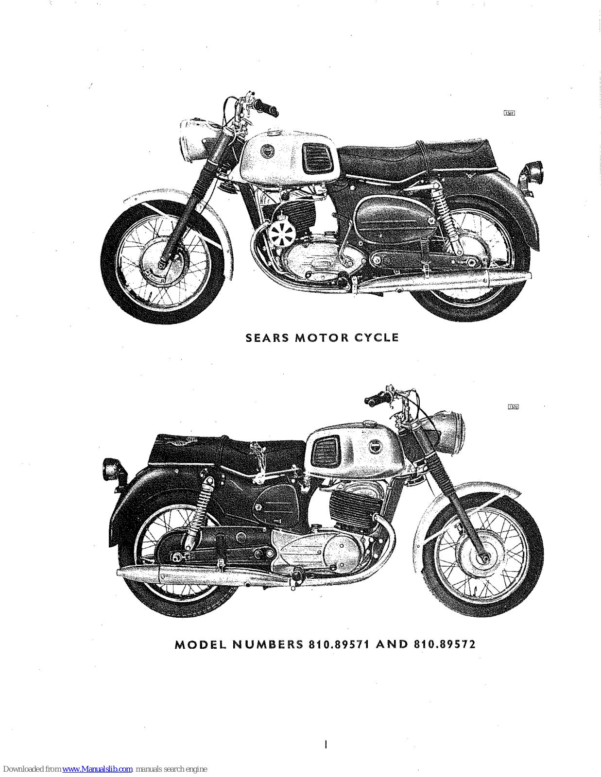


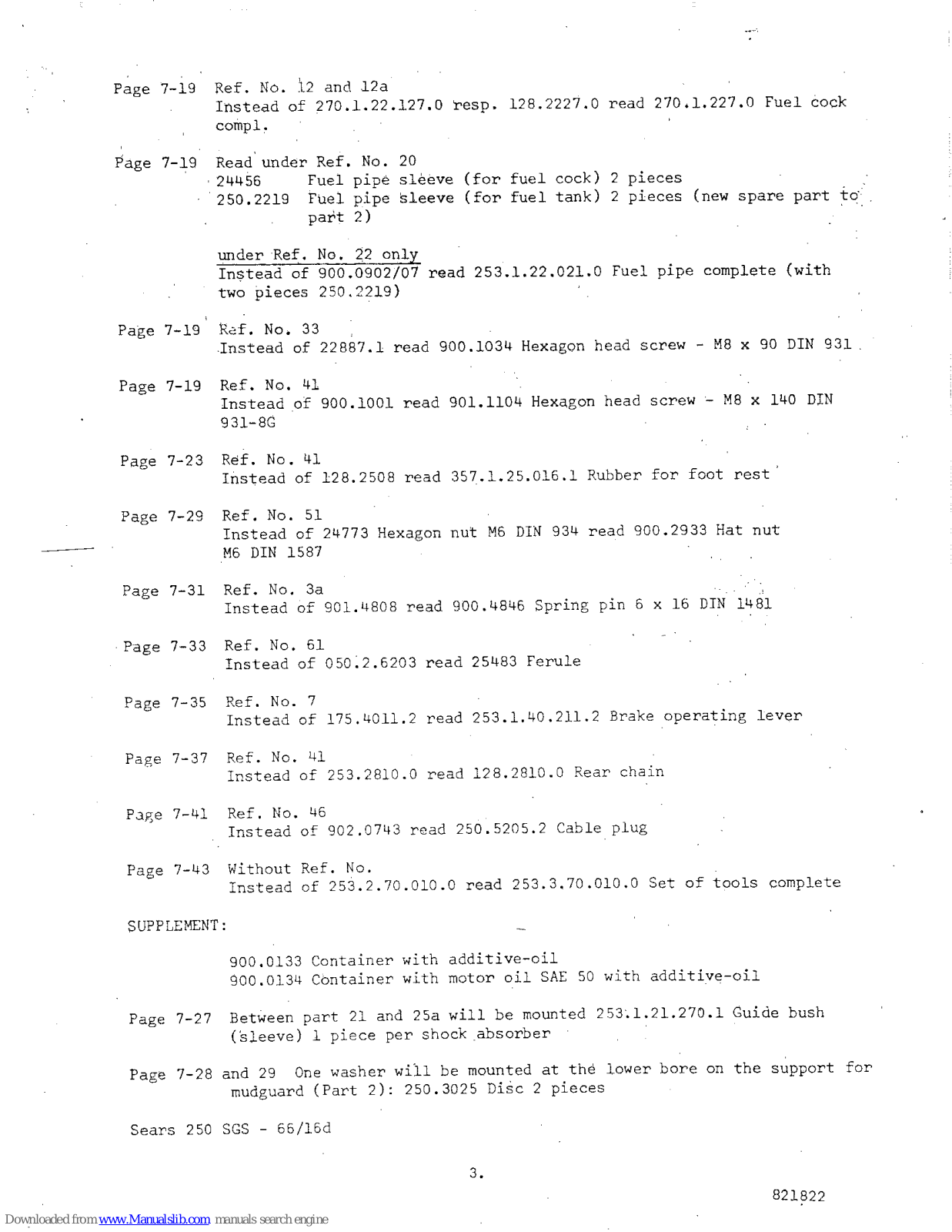

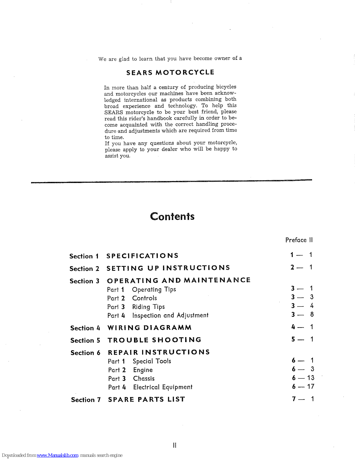
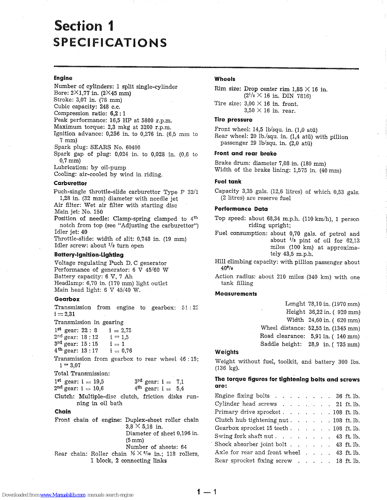
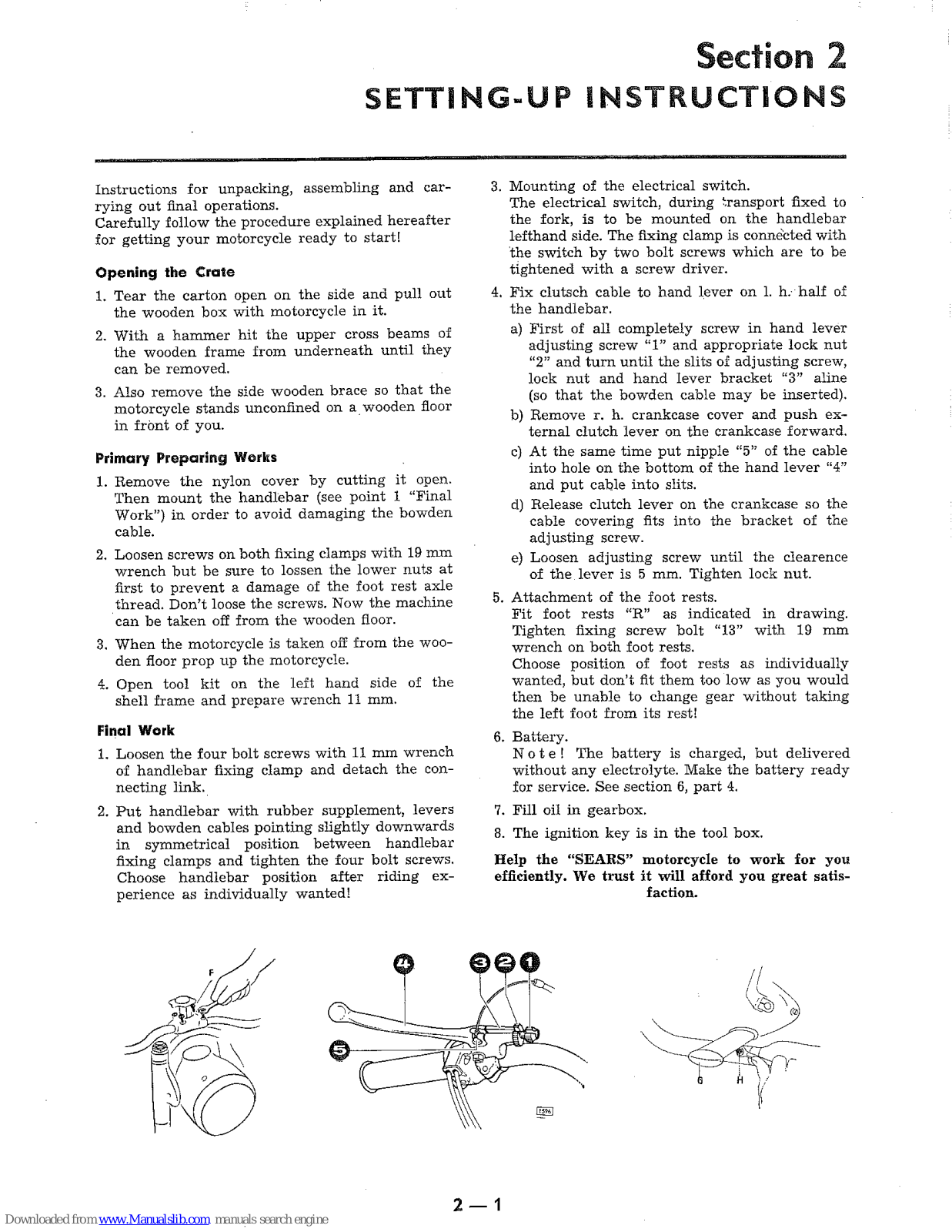

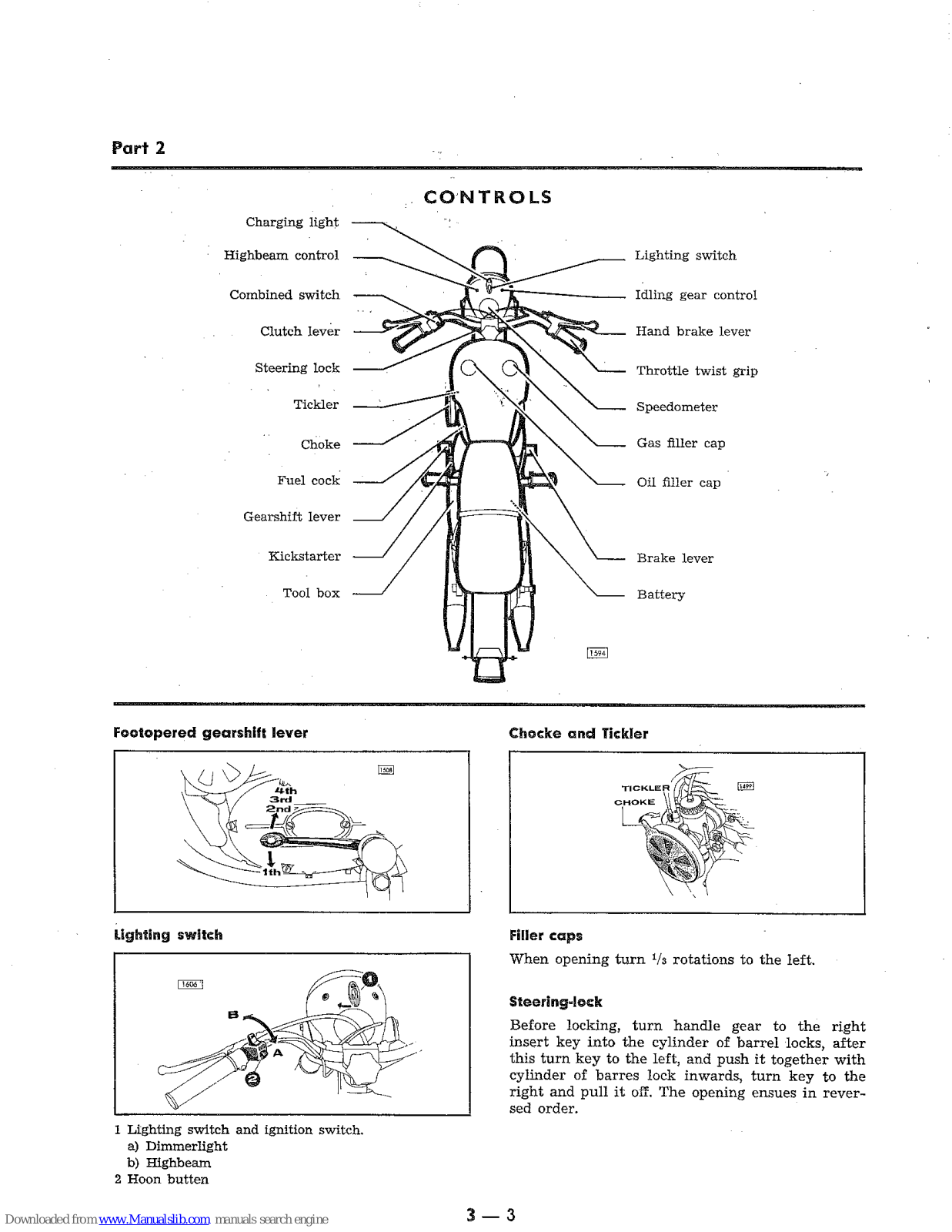
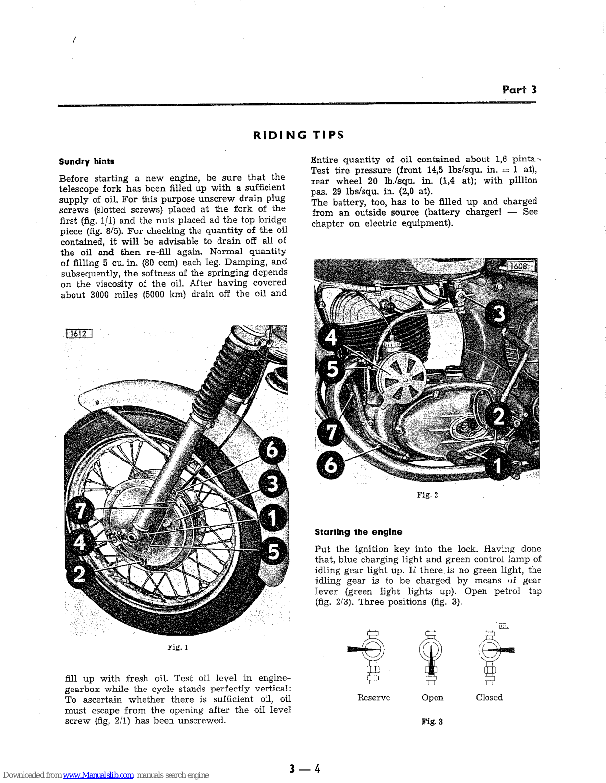
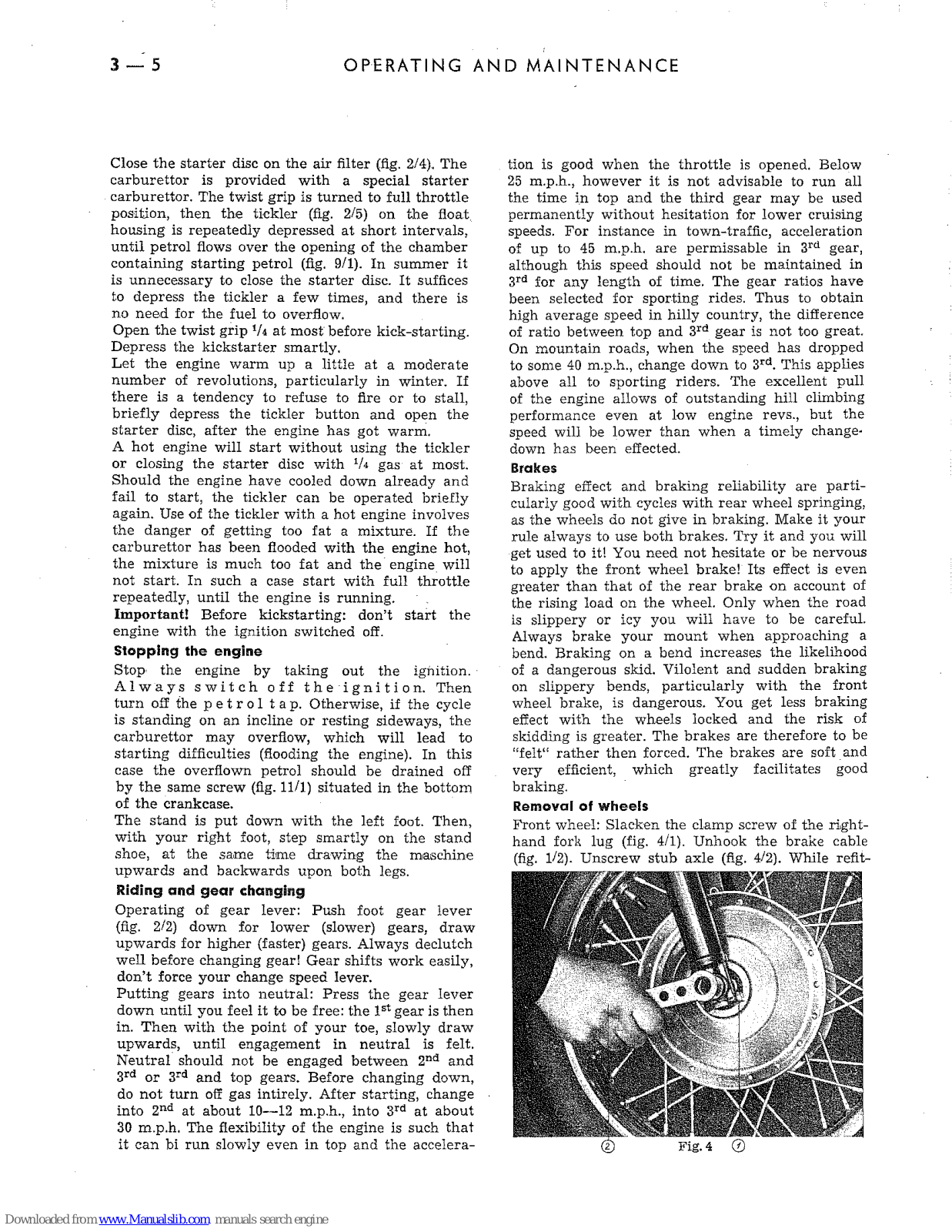
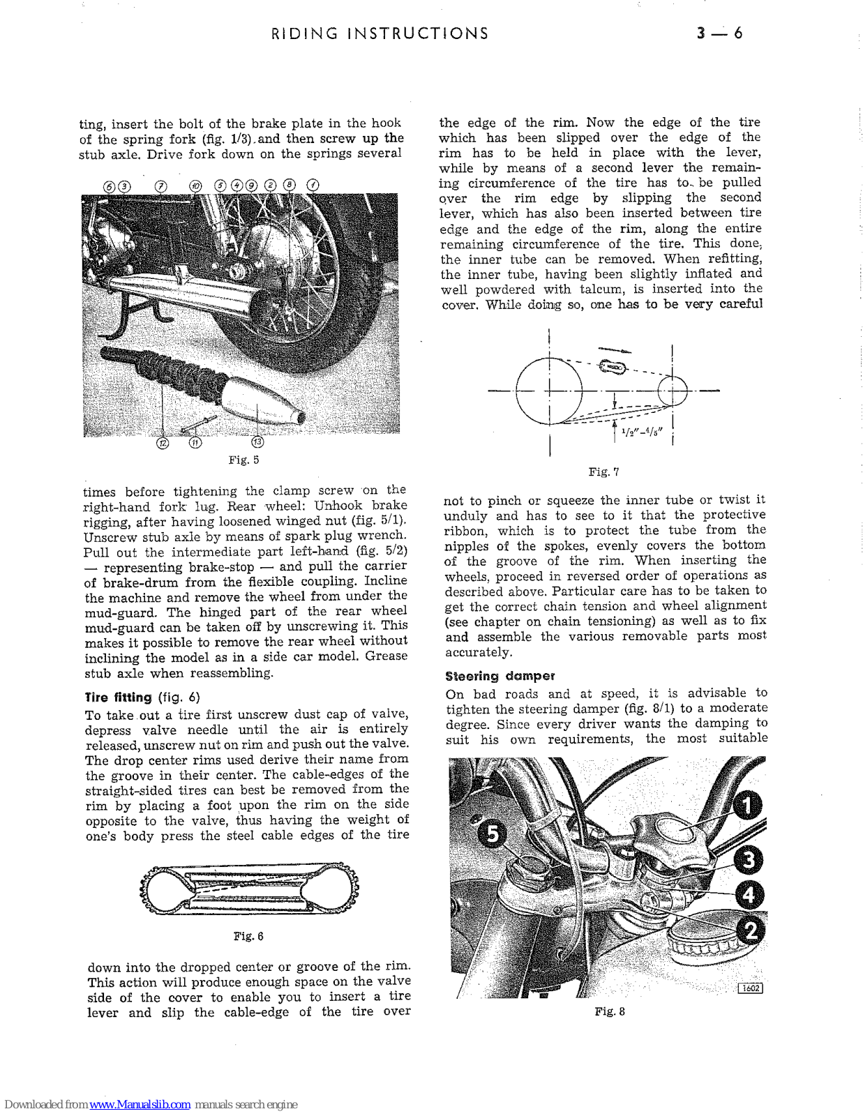
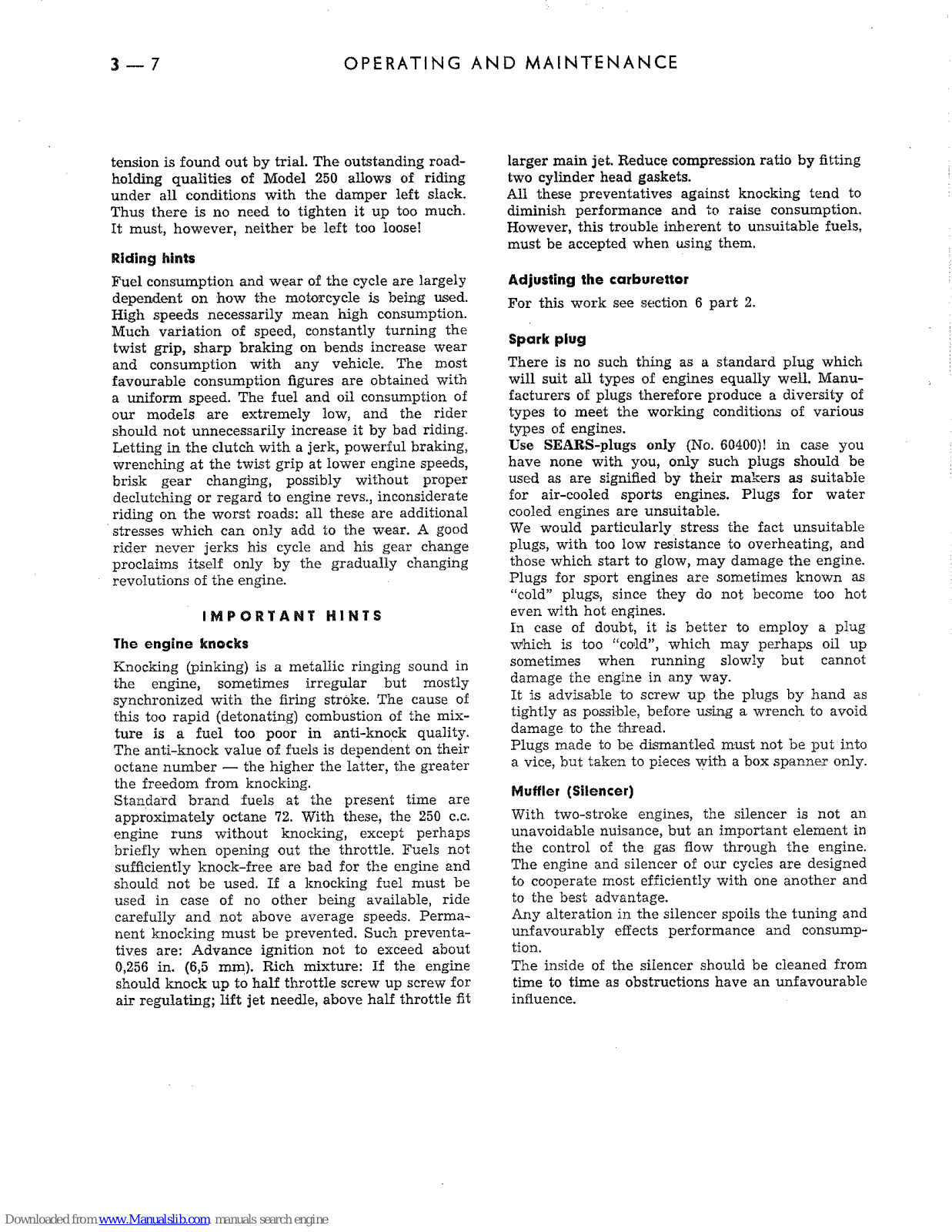
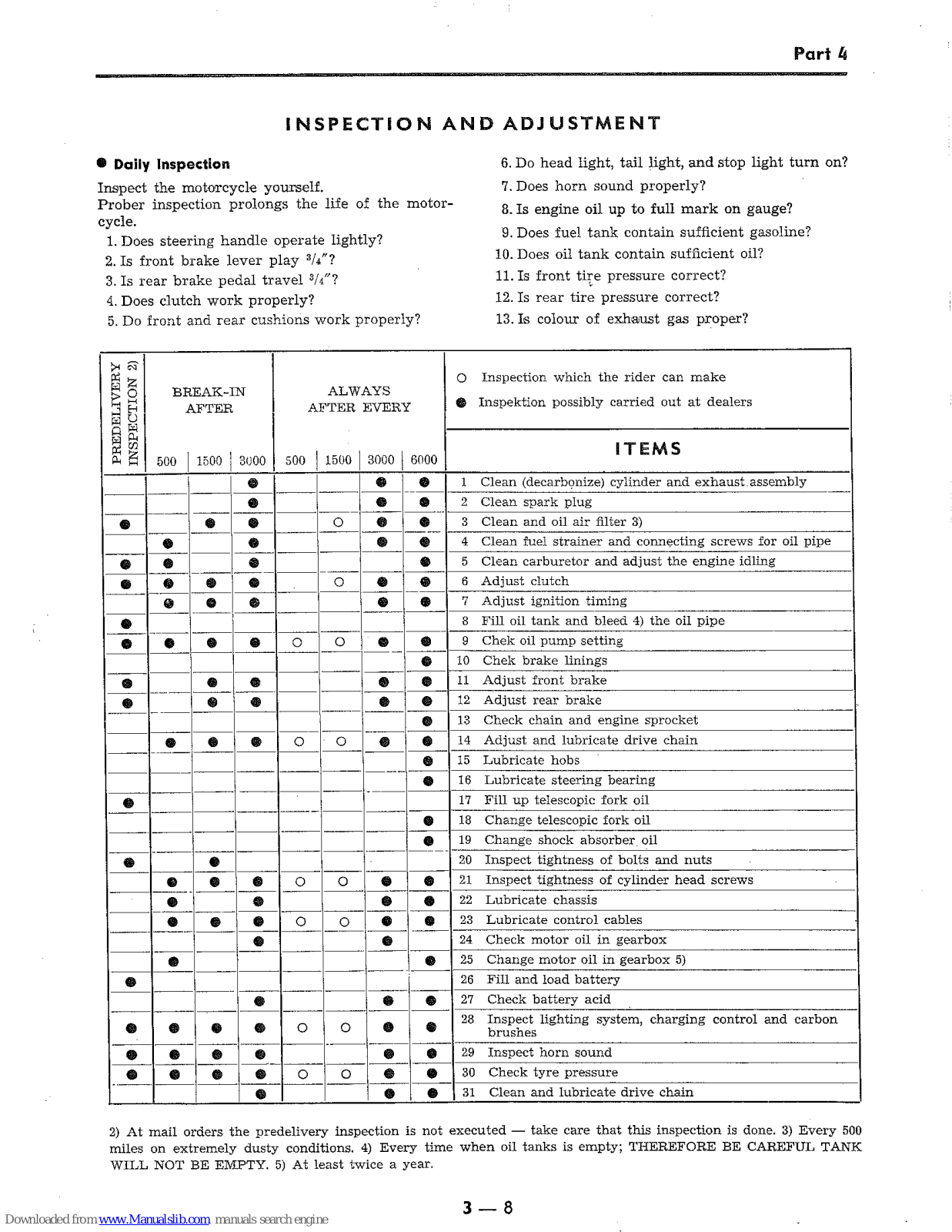
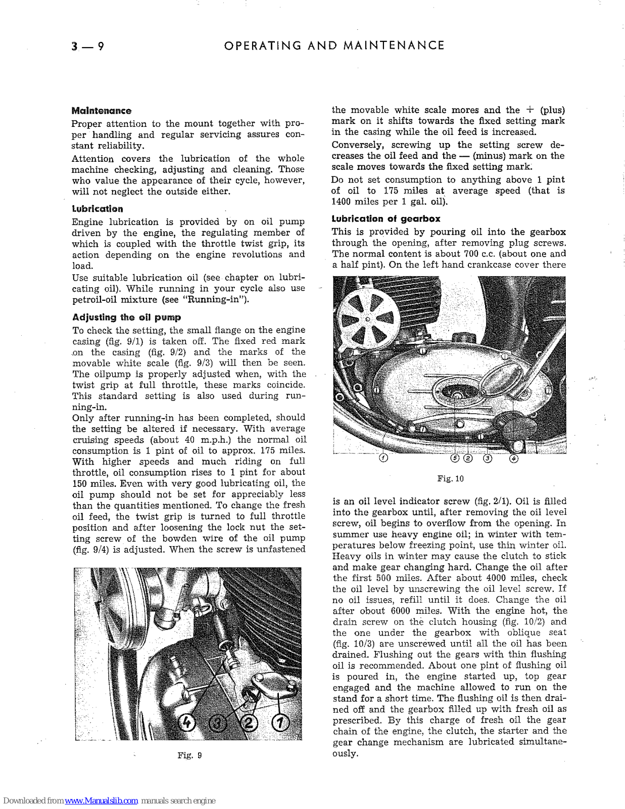
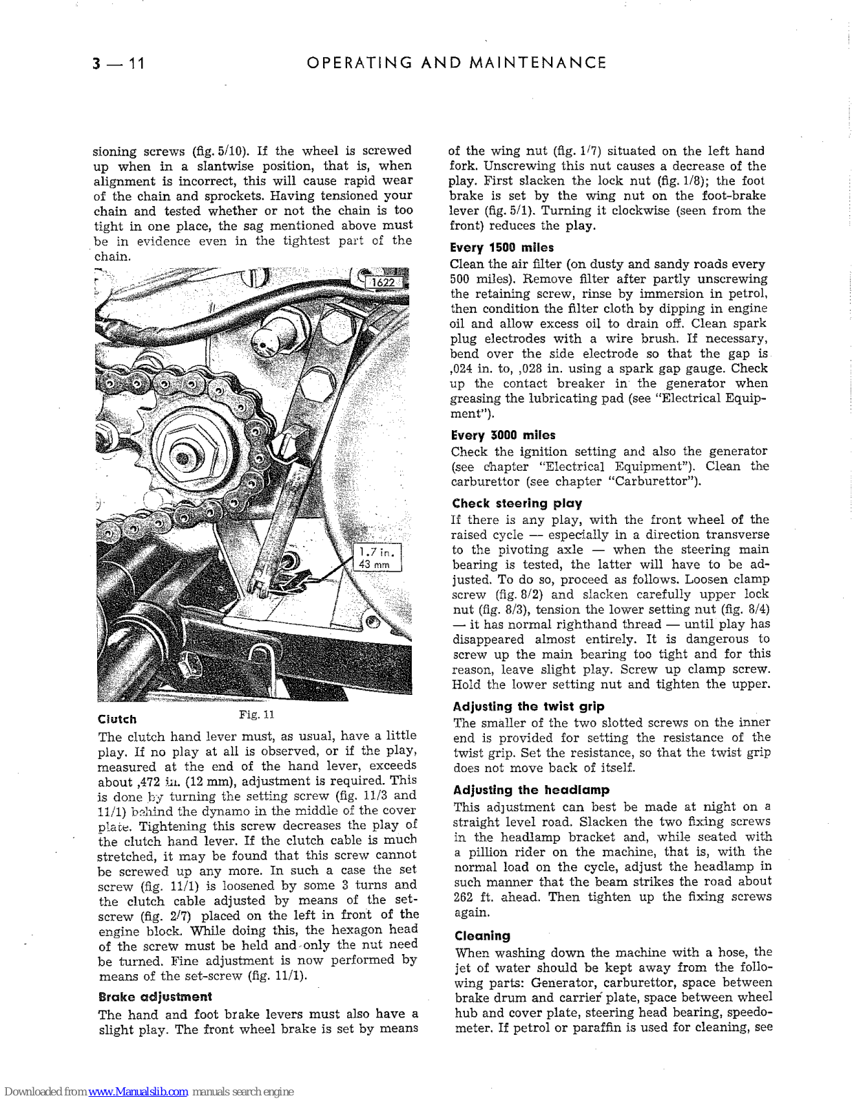
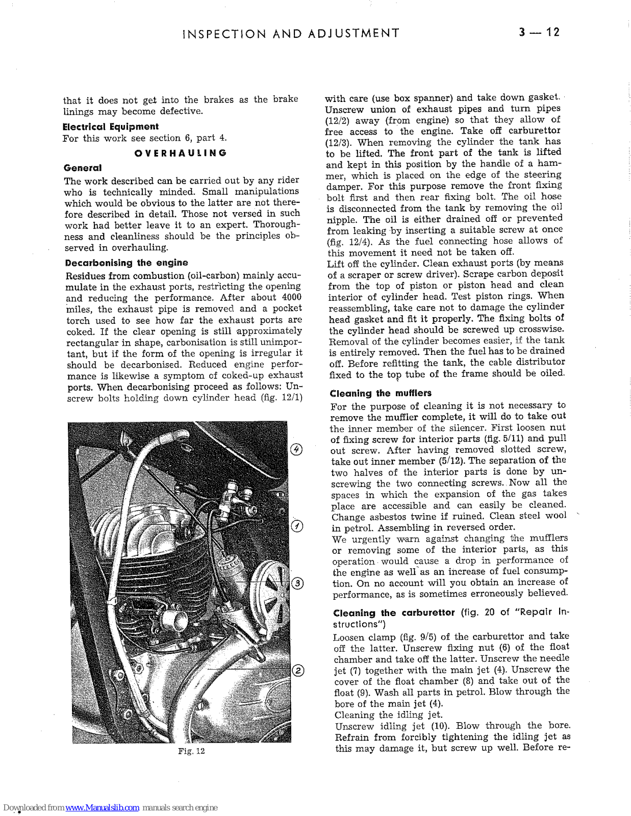
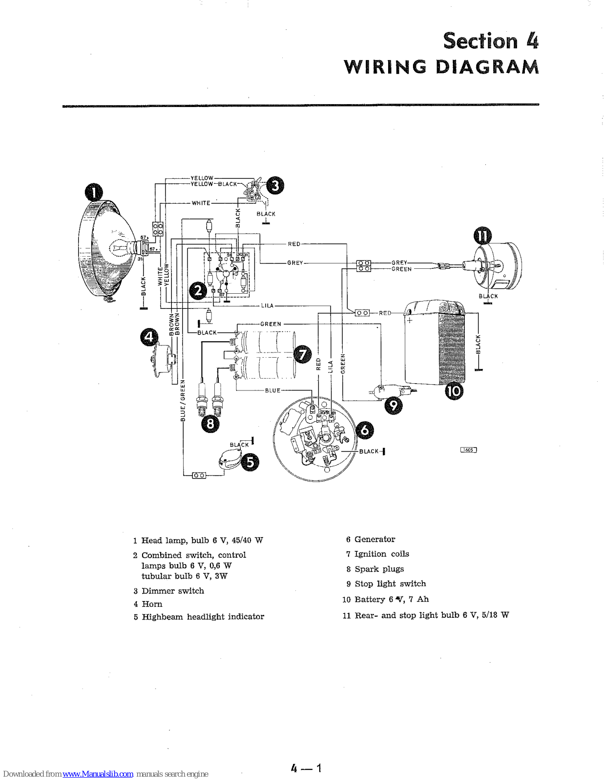
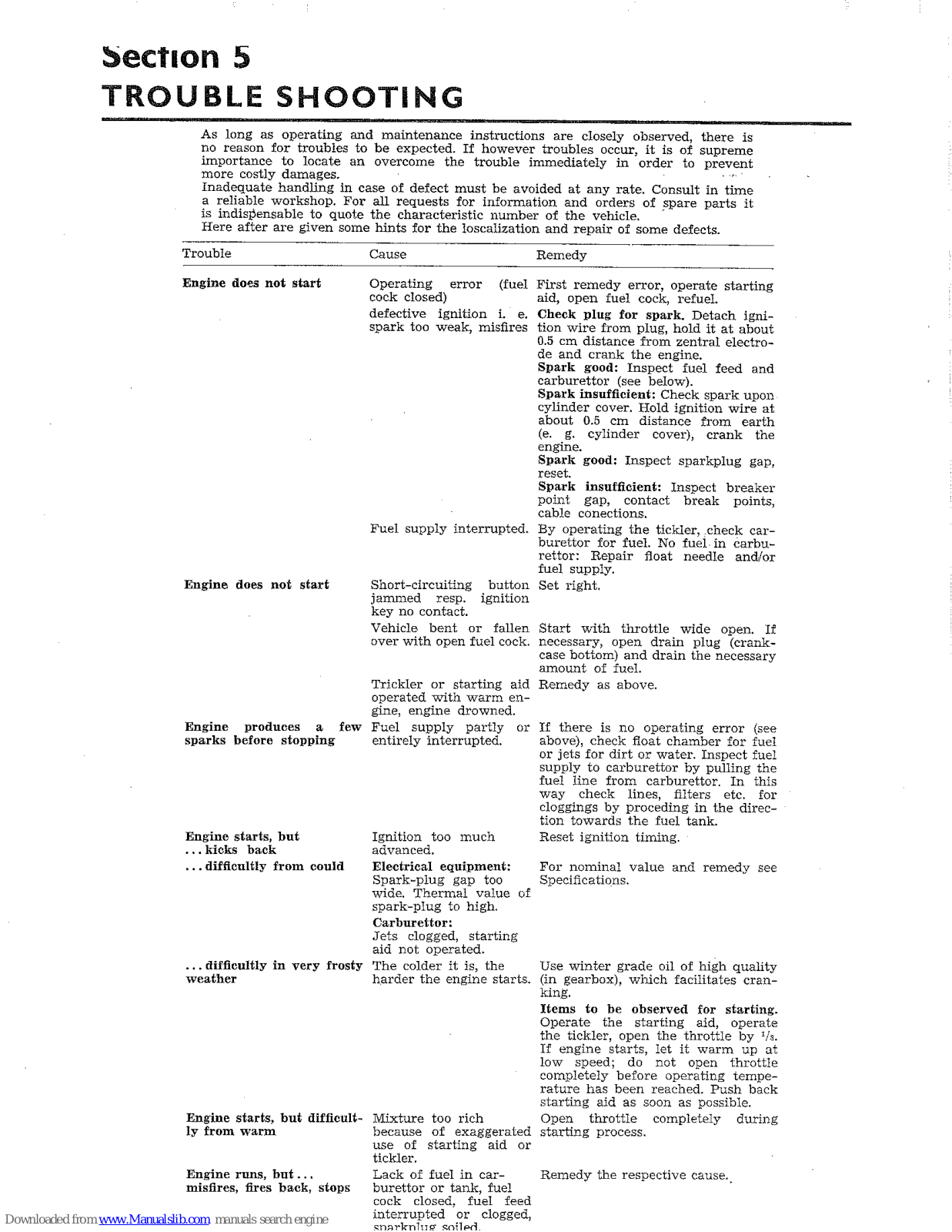
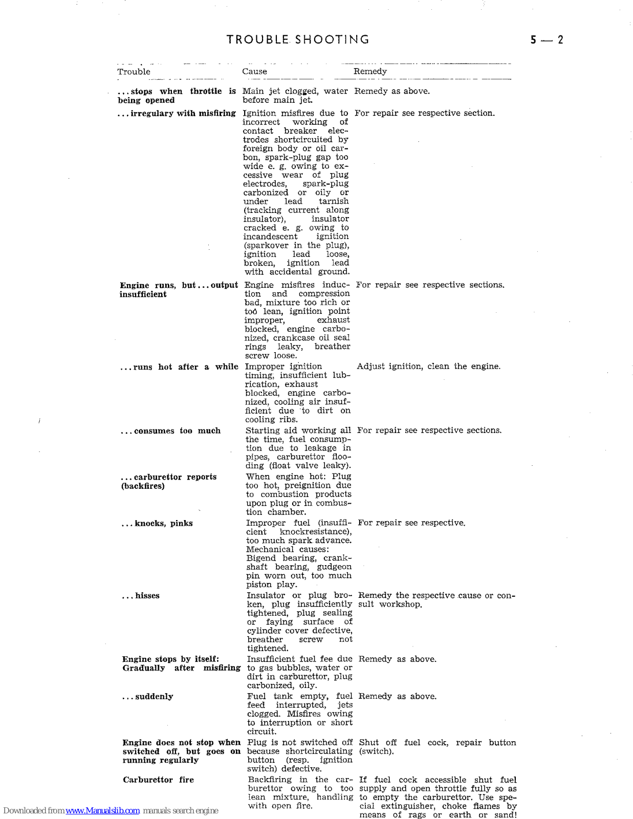
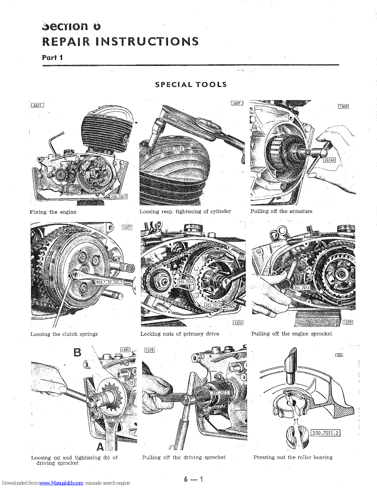
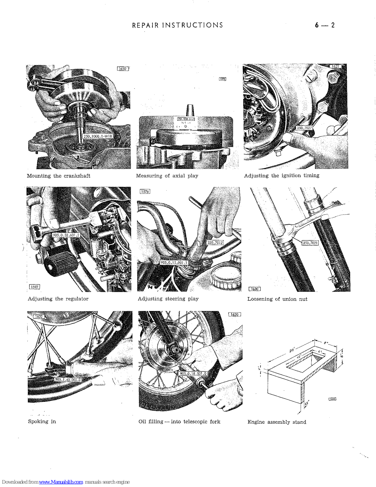


 Loading...