

Sears 788.94360 Assembly, Operating Instructions And Parts List
ASSEMBLY.
OPE'RATING
INSTRUCTIONS
AND
PARTS LIST
FOR
SEARS
MOTOR
SCOOTER
------
MODEL NUMBER
788.94360-'----_
The
Model
Number
will
be
found
on a
plate
fastened to chassis
under
the
fuel
cock.
Always
mention
the
Model
Number
in all
correspondence
regurding
the
SEARS
MOTORSCOOTER
or
when
ordering
repair parts.
,----
HOW
TO ORDER REPAIR PARTS
------,
All
parts listed herein may be
ordered
through
SEARS,
ROEBUCK
AND
CO. or SIMPSONS -
SEARS
LIMITED.
When
ordering
spare
parts
by
mail
from
the mail.
order
house
which
serves the ter-
ritory
in
which
you live, selling prices
will
be'
furnished
on
request
or
parts
will
be
shipped
at
prevailing
prices and
you
will
be
billed
accordingly.
WHEN ORDERING
REPAIR
PARTS,
ALWAYS GIVE
THE
FOLLOW-
ING
INFORMATION
AS
SHOWN IN
THIS
LIST:
1. The
PART
NUMBER.
3.
The MODEL NUMBER
788.94360
2. The
PART
NAME. 4. The
NAME
of
item-Motor
scooter.
,.----
COAST TO COAST
NATION-WIDE
-----,
SERVICE
FROM
SEARS
FOR
YOUR
SEARS
MOTOR
SCOOTER
SEARS,
ROEBUCK
AND
CO. and
SIMPSONS
-
SEARS
LIMITED in
Canada back
up
your
investment
with
quick,
expert
mechanical
service and
genuine
SEARS
re-
placement
parts.
If
and
when
you need repairs
or
service,
calion
us
to
protect
your
investment
in this fine piece
of
equipment.
f •
127A7
SEARS.
ROEBUCK
AND
CO
..
U.S.A.
IN
CANADA.
SIMPSONS
-
SEA~S
LIMITED
INTRODUCTION
This
modelofmotor
scooter
hasamodern
type
of
engine
in
which
the
distribution
is
realised
by
the
crankshaft
(rotary
valve
distribution);
furthe-
moreit'is
provided
with
a 4
speed
gear
boxinor-
der
to runinexcellent
condition
by
climbing
the
most
various
slopes
andtotake
the
greatest
pos-
sible
advantage
of
its pick -
up
qualities.
The
carburettor,
installed
on
the
crankcase,
is
in
direct
communication
with
the
pre-compres-
sion
chamber
in
corrispondence
to
the
external
diameter
of
one
of
the
crankshaft
flywheels
(see
fig.
10):
the
periphery
of
the
flywheel
rotates
very
close to
the
crankcase,
without
touching
it;
a
portioninthe
periphery
of
said
webisground
off,
and
controls
the
fuel flow to
the
pre-com-
pression
chamber,
thus
acting as a
rotary
valve.
The recess
on
the
web
periphery
has
been
shaped
in
suchaway
as to
give
the
maximum
volumetric
efficiency,
thus
obtaining
an
asymme-
trical
distribution
diagram.
It
should
be
noted
that
crankweb
and
crank-
case
are
kept
gas
tight
by
the
film
of
oil
which
rorms
between
them
and
not
by
direct
contact;
in this
way
the
system
is
not
subjec'
to
wear
by
friction, as
is
usually
the
case
with
similar
devices.
The
intake
pipeisvery
short;
itistherefore
only
the
carburettor
which
slows
down
the
flow
or
fresh
chargetothe
engine.
The
advantages
ofacorrect
reeding
system
are
therefore
clear;
more
poweratlow
revs,
and
greater
engine
elasticity. The
intake
pipe
leads
into
the
pre-compression
chamber
and
the
fresh
charge
directly
contacts
the
con. rod
big
end;
in
this
way
the
bearings
are
so efficiently
lubricated
as to
permitareductionofthe
percentage
oil con-
ten
in
the
gasoline
(2%).
The
improvement
which
the
rotary
alve
bringstothe
thermo-dynamic
performance
of
the
e
gine
can
be
appreciated
by
considering
the
at-
ness
of
the
power
'curve;
this,
asiswell
know,
renders
the
engine
capable
or
functioning
over
a
wide
rpm
range
and
of
adjusting
itsel
aU'oma-
tically,
with
slight
variation
of
speed,
'0
all
forms
or
resistance
which
the
scooter
must
ove
come
(head
wind,
gradients
etc.).
The
proverbial
climbing
ability
0'
this
motor
scooter
is
enhanced
in
this
model.
All
gradients
normally
encountered
on
main
roads
can
easily
be
climbed
in
4th
gear,
even
with
two
people
on
board;
the
most
various
slopes
can
be
climbed
at
speed
in
3rd
or
2nd
gear,
while
the
st
gear
gives
initial
acceleration
and
is
particulary
userul
on
bad
surfaces
and
side
roads.
Another
advan
age
0'
the
rotary
valveistha
eliminates
back
pressure,
i.
e.
prevents
some
of
the
fresh
fuel
from
being
pushed
back
from
he
pre-compression
chamber
towards
the
carbu-
rettor
and
wasted,
at
the
beginning
of
the
down-
wardstroke
of
the
piston.
Engine
performance
is
also
improved
by
the
use
ofaspherical
headed
piston
and
a
combu-
stion
chamber
on
the
cylinder
head
of
a special
form
to
give
to
higher
turbulence,
thus
resulting
in
higher
compression
ratio
and
thence
increase
in
both
specific
power
and
out-pu·.
In
conclusion,
for
easing
star
ing
the
carbu-
rettor
has
been
equiped
withastarter
jet
and
is
or
he
the
type
mounted
on
automobiles.
It
is
housedinthe
air
cleaner,
hasaplate-shaped
slide
valve
and
immersed
jets:
this
has
reduced
ruel
consumption
and
improved
the
general
performan-
ce
of
the
engine.
la<:ltion01Irlm.
Number
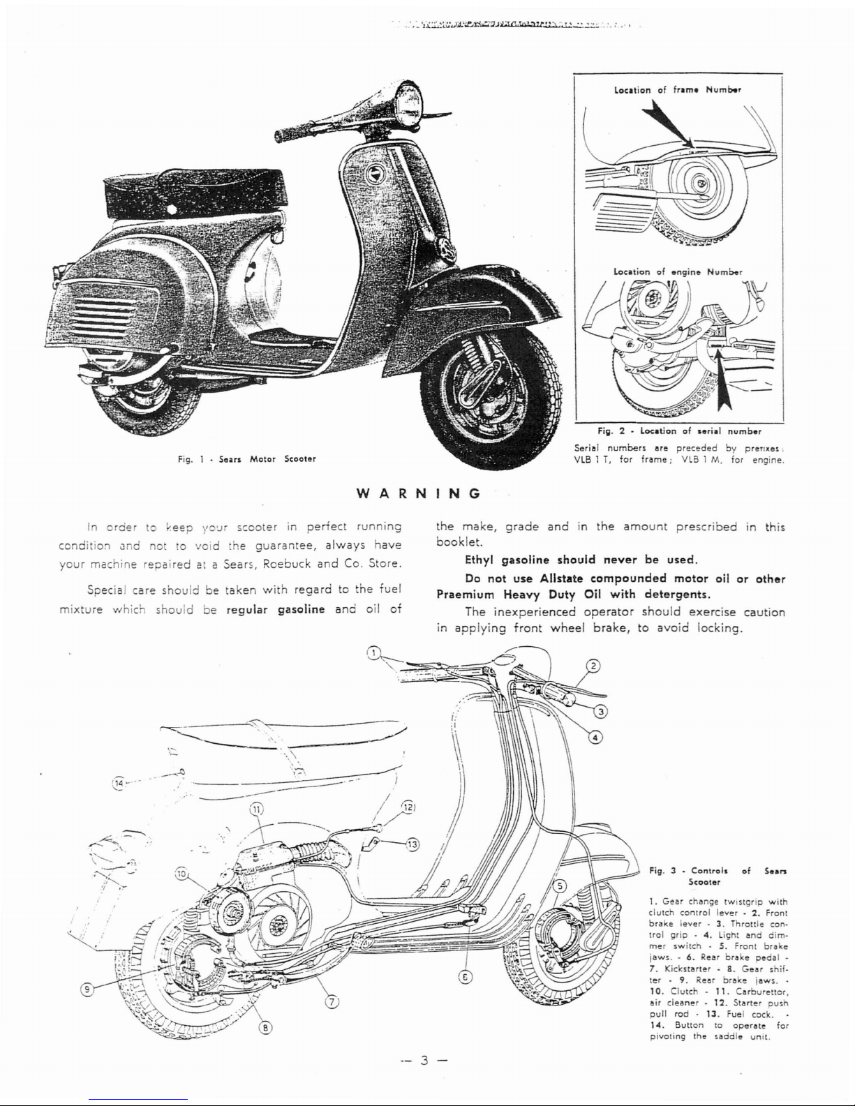
Serial
numbers
are
preceded
by
preTixas,
VlB1T,
lor
frame;
VlB
1 M, for
engine.
serial
number
Fig. 2 -
Fig. 1 . Sears Motor
Scooler
WARNING
In
order
to
~eep
I'0'.H
scooter
in
perfect
running
condition
und
no to
void
the
guarantee,
always
have
your
machine
repaired
et a
Sears,
Roebuck
and
Co.
Store.
Special
care
shouldbetaken
with
regardtothe
fuel
mixture
which
should
be
regular
gasoline
and
oil
of
the
make,
grade
and
in
the
amount
prescribed
in this
booklet.
Ethyl
gasoline
should
never
be
used.
Do
not
use
Allstate
compounded
motor
oil
or
other
Praemium
Heavy
Duty Oil
with
detergents.
The
inexperienced
operator
should
exercise
caution
in
applying
front
wheel
brake,
to
avoid
locking.
1. Gear chllnge
tWtStgrip
with
clutch
control
lever·2.Front
brake
lever.3.
Throttle con·
trol
grip.4.
Light
and
dim-
mer
switch~5.
Front
br~ke
jaws.-6.
Rear
breepedal
-
7.
Kickstarter -8.Geer
shil.
ter-9.
Reer
brake
iaws
..
10.
Clute -
11.
Carburettor,
air
cleaner·
12.
Starter
push
pull
rod·
13.
Fuel cock.
14.
Button
to
operate
for
pivoting
the
saddle
unit.
Fig. 3 -
Control.
ofS••
n
Scooter
I:
~
.1
~
....--:
\)
j
I
l
I
t12)
//
-")
I,
---~.~--------
~
..
,.
\.:..
_
.....
\
--
3 -
---------
//
(
.
__
,21
--
------.~
......
,\
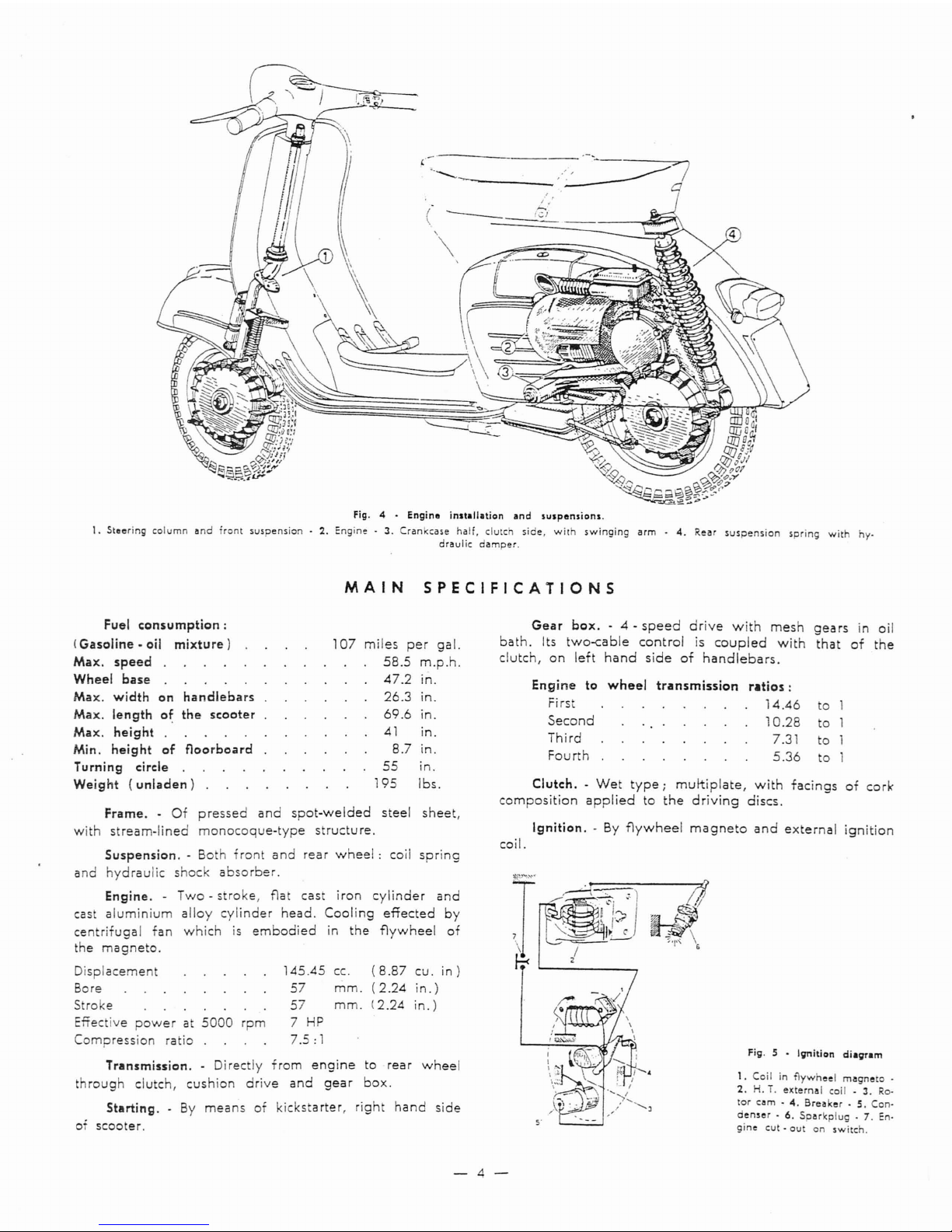
Fig. 4 •
Engine
inst.lI.tion
and
sUlpensionl.
1.
Steering
column
and
front
suspension·
2.
Engine
3.
Crankcase
half,
clutch
side,
wit
swinging
arm.4.
Rear
suspension
spring
with
hy.
draulic
damper.
MAIN
SPECIFICATIONS
Transmission.
Directly
from
engine
to
rear
wheel
through
clutch,
cushion
drive
and
gear
box.
Starting.-By
means
of
kickstarter,
right
hand
side
of
scooter.
Fuel
consumption:
(Gasoline.
oil
mixture)
107
miles
per
gal.
Max.
speed
58.5
m.p.h.
Wheel
base
47.2
in.
Max.
width
on
handlebars
26.3
in.
Max.
length
of
the
scooter
69.6
in.
Max.
height
41
in.
Min.
height
of
floorboard
8.7
in.
Turning
circ:le
55
in.
Weight
(unladen)
195
Ibs.
to
to
to
to
1.
Coil in
flywheel
magneto
_
2.
H.i.externat
coil -3.Ro.
tor
cam·4.Breaker.S.Con-
den.er•6.
Sparkplug.7.
En.
gine
cut·
outanswitch.
Fig. 5 •
Ignition
diagram
transmission
ratios:
14.46
10.28
7.31
5.36
J
;'1"
\
5"
Engine
to
wheel
Fi
rst
Second
Third
Fourth
J
t;<
coil.
Clutch.-Wet
type;
multi
plate,
with
facings
of
cork
composition
applied
to
the
driving
discs.
Ignition.-By
flywheel
magneto
and
external
ignition
Gear
box.
- 4 -
speed
drive
with
mesh
gears
in
oil
bath.
Its
two-cable
control
is
coupled
with
that
of
the
clutch,
on
left
hand
side
of
handlebars.
cc.
(8.87
cu.
in)
mm.
(2.24
in.)
mm.
(2.24
in.)
145.45
57
57
7
HP
7.5:
1
Frame..Of
pressed
and
spot-welded
steel
sheet,
with
stream-lined
monocoque-type
structu
re.
Suspension.
- Both
front
and
rear
wheel:
coil
spring
and
hydraulic
shock
absorber.
Engine.-Two-stroke,
flat
cast
iron
cylinder
and
cast
aluminium
alloy
cylinder
head.
Cooling
effected
by
centrifugal
fan
which
is
embodied
in
the
flywheel
of
the
magneto.
Displacement
Bore
Stroke
Effective
powerat5000
rpm
Compression
ratio
-4-
Lubrication. -Bythe
oil in
rue
I
ixture
for
pis
'on,
cylinder,
wrist
pi
,co.
rod,
crankshaft,
main
bea-
rings. Bot clu c
and
gear
box
o
",ateinoil
bat
Carburettor.-With
float-cham-
ber
(see
fig.11);
air
cleaner
moun-
tedonthe
engine.
Air
goestothe
carburettor
through
a
large
inlet
tube
andasilencing
chamber
with
~"ter.
Model0carburettor:
DeWOr-
to
SI
20/i7
D -
Ven
uri
17
mm.
(
".67)
- Main jet
102/100
(0".
04
) - Idler jet
42/100
(0".0163)
- Air-vent for
main
jet
160/100
(0"
.063)-Mixer
type
E 1. - Air
ventoidler
jet
160/100
(0"
.063)
.
Spray
nozzle
200/100
(0"
.07B8)
-
Starter
jet
60/100
(0".0236)
Floa
chamber
fuel
level
20.5
mm.
(0."807==0."039).
Feeding.
- Fuel
feed
to
he
carburettor
is
provided
for
by
gravi'y
(see
fig.
1)
with
gasoline
- oil
mixture.
Fuel
tank.
- Total
capacity:
2,03
gals.;
Reserve:
VI
,'3
gal.;
Three-way
cock:«open»
- «
closed»
- «
reserve
».
Muffier. -
Expansion
and
absorption
combined
type.
Handlebars.-Pressure
die
cas
in
ligh
alloy
and
desig
ed
so as 0
house
both
trapezoidal
shaped
head-
lamp
a d
~peedo
eter.
All
he
con
rei
cables
and
elec-
trical
wires
to
is
group
are
concealed
herein.
(See
Tlg.
3).
Steering
column.-The
steering
column
bears
the
ha
dlbears,
clamped
on
its
top
end,
and
the
front
wheel
swinging
hub,
pivoted
at its
bottom
end
throughastub
axle.
Lighting
and
horn..By
flywheel
magneto,
feeding
bot
ead
lamp(wo-bea
), tail
lamp,
horn
and
stop
light
(see
fig.
9).
Brakes. -
Expanding
type.
Font
brake:
co
trol
lever
on
right
hand
side
of
a
dlebars.
REar
brake:
con
rol
pedal
on
right
hand
side
of
floo
board.
The
rear
brake
jaws
are
hinged
on
indepen-
detpivots.
Wheels.-Of
pressed
steel
sheet,
interchangeable
and
easily
removable,
since
they
are
assembled
in
an
auto-
mobile
- like
system.
Tires:
dia.
3.5x10
in.
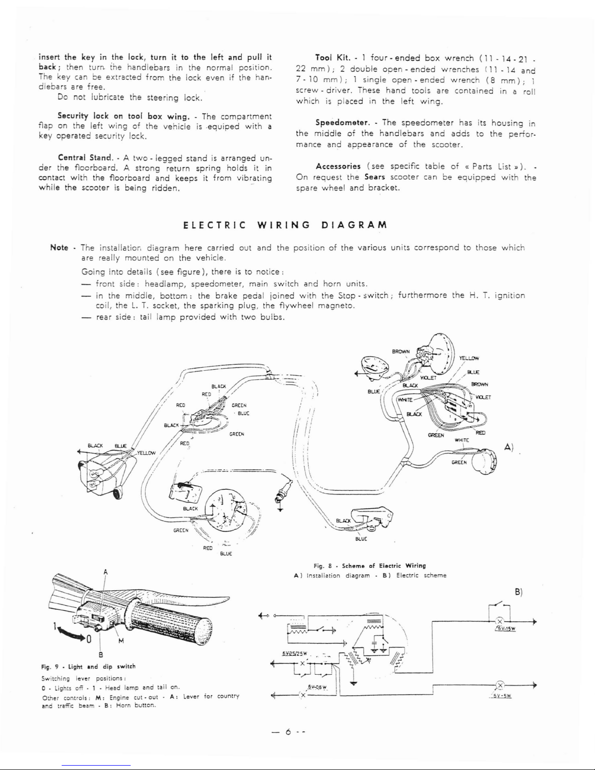
Steering
Lock. - A
suitable
security
lockisarranged
o e fra e, nEa
the
handlebars.
Turn
the
handlebars
to
e left,
then
rotate
the
key
and
push
inwards,
so
tha
i' t rusts
the
sliding
bar
against
the
steering
column.
To
ease
the
insertion
of
t e
sliding
bar
into
the
hole
0'
t e
steering
column,
slightly
turn
the
handlebars.
from
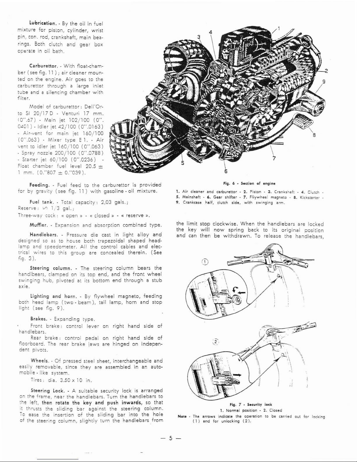
Fill. 6 -
Sectionofengine
1. Air
cleaner
and
carburettor-2.
Piston -3.Crankshaft.4.
Clutch
S.
Mainshaft-6.
Gear
shifter-7.
Fliywheel
magneto.8.
Kickstart~r
9.
Crankcase
half,
clutch
side,
with
swinging
arm.
the
limit
stop
clockwise.
When
the
handlebars
are
locked
the
key
will
now
spring
back
to
its
original
posi
ion
and
can
then
be
withdrawn.
To
release
the
handlebars,
Fill. 7 -
Security
lock
1.
Normal
position-2.
Closed
Note
. The
arrows
indicate
the
operationtobe
carried
out
for
locking
(
1)
and
for
unlocking
(2).
-5-
insert
the
keyinthe
lock,
turn
it to
the
left
and
pull
it
back i
then
turn. the
handlebars
in
the
normal position.
The key
canbeex
racted
from
the
lock
evenifthe han-
dlebars
are
free.
Do
no lubricate
the
steering
lock.
Security lock on tool
box
wing.
- The
compartment
flap
on
the
left
wingofthe
vehicleis.equiped
with
a
key
operated
security lock.
Central
Stand.
- A
two-legged
standisarra
nged
un-
der
the
floorboard.
A
strong
return
spring
holdsitin
contact
with
the
floorboard
and
keepsitfrom
vibrating
while
the
scooterisbeing
ridden.
-
Tool
KiL-1
four-ended
box
wrench(1-14-21-
22
mm);
2
double
open-ended
wrenches
(11 - 14
and
7·
10
mm);
1
single
open·
ended
wrench
(8
mm);
1
screw-driver.
These
hand
tools
are
contained
in a roll
whichisplaced
in
the
left
wing.
Speedometer.
- The
speedometer
has
its
housing
in
the
middle
of
the
handlebars
and
adds
to
the
perfor.
mance
and
appearance
of
the
scooter.
Accessories
(see
specific
table
of«Parts
ist
»).
-
On
request
the
Sears
scooter
can
be
equipped
with
the
spare
wheel
and
bracket.
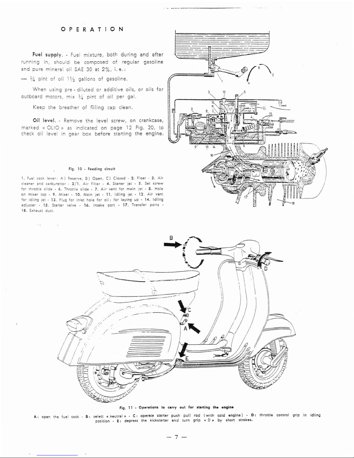
ELECTRIC
WIRING
DIAGRAM
Note·
he installatior,
diagram
here
carried
out
and
the
positionofthe
various
units
correspond
to
those
which
are
really
mounted
on
the
vehicle.
Going
in0details
(see
figure),
thereisto
notice:
fron
side:
headlamp,
speedometer,
main
switch
and
horn
units.
in
the
middle,
bottom:
the
brake
pedal
joined
with
the
Stop·
switch;
furthermore
the
H.T.ignition
coil,
thel.T.
socket,
the
sparking
plug,
the
flywheel
magneto.
rear
side:
tail
lamp
provided
with
two
bulbs.
A)
REO
eu)€
Fill. 9 • ligftt
Ind
dip
switch
Switching
I~ver
positions:
o .
lightson- 1 -
Heed
lamp
and
tail
on.
Other
controls:
M:
Enoine
cut·
out-A:
lever
for
country
end
traffic
beam•B:
Horn
button.
Fig_
8 •
SchemeofElectric
Wiring
A)
Installation
diagram-B)
Electric
scheme
B)
+-0
.,.,
--.-.-......,.'
r------~=..,
r----------:2·---·~
'-------------'
.:u:.s.w.
- 6
--
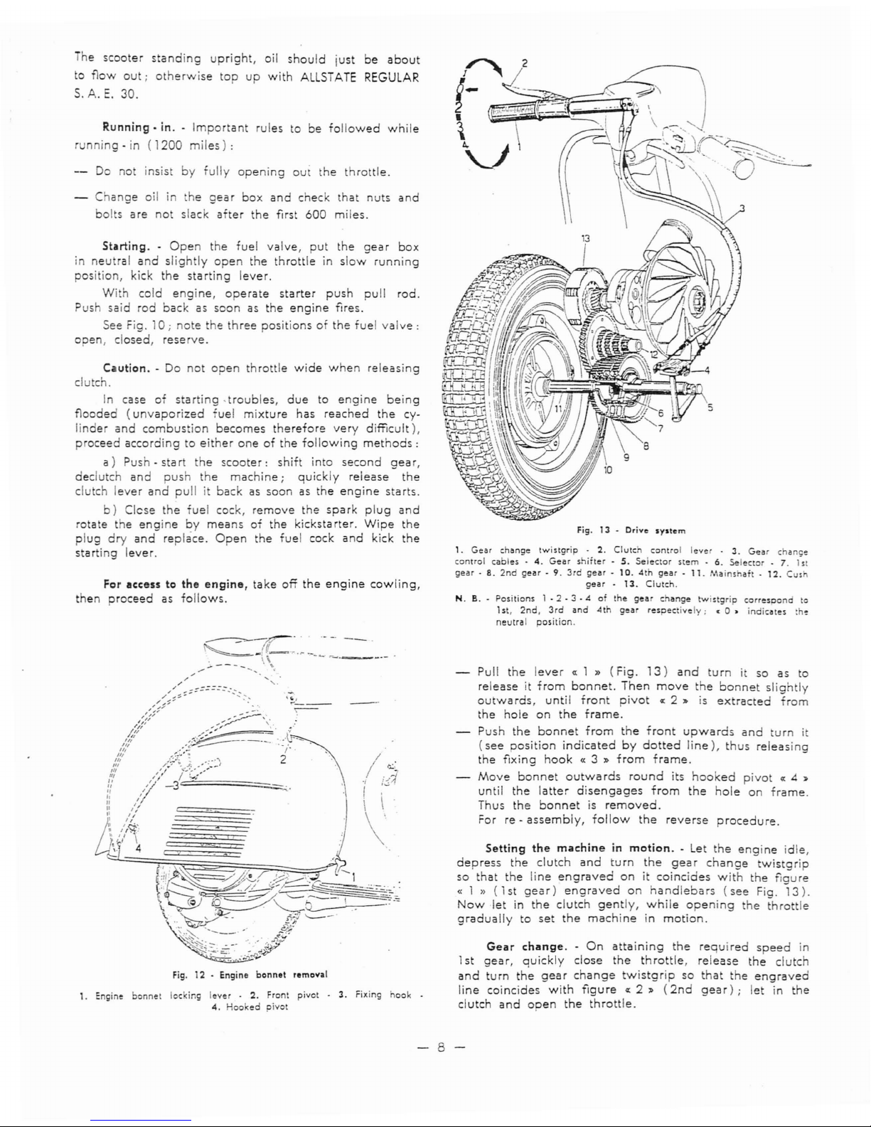
OPERATION
Fuel
supply..Fuel
mixture,
both
during
and
after
r n
ing
in,
should
be
composed
of
regular
gasoline
and
pure
mineral
oil
SAE
30 at
2%,
i.
e.:
%
pintofoil
1
1
,.2
gallonsofgasoline.
When
using
pre·
dilutedoradditive
oils,oroils
for
o
board
mo
ors,
mix
%
pint
of
oil
per
gal.
Keep
the
brea
her
OT
filling
cap clean.
Oil
level.
. Remove the
level
screw,
on
crankcase,
mar.
ed«OLIO»
as
indicated
on
page
12 Fig. 20,
to
chec o'il
levelingear
box
before
starting
the
engine.
Fig.10.
Feeding
circuit
1.
Fu~1
cock
lever:A)<eserve,
B)
Open,C)Closed·2.Float·3.Air
c1eane
and
carburenor.3/1.
Air
'ilter-4.
Stoner
iet - 5. Set
screw
'or
thronle
slide·6.Throltle
slide-7.
Air
ven
for moin iel .8.Hole
on
mixer
top'9.Mixer·
10.
Main
iet -
11.
Idling iet .
12.
Air
vent
for
idling iet .
13.
Plug
ior
inlet
hole
for
oil:
ror
layingup-
14.
Idling
odj Sler -
15.
Stoner
valve -
16.
Intake
port·
17.
Transfer
ports·
1
a.
Exhaust duct.
.....
~-..-
OW
------
.-
3-
-'
-'
.----=-_~!
B
•
Fig. 11 •
Operotionltocarry
out
for
starting
the
."Vin.
A:
open
the
fuel
cock _B:select<neutrol•.C:
ope
rote
storter
push
pull
rod
(with
cold
engine)•D:
throttle
control
grip In
idling
position.E:
depre..the
kickstorter
ond
turn
grip
<
D.
by
short
stroke
•.
-7-
he
scooter
standing
upright,
oil
should
just
be
about
to
flow
out;
otherwise
top
up
with
ALLSTATE
REGULAR
S.A.E.
30.
Running.
in. -
Important
rulestobe
followed
while
running-in
(1200
miles):
Do
not insist
by
fully
opening
out
the
throttle.
Change
oil in
the
gear
box
and
check
that
nuts
and
bolts
are
not
slack
after
the
first
600
miles.
Starting.-Open
the
fuel
valve,
put
the
gear
box
in
neutral
and
slightly
open
the
throttleinslow
running
posi ion, kick
the
starting
lever.
With
cold
engine,
operate
starter
push
pull
rod.
Push
said
rod
backassoonasthe
engine
fires.
See
Fig.
10;
note
the
three
positionsofthe
fuel
valve:
open,
closed,
reserve.
Caution.
- Do
not
open
throttle
wide
when
releasing
clutch.
In
case
of
starting
.troubles,
due
to
engine
being
flooded
(unvaporized
fuel
mixture
has
reached
the
cy-
linder
and
combustion
becomes
therefore
very
difficult),
proceed
accordingtoeither
oneofthe
following
methods:
a)
Push-start
the
scooter:
shift
into
second
gear,
declutch
and
push
the
machine;
quickly
release
the
clutch
lever
and
pullitbackassoonasthe
engine
starts.
b)
Clese
the
'uel
cock,
remove
the
spark
plug
and
rotate
the
engine
by
means
of
the
kickstarter.
Wipe
the
plug
dry
and
replace.
Open
the
fuel
cock
and
kick
the
starting
lever.
For
ac:c:esstothe
engine,
take
ofT
the
engine
cowling,
then
proceed
as
follows.
.~~--
Fig.
12 • Engine
bonnet
removal
1. Engine
bonnet
locking
lever.2.
Front pivot .3.Fixing hook .
4.
Hooked
pivot
Fig.13.
Drive
system
1.
Gear
change
twistgrip.2.
Clutch
control
lever .3.Ge..change
control
cables-4.
Gear
shifter
-S.Selector
stem-6.
Selector.
7. 1st
gear
- 8.
2nd
gear-9.
3rdge..-10.
4th
gear·
11.
Mainshal.12.
Cush
gear-13.
Clutch.
N. B. - Positions
1·2
- 3
.401the
gear
change
twistgrip
corresoond
to
1st.
2nd,
3rd
and
4th
gear
respec
ively;•0»
indicates
,he
neutral
position.
Pull
the
levera:1 »
(Fig.
13)
and
turnitso
as
to
releaseitfrom
bonnet.
Then
move
the
bonnet
slightly
outwards,
until
front
pivota:2"
is
extracted
from
the
hole
on
the
frame.
Push
the
bonnet
from
the
front
upwards
and
turn
it
(see
position
indicated
by
dotted
line),
thus
releasing
the
fixing
hook
« 3 "
from
frame.
Move
bonnet
outwards
round
its
hooked
pivota:4 "
until
the
latter
disengages
from
the
hole
on
frame.
Thus
the
bonnet
is
removed.
For re -
assembly,
follow
the
reverse
procedure.
Setting
the
machineinmotion.
- Let
the
engine
idle,
depress
the
clutch
and
turn
the
gear
change
twistgrip
so
that
the
line
engraved
onicoincides
with
the
fiaure
«
1»
(1st
gear)
engraved
on
handlebars
(see
Fig.
13).
Now
let in
the
clutch
gently,
while
opening
the
throttle
gradually
to
set
the
machine
in
motion.
Gear
change.-On
attaining
the
required
speed
in
1st
gear,
quickly
close
the
throttle,
release
the
clutch
and
turn
the
gear
change
twistgrip
so
that
the
engraved
line
coincides
with
figurea:2"
(2nd
gear);
let in
the
clutch
and
open
the
throttle.
-8-
Repeat his
procedure
for
changing
into
3rd
and
4th
gear
and
for
changing
down.
See
he
dr:'/e
$ystem
on
Fig. 13.
hen
you
reduce
he
speedofyour
machine,
change
down
withou
elary'o
avoid
irregular
engine
running
and
stallinga'low
revs.
Do
no
turn
the
gear
change
wistgrip
while
the
e
gineisno
running.
As
soon
as
gear
change
troubles
arise,
particularly
w e
he
con rol
becomes
ha rd,
customers
should
have
eir
machines
adjusted
byaSears
Store.
Slow
running
adjustment.
- 0
hand
toolisreauir-
ed
'or
his
job.
Idling revs
can
be
raised
or
red~ced
respectively
by
simply
tightening
or
slac
ening
the
knurled
slot
ed
screw
on air
cleaner
steel
sheet
cover
(No.5,
Fig.
0).
This
screw
controls
the
throttle
slide
valve.
The
adjuster
screw
for
the
throttre
control
cable
is
installed
on
the
air
cleaner
case.
This
screw
is
to
be
reset
only
when
necessary
and
while
dismantling
and
e -
assembling.
Opposite
to
said
adjuster
screw
there
is
on
the
air
cleaner
caseaplugged
hole
for
access
to
~--=--v
. . / .
i'~-/'
I
Fig.14.
Dismantling
the
front
wheel.
a
ohe
screw
(sprigloaded);
see
Fig.
10
No.
14.
This
screw
controls
the
flow
of
carburated
air
through
he
duc
from
the
idling
jet,
and
consequently
the
idling
evs.
We
recommend
that
customers
refrain
from
re-
setti g this
screw
unless
absolutely
necessary
or
during
dismantling
and
re -
assembling
operations
that
should,
anyway,
be
entrusted
to a
Sears
Store.
Stopping
the
engine.-Push
the
earthing
button.
This will
leave
the
cylinder
fulloffuel
vapours,
and
the
next start
will
be
much
easier.
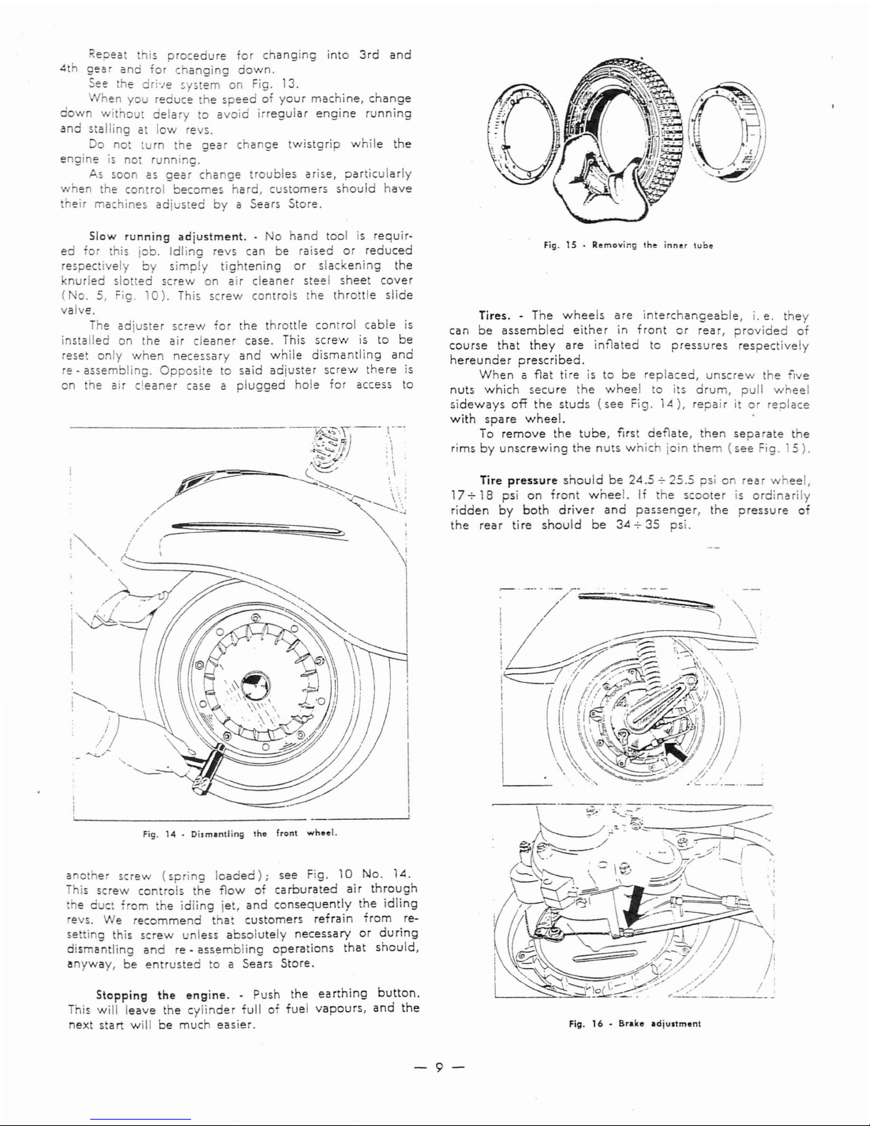
Fig.15•
Removing
Ihe
inner
lube
Tires. - The
wheels
are
interchangeable,
i.e.they
can
be
assembled
either
in
front
or
rear,
provided
of
course
that
they
are
inflated
to
pressures
respectively
hereunder
prescribed.
When
a flat
tireisto
be
replaced,
unscrew
the
five
nuts
which
secure
the
wheel
to its
drum,
pull
wheel
sideways
off
the
studs
(see
Fig.
14),
repa
ir i
or
replace
with
sparewheel.
To
remove
the
tube,
first
deflate,
then
separate
the
rimsbyunscrewing
the
nuts
which
join
them
(see
Fig.
5).
Tire
pressure
should
be
24.5.,.
25.5
psionrear
wheel,
17.,. 18 psi
on
front
wheel.
If
he
scooter
is
ordinarily
ridden
by
both
driver
and
passenger,
the
pressure
of
the
rear
tire
should
be
34.,.35
psi.
Fig.16-
Brake
adjustment
-9-
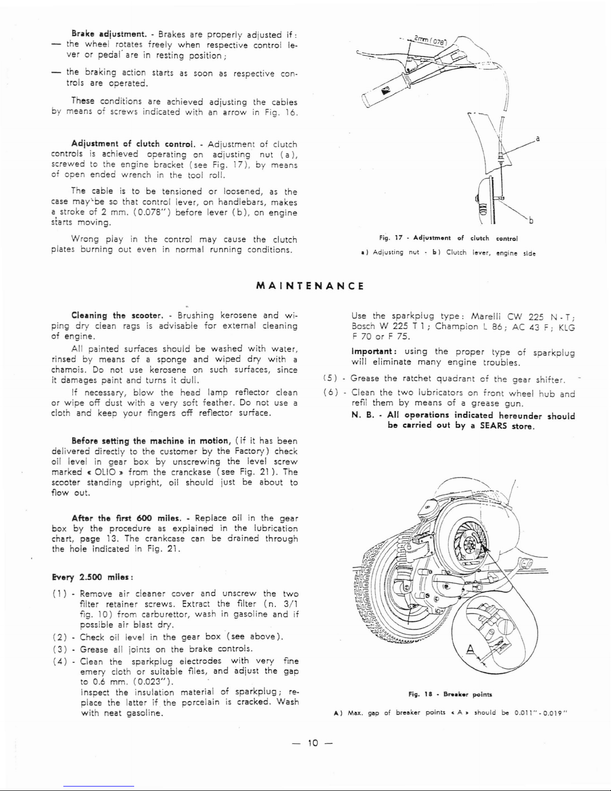
Br~ke
adjustment.
- Brakes
are
properly
adjusted
if:
the
wheel
r~tates
freely
when
respective
control
le-
verorpedal
areinresting
position;
the
brakino
action
starts
as
soon
as
respective
con-
trols
are
~Derated.
These
conditions
are
achieved
adjusting
the
cables
by
meansofscrews
indicated
with
an
arrowinFig.
16.
Adjustment
of
clutch
control.-Adjustment
of
clutch
controlsisachieved
operating
on
adjusting
nut
(a),
screwed
to
the
engine
bracket
(see
Fig.
17),
by
means
of
open
ended
wrench
in
the
tool roll.
The
cable
is
to
be
tensioned
or
loosened,
as
the
case
may'be
so
that
control
lever,
on
handlebars,
makes
a
strokeof2
mm.
(0.078")
before
lever
(b),
on
engine
starts
moving.
Wrong
play
in
the
control
may
cause
the
clutch
plates
burning
out
even
in
normal
running
conditions.
Fig.17-
Adjustm.nt
of
dutch
control
.)
Adiusting
nut-b)
Clutch
I~v~r.
~ngine
sld~
a
MAINTENANCE
Cleaning
the
scooter.-Brushing
kerosene
and
wi-
ping
dry
clean
ragsisadvisable
for
external
cleaning
of
engine.
All
painted
surfaces
should
be
washed
with
water,
rinsed
by
means
ofasponge
and
wiped
dry
with
a
chamois.
Do
not
use
kerosene
on
such
surfaces,
since
it
damages
paint
and
turnsitdull.
If
necessary,
blow
the
head
lamp
reflector
clean
or
wipe
off
dust
withavery
sof
feather.
Do
not
use
a
cloth
and
keep
your
fingers
off
reflector
surface.
Before
setting
the
machineinmotion,
(ifithas
been
delivered
di rectlytothe
customer
by
the
Factory)
check
oil level in
gear
box
by
unscrewing
the
level
screw
marked
«
OLIO»
from
the
cranckase
(see
Fig.
21
).
The
scooter
standing
upright,
oil
should
just
be
about
to
flow
out.
After
the
first
600
miles.-Replace
oil in
the
gear
box
by
the
procedure
as
explained
in
the
lubrication
chart,
page
13. The
crankcase
can
be
drained
through
the
hole
indicated
in Fig. 21.
Every 2.
.500
miles:
(1)-
Remove
air
cleaner
cover
and
unscrew
the
two
filter
retainer
screws.
Extract
the
filter
(n.
3/1
fig.
10)
from
carburettor,
washingasoline
and
if
possible
air
blast
dry.
(2)
-
Check
oil level in
the
gearbox
(see
above).
(3)
•
Grease
all joints
on
the
brake
controls.
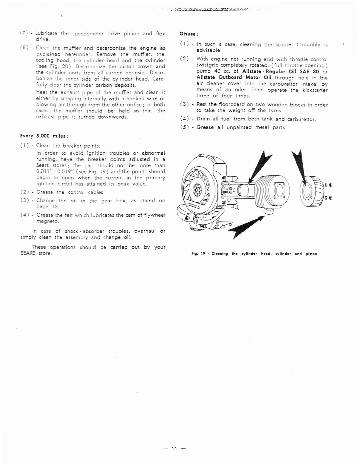
(4)
-
Clean
the
spa
rkplug
electrodes
with
very
fine
emery
cloth
or
suitable
files,
and
adjust
the
gap
to
0.6
mm.
(0.023").
.
InsDect
the
insulation
material
of
sparkplug;
re-
pla'ce
the
latterifthe
porcelainiscracked.
Wash
with
neat
gasoline.
Use
the
sparkplug
type:
Marelli
CW
225 N -
T;
Bosch W 225 T 1 ;
Champion
L
86;
AC 43
F;
KLG
F 70orF 75.
Important:
using
the
proper
type
of
spa
rkplug
will
eliminate
many
engine
troubles.
(S)
Grease
the
ratchet
quadrant
of
the
gear
shifter.
(6)
Clean
the
two
lubricators
on
front
wheel
hub
and
refil
them
by
means
ofagrease
gun.
N.B.- All
operations
indicated
hereunder
should
be
carried
out
by
a SEARS
store.
Fig.18- a....... r
points
A)
Max.
gapofbreaker
points
«A.
should
be
0.011"-0.019"
-
10-
e
speedometer
dive
pinion
and
flex
(7)
ubricate
drive.
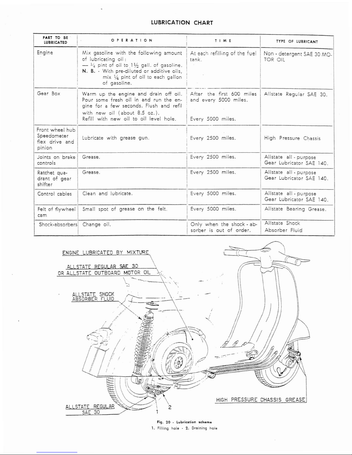
(8)
- Clea
the
muffler
and
decarbonize
the
engine
as
explained
hereunder.
Remove
the
muffler,
the
cooling
hood,
t e
cylinder
head
and
the
cylinder
(see
Fig.
20).
Decarbonize
the
piston
crown
and
the
cylinder
ports
from
all
carbon
deposits.
Decar-
bonize
the
inner
side
of
the
cylinder
head.
Care-
fully
clear
he
cylinder
carbon
deposits.
Hea
the
exhaust
pipeofthe
muffler
and
clean
it
ei
herbyscraping
internally
withahooked
wire
or
blowing
air
through
from
the
other
orifice;inboth
cases
the
muffler
should
be
held
so
that
the
exhaust
pipe
is
urned
downwards.
Every
5.000
miles:
(1)-Clean
the
breaker
points.
In
order
to
avoid
ignition
troubles
or
abnormal
running,
have
the
breaker
points
adjusted
in a
Sears
stores;
the
gap
should
not
be
more
than
0.01
"-
0.019"
(see
Fig.
9)
and
the
points
should
begin
to
open
when
the
current
in
the
primary
ig i ion circui
has
attained
its
peak
value.
(2)-Grease
he
control
cables.
(3)
Change
the
oil in
the
gear
box,
as
stated
on
page
13.
(4)
Grease
the
felt
which
lubricates
the
camofflywheel
magneto.
In
case
of
shock-absorber
troubles,
overhaul
or
simply
clean
the
assembly
and
change
oil.
These
operations
should
be
carried
out
by
you'r
SEARS
store.
Disuse:
(
1)
In
suchacase,
cleaning
the
scooter
throughly
is
advisable.
(2)
With
engine
not
running
and
with
throttle
control
twistgrip
completely
rotated,
(full
throttle
opening)
pump
40
cc.
of
Allstate·
Regular
Oil
SAE
30
or
Allstate
Outboard
Motor
Oil
through
hole
in
the
air
cleaner
cover
into
the
carburettor
intake,
by
means
of
an
oiler.
Then
operate
the
kicks
arter
three
of
four
times.
(3)
- Rest
the
floorboard
on
two
wooden
blocksinorder
to
tllke
the
weight
off
the
tyres.
(4)
• Drain all
fuel
from
both
tank
and
carburet
or.
(5)
Grease
all
unpainted
metal
parts.
Fig. 19 - Cleaning
th.
cylind.r
h.ad,
cylinder and pilton
-11
-
LUBRICATION CHART
PART
TO
BE
.
I
OPERATION
I
I
LUBRICATED
I
I
T I
III
E
TYPEOFLUBRICANT
Engine
Mix
gasoline
with
the
following
amount
i
At
each
refillingofthe
uel
i
Non·
detergent
SAE30MO-
I
I
of
lubricating
oil:
!
tank.
I
TOR OIL
-
l~
pintofoil
to.l
V:!
gall.ofgasoline.
I
N. B
..
With
pre-dilutedoradditive
oils,
I
i
mix %
pintofoil to
each
gallon
;
I
of
gasoline.
I
i
._-_.
Gear
Box
Warm
up
the
engine
and
drain
off
oil.
i
Af
er
the
first
600
miles
Allsta
e
Regular
SAE
30.
Pour
some
fresh
oil
in
and
run
the
en-iand
every
5000
miles.
gine
forafew
seconds.
Flush
and
refil
with
new
oil
(about
8.5
oz.).
i
I
Refill
with
new
oil
to
oil
level
hole.
I
Every
5000
miles.
-
Front
wheel
hub
I
Speedometer
!
Lubricate
with
grease
gun.
Every
2500
miles.
High
Pressure
Chassis
flex
drive
and
i
i
pinion
,
Joints
on
brake
Grease.
Every
2500
miles.
Allstate
all -
purpose
controls
Gear
Lubricator
SAE
140.
Ratchet
qua-
Grease.
Every
2500
miles.
Allstate
all -
purpose
drant
of
gear
Gear
Lubricator
SAE
140.
shifter
i
Control
cables
Clean
and
lubricate.
i
Every
5000
miles.
Allstate
all -
purpose
i
Gear
Lubricator
SAE
40.
Feltofflywheel
Small
spot
of
the
felt.
I
Every
5000
miles.
Allstate
Bearing
Grease.
grease
on
I
I
cam
I
Shock-absorbers
Change
oil.
I
Only
when
the
shock-ab-
Allstate
Shock
!
sorber
is
out
of
order.
Absorber
Fluid
ALLSTATE
SHOCK
ABSORBER
fLUID
ALLSTATE
REGULAR
SAE
30
ENGINE
LUBRICATED
BY
MIXTURE
\
\
1
OR
ALLSTATE
OUTBOARD
MOTOR
OIL-'".
\
--.
'-"--...-~
.~..~.
\;.
~
'L
f (
;;
I
\
;
~"
HIGH
PRESSURE
CHASSIS
GREASE
Fig_20. Lubrication scheme
1.
Filling
hole.2.
Dr.ining
hole
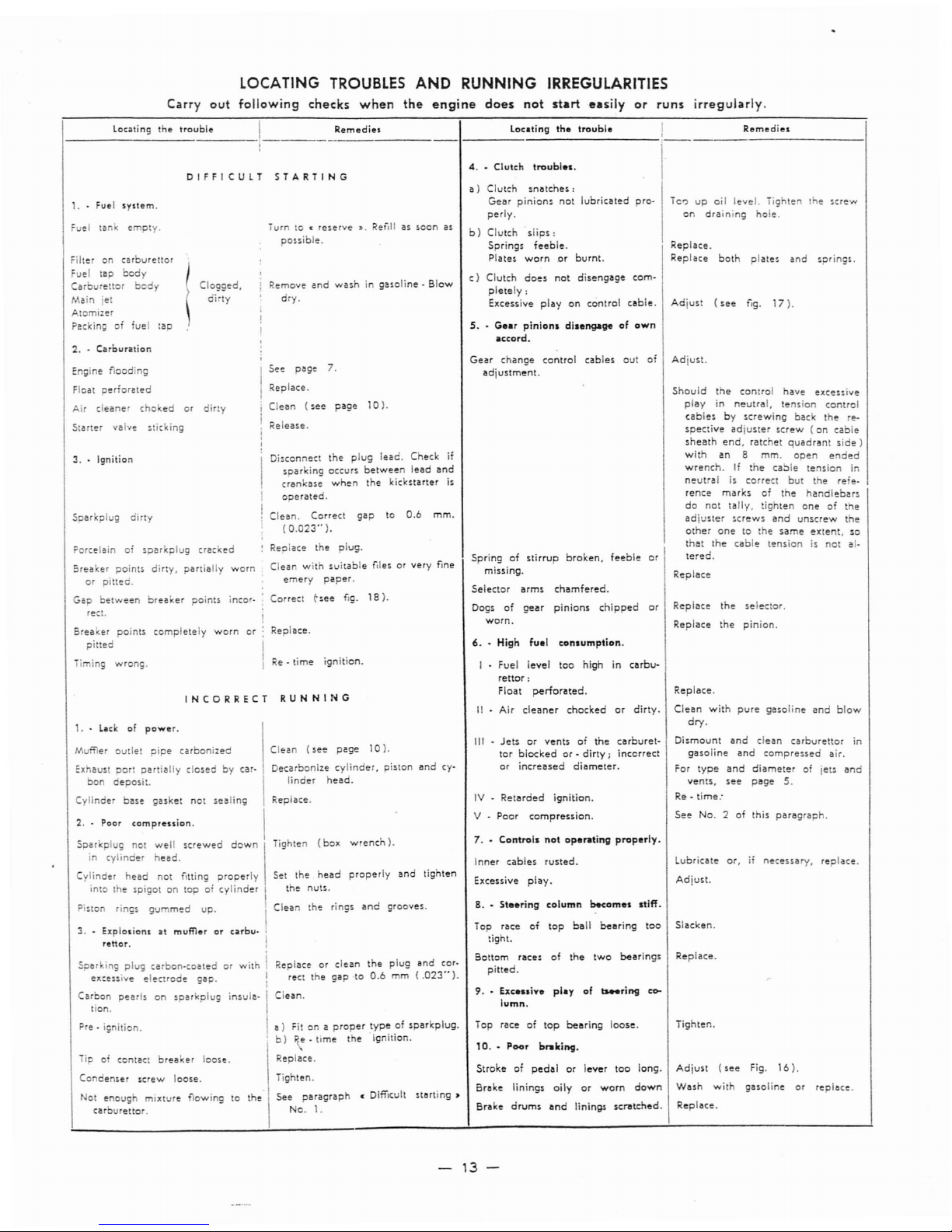
LoeA
T1NG
TROUBLES
AND
RUNNING IRREGULARITIES
Carry
out
following
checks
when
the
engine
does
not
start
easily
or
runs
irregularly.
Locati ng
the
trouble
I
R.emedies
Loc.ting
the
trouble!
Remedies
1---------.----
1
-------.---------1--------------:---------------1
4.•Clulch
trouble
•.
DIFFICULT
STARTING
INCORRECT
RUNNING
1. -
Lockofpower.
Tur toc:reserve
:l.
Refill as
~oon
as
po,sible.
I
See
page
7.
i
Replace.
replace.
iighten.
Adjust
(see
Fig.
16).
Wash
with
gasoline
or
Replace.
Replace.
Clean
with
pure
gasoline
and
blow
dry.
Replace
the
seleclor.
Replace
the
pinion.
Replace.
See
No.2of
this
paragraph.
Adjust.
Dismount
and
clean
carburettor
in
gasoline
and
compressed
air.
For
type
and
diameter
of
jets
and
vents,
see
page
5.
Re-time:
Lubricate
or,ifnecessary.
replace.
Slacken.
Should
the
control
have
excessive
play
in
neutral,
tension
control
cablesbyscrewing
back
the
re-
spective
adjuster
screw
(on
cable
sheath
end,
ratchet
quadrant
side)
with
an
8
mm.
open
ended
wrench.tfthe
cable
tension
in
neutraliscorrect
but
the
re'e·
rence
marks
of
the
handlebars
do
not
tally,
tighten
oneofthe
adjuster
,crew,
and
unscrew
the
ocher
onetothe
same
extent,
so
that
the
cable
tensionisnot
ai-
lered.
Replace
Adjust.
Replace.
Replace
both
plates
and
spring'.
Adjust
(see
f,g.
17).
Te')upoil
level.
Tighten
the
screw
on
draining
hole.
6.
High
fuel
consumption.
I
Fuel
level
too
highincarburettor:
Float
perforated.
II
Air
cleaner
chocked
or
dirty.
Inner
cables
rusted.
Excessive
play.
8
.•
Steering
column
become••tiff.
Top
raceoftop
bearing
loose.
III -
Jetsorventsofthe
carburet-
tor
blockedor-
dirty;
incorrect
or
increased
diameter.
7.•Control.
not
operating
properly,
9
.•
Exce
..inployof_ring
c0-
lumn.
Springofstirrup
broken,
feeble
or
missing.
Selector
arms
chamfered.
Dogsofgear
pinions
chipped
or
worn.
IV
-
Retarded
ignition.
V -
Poor
compression.
Gear
chanoe
control
cables
out
of
adjustm;nt.
10
.•
Poor
braking.
Strokeofpedalorlever
too
long.
Brake
linings
oilyorworn
down
Brake
drums
and
lininit'
SCrlltcned.
Top
raceoflop
ball
bearing
too
light.
Bottom
racesofthe
two
bearings
pitted.
5.
-
Gear
pinion.
di.engageofown
.ccord.
a)
Clutch
snotches:
Gear
pinions
not
lubricated
pro·
perly.
b)
Clutch
slips:
Springs
feeble.
Plates
wornorburnt.
c}
Clutch
does
not
disengage
com-
pletely:
Excessive
playoncontrol
cable.
mm.
gap
to
0.6
Replace.
Tighten.
See
paragraph
• Difficult
starting»
No.1.
Replaceorclean
the
plug
and
cor·
rect
the
gap
to
0.6mm(.023'·).
Clean.
a)
Fitona
proper
typeofsparkplug.
b)Re-
time
the
ignition.
Clean
the
ring,
and
grooves.
Tighten
(box
wrench).
Set
the
head
properly
and
tighten
the
nuts.
Replace.
Clean
(see
page
10).
Decarbonize
cylinder,
piston
and
cy-
linder
head.
Clean.
Correct
(0.023"
).
:
Replace
the
plug.
Clean
with
suitable
flies
or
very
fine
emery
paper.
Correct
(-see fig.
18).
!
:
Replace.
I
I
Re-time
ignition.
,
,
Remove
and
washingasoline-Blow
dry.
Clean
(see
page
10).
i
Release.
i
!
I
Disconnect
the
plug
lead.
Check
if
I
sparking
occurs
between
lead
and
crankase
when
the
kickstarter
is
!
operated.
!
Clogged,
dirty
Cylinder
ba,e
gasket
not
sealing
2.
Poor
compression.
I
Soarkplug
not
well
screwed
down
\
in
cylinder
head.
Cylinder
head
not
fitting
properly
into
the
spigotontop0'cylinder
I
Piston
rings
gu
med
up.
I
3.•Explosionsatmufflerorcarburettor.
!
Sparking
plug
carbon-coatedorwith
i
excessive
electrode
gap.
I
Carbon
pearl,onsparkplug
insula-,'
tion.
Pre -
ignition.
i
iip
of
contact
breaker
loose.
Condenser
screw
loose.
Not
enoug'
mixture
flowing
to
carburettor.
Muffler
outlet
pipe
carbonized
:xhaust
pOr!
partially
closedbycar·
bo
oeposit.
Breaker
points
completely
worn
or
pitted
3..Ignition
Timing
wrong.
Porcelain0sparkplug
cracked
Breaker
points
dirty,
partially
worn
or
pitted.
Gap
between
breaker
points
incor·
rect.
Engine
flooding
Float
perforated
Air
cleaner
choedor
dirty
Starter
vaIve
'tick
ing
Sparkplug
dirty
Filteroncarburettor
Fuel
tap
body
Carboetor
bedy
Main
jet
Atomizer
Packingoffuel
tap
2.-Carcuntion
1. Fuel
system.
~
ueItan
empty.
-
13-
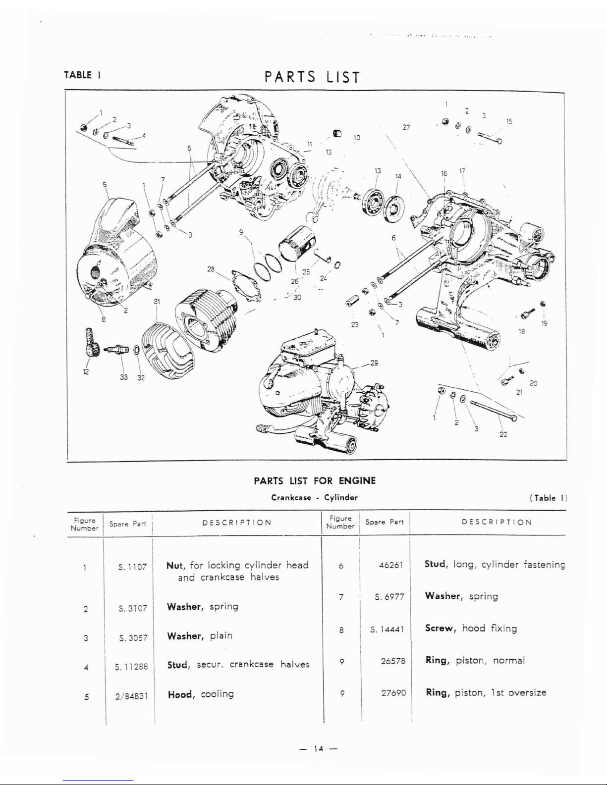
TABLE
I
PARTS LIST
2
"
@
15
27
@
,I:)
10
\
-.
~
"
16
17
;
18
.
-----
" (,;
"
/~.
/~
21
2C
1
\\~,
2 \ \
3 ,
22
- 14 -
9
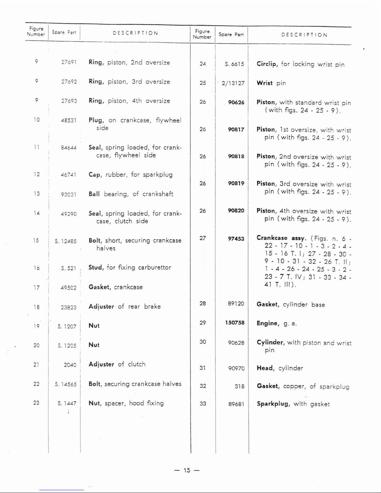
Figure I
umbe
Spare
Par
DESCRIPTIO
I
~~~~:r
I
Spare
Part
DESCRIPTION
9 2769
Ring,
piston,
2nd
oversize
I
24
I
S.6615
!
Circlip,
for
locking
wrist
pin
90626
9
9
10
27692
27693
48531
Ring,
piston,
3rd
oversize
Ring,
piston,
4th
oversize
Plug,
on
crankcase,
f1ywheel
side
25
26
26
I
I'
2/13127
I
I
I
90817
Wrist
pin
Piston,
with
standard
wrist
pin
(with
figs.
24-25-9).
Piston,1st
oversize,
with
wrist
pin
(with
figs.
24-25
-
9).
11
84644 Seal,
spring
loaded,
for
crank-
case,
f1ywheel
side
26
90818
Piston,
2nd
oversize
with
wrist
pin
(with
figs.
24-25
-
9).
12
46741
Cap,
rubber,
for
sparkplug
3
93031
Ball
bearing,
of
crankshaft
26
90819
Piston,
3rd
oversize
with
wrist
pin
(witf:
figs.
24-25
-
9).
14
49290
Seal,
spring
loaded,
for
crank-
case,
clutch
side
26
90820
Piston,
4th
oversize
with
wrist
pin
(with
figs.
24-25
-
9).
15
16
17
S.
12485
S.521
49502
Bolt,
short,
securing
crankcase
halves
Stud,
for
fixing
carburettor
Gasket,
crankcase
27
97453
.
Crankcase
assy.
(Figs.
n. 6 .
22
- 17 - 10 - 1 - 3 - 2 - 4 -
15 - 16T.Ii
27
- 28 - 30 -
9
-
10-31
- 32 - 26T.II
i
1 - 4 -
26
-
24.25
- 3 - 2 .
23
- 7T.IVi31
- 33 - 34 -
41
T.
III).
2040
23823
S,1205
I
S.
4565 I
Head,
cylinder
Cylinder,
with
piston
and
wris
pin
Engine,
g.
a.
Gasket,
copper,
of
sparkplug
Gasket,
cylinder
base
318
90970
89120
1507581
90628
32
30
31
28
29
Nut
Bolt,
securing
crankcase
halves
Adjuster
of
clutch
Nut
Adjuster
of
rear
brake
I
I'
S.1207
I
I
I
I
19
18
20
2
22
23
S.1447
Nut,
spacer,
hood
fixing
33
89681
Sparkplug,
with
gaske
-
15-
 Loading...