

Page 1

삼 흥
정 판
DIVISION 20
BASIC FIELD MANUAL
FOR
MICROWAVE OVEN
MODEL 721.62252200 / 721.62252201
721.62259200 / 721.62259201
721.62253200 / 721.62253201
721.63263300 / 721.63263301
May, 2005
MODEL 721.62252
721.62259
721.62253
721.63263
Page 2

CAUTION
WARNING TO SERVICE TECHNICIANS
PRECAUTIONS TO BE OBSERVED BEFORE
AND DURING SERVICING TO AVOID
POSSIBLE EXPOSURE TO EXCESSIVE
MICROWAVE ENERGY
a. Do not operate or allow the oven to be operated with the door open.
b. Make the following safety checks on all ovens to be serviced before activating the magnetron or other
microwave source, and make repairs as necessary; (1) Interlock operation, (2) proper door closing, (3)
seal and sealing surfaces (arcing, wear, and other damage), (4) damage to or loosening of hinges and
latches, (5) evidence of dropping or abuse.
c. Before turning on microwave for any service test or inspection within the microwave generating
compartments, check the magnetron, wave guide or transmission line, and cavity for proper alignment,
integrity, and connections.
d. Any defective or misadjusted components in the interlock, monitor, door seal, and microwave
generation and transmission systems shall be repaired adjusted by procedures described in this
manual before the oven is released to the owner.
e. A Microwave leakage check to verify compliance with the Federal performance standard should be
performed on each oven prior to release to the owner.
• Proper operation of the microwave ovens requires that the magnetron be assembled to the wave guide and
cavity. Never operate the magnetron unless it is properly installed.
• Be sure that the magnetron gasket is properly installed around the dome of the tube whenever installing the
magnetron.
• Routine service safety procedures should be exercised at all times.
• Untrained personnel should not attempt service without a thorough review of the test procedures and safety
information contained in this manual.
-1-
Page 3

-2-
MODEL 721.62252
721.62259
721.62253
721.63263
MECHANICAL SERVICE INFORMATION
TABLE OF CONTENTS
1. Adjustment Procedures
----------------------------------------------------------------------------------------------------------------------------------
3
2. Precautions on Installation
------------------------------------------------------------------------------------------------------------------------------
5
3. General Precautions in Use
----------------------------------------------------------------------------------------------------------------------------
5
4. Trial Operation
----------------------------------------------------------------------------------------------------------------------------------------------
5
5. Specifications
------------------------------------------------------------------------------------------------------------------------------------------------
6
6. Overall Circuit Diagram
----------------------------------------------------------------------------------------------------------------------------------
7-9
7. Operating Procedures
------------------------------------------------------------------------------------------------------------------------------------
10-11
8. Procedure for Measuring Microwave Energy Leakage
---------------------------------------------------------------------------------------
12-13
9. Disassembly Instructions
--------------------------------------------------------------------------------------------------------------------------------
14-18
10. Interlock Continuity Test
-------------------------------------------------------------------------------------------------------------------------------
19
11. Test and Checkout Procedures, and Troubleshooting
A. Test Procedures
------------------------------------------------------------------------------------------------------------------------------------
20-22
B. Checkout Procedures
-----------------------------------------------------------------------------------------------------------------------------
23-25
C. Troubleshooting
-------------------------------------------------------------------------------------------------------------------------------------
26-30
12. Exploded View
--------------------------------------------------------------------------------------------------------------------------------------------
31-41
13. Part Reference list
---------------------------------------------------------------------------------------------------------------------------------------
42-49
FOREWORD
Read this Manual carefully. Failure to adhere to or observe the information in this Manual may result in exposing yourself to
the Microwave Energy normally contained within the oven cavity.
Page 4

1. ADJUSTMENT PROCEDURES
To avoid possible exposure to microwave energy
leakage, adjust the door latches and interlock switches,
using the following procedure.
ONLY AUTHORIZED SERVICE PERSONNEL
SHOULD MAKE THIS ADJUSTMENT.
The Interlock Monitor and Primary Interlock Switch acts
as the final safety switch protecting the user from
microwave energy. The terminals between “COM” and
“NC” of the Interlock Monitor must close when the door
is opened. After adjusting the Interlock Monitor Switch,
make sure that it is correctly connected. See Figures 1-a
and 1-b throughout this procedure.
CHECK THE DOOR LATCH AND SWITCH
CLOSINGS.
NOTE: The outer cover of the microwave oven is
removed.
(1) Set the microwave oven on its side so that you can see
the latch board and the switches, as shown in
Figure 1-a.
(2) Close the door tightly and check gaps A and B to be
sure they are no more than 1/64” (0.5 mm). See Figure
1-b for close-up view of gaps A and B (door latches).
If all gaps are less than 1/64” (0.5 mm), adjustment of
the latch board may not be necessary. Go to Steps 5
and 6 to check the sequence of the switches.
NOTE: To correct sequence of the Primary Interlock
Switch, Secondary Interlock Switch and the
Interlock Monitor Switch is very important.
If any gap is larger than 1/64” (0.5 mm), you will need to
adjust the latch board-U, L. Go to step 3 and follow all
steps in order.
ADJUST THE LATCH AND SWITCH CLOSINGS
(3) Loosen the two screws holding the plastic latch board as
shown.
(4) With the oven door closed tightly, move the latch board
upward toward the top of the oven and/or away from the
door latch until the gaps are less than 1/64” (0.5 mm).
Hold the latch board tightly in this position until you
check the sequence of the switches in steps 5 and 6.
TEST THE LATCH AND SWITCH SEQUENCE
(5) Open the oven door slowly. Watch the door latch, the
Primary Switch. Release Rod and Lever on the switches
to make sure they are zero to the body of the switches
in the following sequence:
- Primary Interlock Switch
- Secondary Interlock Switch
- Interlock Monitor Switch
Adjust the latch board until the switches operate in this
sequence. See Steps 3 and 4.
(6) Close the oven door slowly and be sure it is tightly
closed. Watch the three switches to make sure they are
zero to the body of the switches in the following
sequence:
- Interlock Monitor Switch
- Primary Interlock Switch
- Secondary Interlock Switch
NOTE: The Interlock Monitor Switch is an added safety
check on the Primary and Secondary Interlock
Switches. If the Primary and Secondary Interlock
Switches allow the oven to operate with the door
open, the Monitor Switch will blow the fuse.
(7) When you achieve the proper sequence of switches in
Steps 5 and 6, tighten the latch board screws at that
point.
TEST THE MICROWAVE ENERGY LEAKAGE
(8) Using a survey meter, make sure the microwave energy
is below 5 mW/cm.sq.
-3-
Page 5
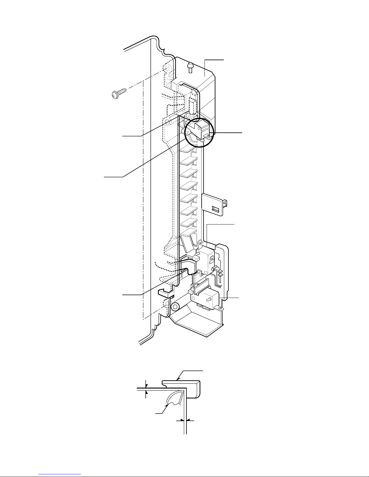
-4-
LATCH BOARD
MONITOR
INTERLOCK
SWITCH
PRIMARY
INTERLOCK
SWITCH
SECONDARY
INTERLOCK
SWITCH
LATCH
LATCH BOARD
0-1/64"
0-1/64"
A
DOOR LATCH
DOOR LATCH
Figure 1-a
Figure 1-b
Page 6
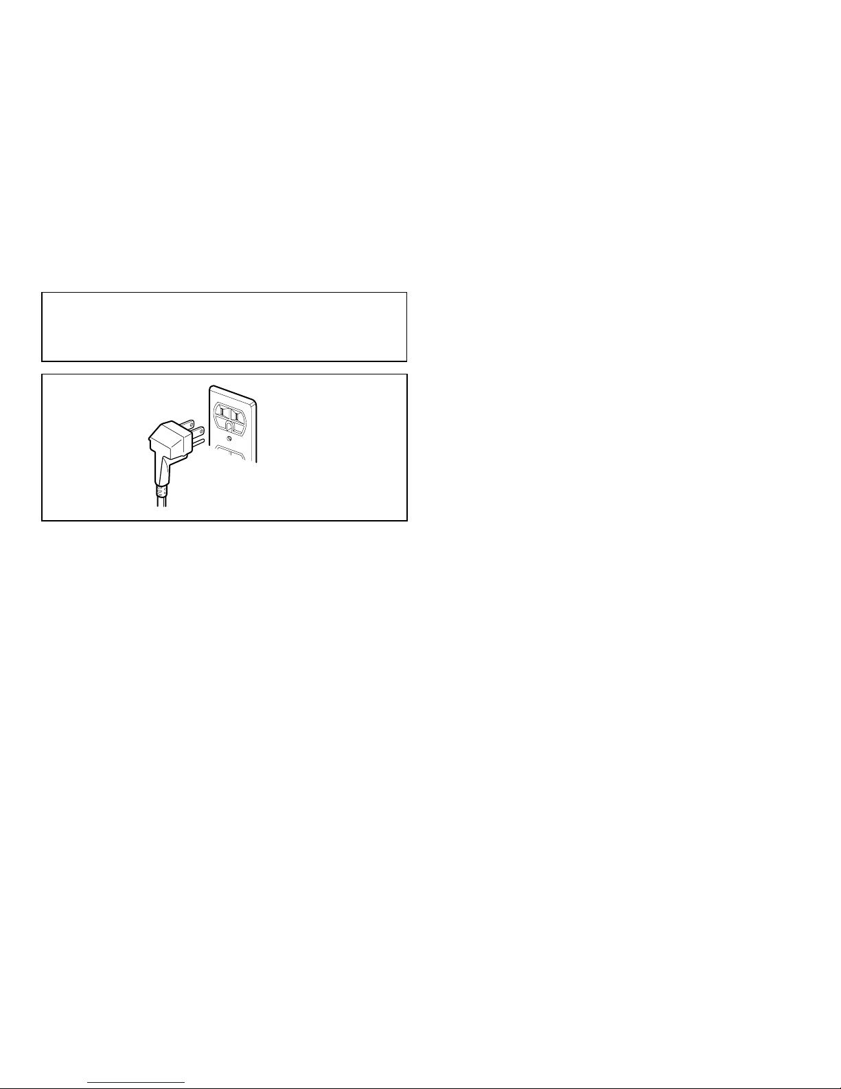
2. PRECAUTIONS ON INSTALLATION
(Figure 2)
A. Plug the power supply cord into a 120 V AC, 60 Hz,
single-phase power source with a capacity of at least 15
amperes.
B. Since the unit weights about 26 lbs, be sure to place it
on a sturdy and flat surface.
C. Avoid placing the unit in a location where there is direct
heat or splashing water.
D. Place the unit as far away as possible from TV, radio,
etc. to prevent interference.
CAUTION
3. GENERAL PRECAUTIONS IN USE
A. Never operate the unit when it is empty. Operating the
oven with no load may shorten the life of the magnetron.
Whenever cooking dry foods (dried fish, bread, etc.) or a
small amount of food, be sure to put a glass of water
into the cooking compartment. The turntable tray may
become hot after operating, be careful when touching it.
B. Aluminum foil should be avoided because it will disrupt
cooking and may cause arcing. However, small pieces
may be used to cover some parts of food to slow the
cooking. Any aluminum foil used should never be closer
than 2.5 cm to any side wall of the oven.
4. TRIAL OPERATION
After installation, the following sequences and results
should be checked carefully.
A. Put a container filled with water (about 1 liter) into the
oven, and close the door tightly.
B. Touch the STOP/CLEAR and the COOK TIME keys.
C. Set cooking time for 10 minutes by touching “1” and
then “0” three times. “1000” appears in the display
window.
D. Touch the START key.
Make sure the cavity light comes on. The unit will begin
cooking and the display window will show the time
counting down by seconds.
E. After about 5 minutes, make sure the primary interlock
switch, the secondary interlock switch and the interlock
monitor and oven lamp switch operate properly by
opening and closing the door several times. Touch the
START key each time the door is closed.
F. Continue operating the unit. Four long beep sound signal
is heard when the time is up. The unit will shut off
automatically.
G. Confirm the water is hot.
H. Finally, measure the output power according to
“POWER OUTPUT MEASUREMENT” on page 13.
5. FEATURES AND SPECIFICATIONS
A. The safety systems incorporated in this model are:
(1) Primary interlock switch
(2) Secondary interlock switch
(3) Interlock monitor switch
(4) Choke system
(5) Magnetron thermostat
(6) Oven cavity thermostat
(Note: This thermostat located on the oven cavity will
open and stop the unit from operation only if a high
temperature is reached, such as, a fire created by
overcooking food.)
B. Any one of 10 power output levels ranging 100W to
1000W can be selected by the touch control and
electronic computer system.
C. Cooking time can be displayed on the digital readout.
D. Three different cooking stages can be set. The oven
remembers three cooking stages and changes from one
cooking stage to another. This is made possible with the
memory function of the microprocessor.
-5-
This unit is equipped with a 3-prong plug for your
safety. If the wall outlet is a grounded 3-hole type, the
unit will be grounded automatically.
Three-Pronged(Grounding)
Plug
Figure 2
Properly Polarized and
Grounded
Outlet
Page 7

-6-
Rated Power Consumption
---------------------------------
1450W maximum
Output
--------------------------------------------------------------
1100W maximum (*IEC60705 Rating standard)
Adjustable 110W through 1100W, 10 steps
Frequency
--------------------------------------------------------
2450 MHz ± 50 MHz
Power Supply
---------------------------------------------------
120V AC, 60Hz
Rated Current
---------------------------------------------------
12.5 Amp.
Magnetron Cooling
--------------------------------------------
Forced Air Cooling
Microwave Stirring
----------------------------------------------
Turntable
Rectification
------------------------------------------------------
Rectification Voltage Doubler Half-Wave
Door Sealing
-----------------------------------------------------
Choke System
Safety Devices
--------------------------------------------------
Thermostat:
Open at 90°C ± 5°C
Close at 75°C ± 5°C
Fuse(20A)
Primary Interlock Switch
Secondary Interlock Switch
Interlock Monitor
Magnetron
--------------------------------------------------------
2M282J
High Voltage Capacitor
--------------------------------------
Capacitor: 1.05µF, 2.1 KV Ac
High Voltage Diode
-------------------------------------------
350mA, 9.0 KV
Cavity Lamp
-----------------------------------------------------
125 V, 20 W
Timer
---------------------------------------------------------------
Digital, up to 99 mim. 99 sec. (in each cooking stage)
Tray
-----------------------------------------------------------------
Tempered Safety Glass
Overall Dimensions
-------------------------------------------
203/19"(W) x 1117/20"(H) x 1621/46"(D)
Oven Cavity Size
----------------------------------------------
1413/75"(W) x 910/27"(H) x 15"(D)
Effective Capacity of Oven Cavity
-----------------------
1.2 Cu.ft.
Accessories
------------------------------------------------------
Use and Care Manual ,Turntable,
Rotating Ring Assembly.
SWITCH CHART
NOTE: Use the above switch chart with circuit diagram on page 7.
SPECIFICATIONS
SWITCH MODE
CONDITIONS
DOOR OPEN
DOOR CLOSED
PRIMARY SECONDARY INTERLOCK
INTERLOCK INTERLOCK MONITOR
SWITCH SWITCH SWITCH
COM COM COM
NO NO NC
∞∞0
00∞
Page 8
-7-
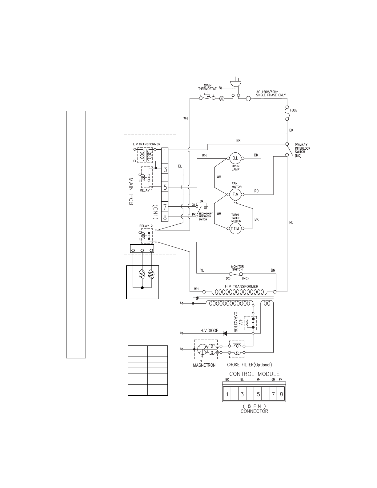
6. OVERALL CIRCUIT DIAGRAM
A (I). SCHEMATIC DIAGRAM *Check the Model No.
IMPORTANT SAFETY NOTE: THE SHADED AREAS ON THIS SCHEMATIC DIAGRAM INCORPORATE SPECIAL FEATURES
IMPORTANT FOR PROTECTION FROM MICROWAVE RADIATION, FIRE, ELECTRICAL SHOCK, AND
HAZARDS. WHEN SERVICING IT IS ESSENTIAL THAT ONLY MANUFACTURER S SPECIFIED PARTS
BE USED FOR THE CRITICAL COMPONENTS IN THE SHADED AREAS OF THE SCHEMATIC DIAGRAM.
NOTICE: SINCE THIS IS BASIC SCHEMATIC DIAGRAM, THE VALUES OF COMPONENTS AND
SOME PARTIAL CONNECTIONS ARE SUBJECT TO CHANGE FOR IMPROVEMENT.
WH
SYMBOL
NOTE:
1. DOOR IS OPEN.
2.RS: SENSING
ELEMENT
RC: COMPENSATING
ELEMENT
3. WIRE COLOR.
COLOR
WHITE
BLACK
YELLOW
PINK
BLUE
GREEN
BROWN
BK
YL
PK
RED
RD
BL
GN
BN
WH RD
RC RS
HUMIDITY
SENSOR
BK
321
Page 9
-8-
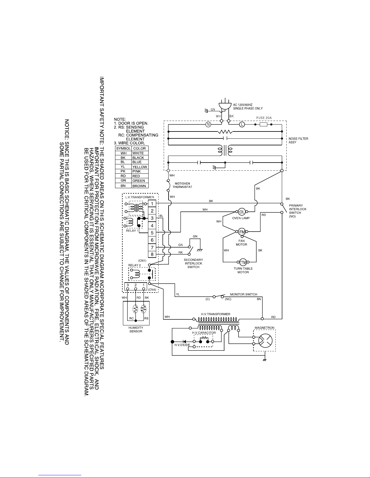
A (II). SCHEMATIC DIAGRAM *Check the Model No. (ADD Noise filter)
Page 10
-9-
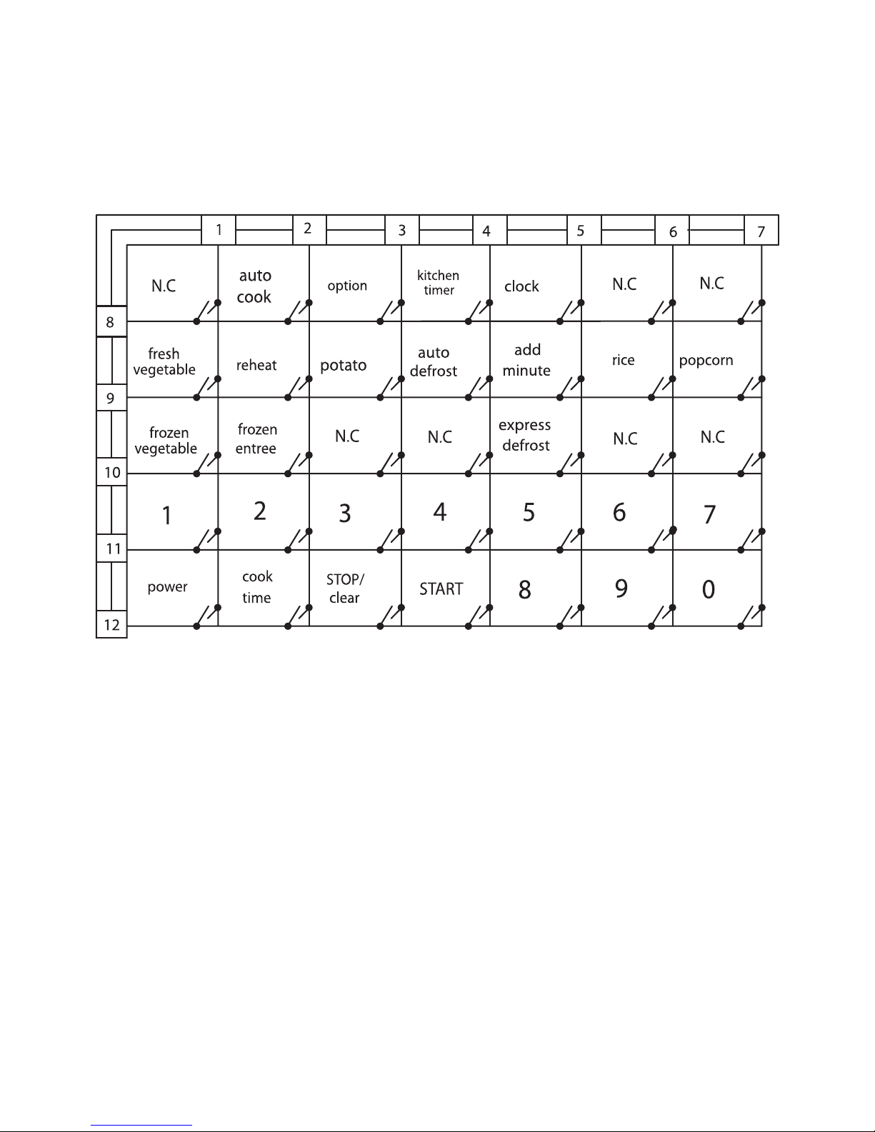
B. MATRIX CIRCUIT FOR TOUCH KEY BOARD
Figure 4
Page 11
-10-
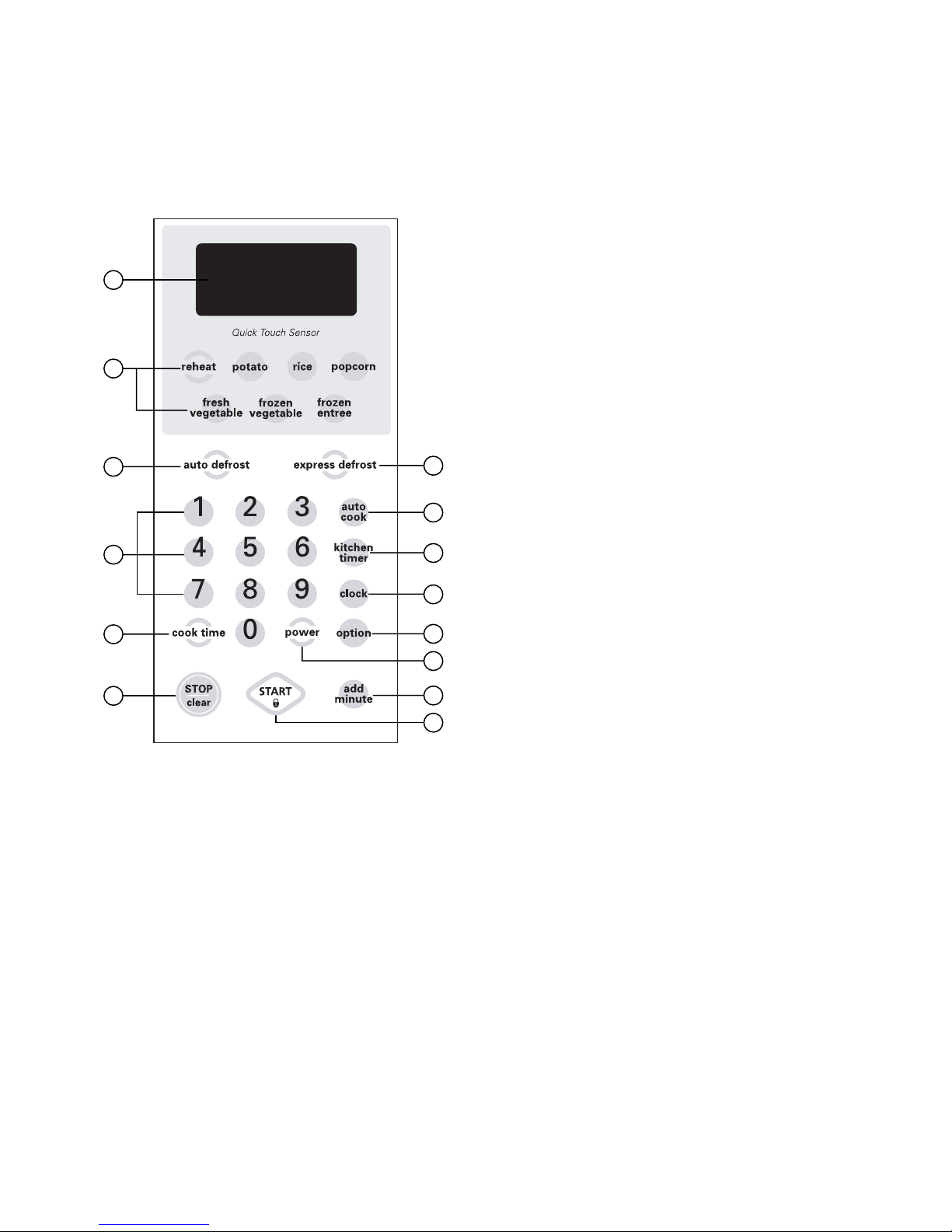
7. OPERATING PROCEDURES
A. OVEN CONTROL PANEL
Figure 5
7
8
9
10
11
12
13
14
3
4
5
6
2
1
1. DISPLAY. The Display includes a clock and
indicators that tell you time of day, cooking time
settings, and cooking functions selected.
2. QUICK TOUCH SENSOR. This pad allows you to cook
most of your favorite foods without having to select
cooking times and power levels.
3. AUTO DEFROST. This pad is an accurate defrosting
method for frozen meat, poultry and fish up to 6.0 lbs
or 4.0 kgs.
4. NUMBER PADS. Touch Number Pads to enter
cooking time, power level, quantities, or weights.
5. COOK TIME. Touch this pad to set a cooking time.
6. STOP/CLEAR. Touch this pad to stop the oven or
clear entries.
7. EXPRESS DEFROST. This pad provides you with the
quick defrosting method for 1.0 pound frozen foods.
8. AUTO COOK. Touch this pad to select programming
food items.
9. KITCHEN TIMER. Touch this pad to use your
microwave oven as a kitchen timer.
10. CLOCK. Touch this pad to enter the time of day.
11. OPTION. Touch this pad to change the oven's default
settings for sound, clock, scroll speed and Lbs/Kg.
12. POWER. Touch this pad to set a cooking power.
13. ADD MINUTE. Touch this pad to cook at 100% cook
power for 1 minute to 99 minute 59 seconds.
14. START. Touch this pad to start all entries (except the
Quick Touch Sensor, Express Defrost, Auto Cook and
Add Minute function which start automatically) and to
turn Child Lock on or off.
NOTE: A “beep” sounds when you touch a “key” on the control panel, to indicate that you have entered
a setting.
Page 12

B. EASY USE TABLE
(1) KITCHEN TIMER
1. Touch STOP/CLEAR.
2. Touch KITCHEN TIMER.
3. Touch correct number for time.
4. Touch START.
(2) CHILD LOCK
To set:
1. Touch STOP/CLEAR.
2. Touch “START” more than 4 seconds.
To cancel:
1. Touch STOP/CLEAR.
2. Touch “START” more than 4 seconds.
(3) QUICK TOUCH SENSOR
1. Touch STOP/CLEAR.
2. Touch QUICK TOUCH SENSOR Category.
(4) ADD MINUTE
1. Touch STOP/CLEAR.
2. Touch ADD MINUTE.
(5) OPTION
1. Touch STOP/CLEAR.
2. Touch OPTION.
3. Touch number from 1 to 4
Touch 1: SOUND ON/OFF
Touch 2: CLOCK ON/OFF
Touch 3: SCROLL SPEED
Touch 4: LBS/KG
(6) EXPRESS DEFROST
1. Touch STOP/CLEAR.
2. Touch EXPRESS DEFROST.
(7) AUTO DEFROST
1. Touch STOP/CLEAR.
2. Touch AUTO DEFROST.
Three different defrosting levels are provided.
Touch 1 : Meat
Touch 2 : Poultry
Touch 3 : Fish
3. Enter the weight of your food in decimal
increments from 0.1 to 6.0 pounds.
4. Touch START
5. At beeping, turn food over by following the
instructions in the manual.
6. After turning food over, touch START to resume
defrosting.
(8) TIMED COOKING
1. Touch STOP/CLEAR.
2. Touch COOK TIME.
3. Touch numbers for cooking time.
4. Touch POWER.
5. Touch number for cooking power level.
6. Touch START.
(9) MULTI-STAGE COOKING
1. Touch STOP/CLEAR.
2. Touch COOK TIME.
3. Touch numbers for cooking time.
4. Touch POWER.
5. Touch number for cooking power level.
6. Repeat steps 2-5 to set 2nd cooking stage.
7. Touch START.
-11-
Page 13
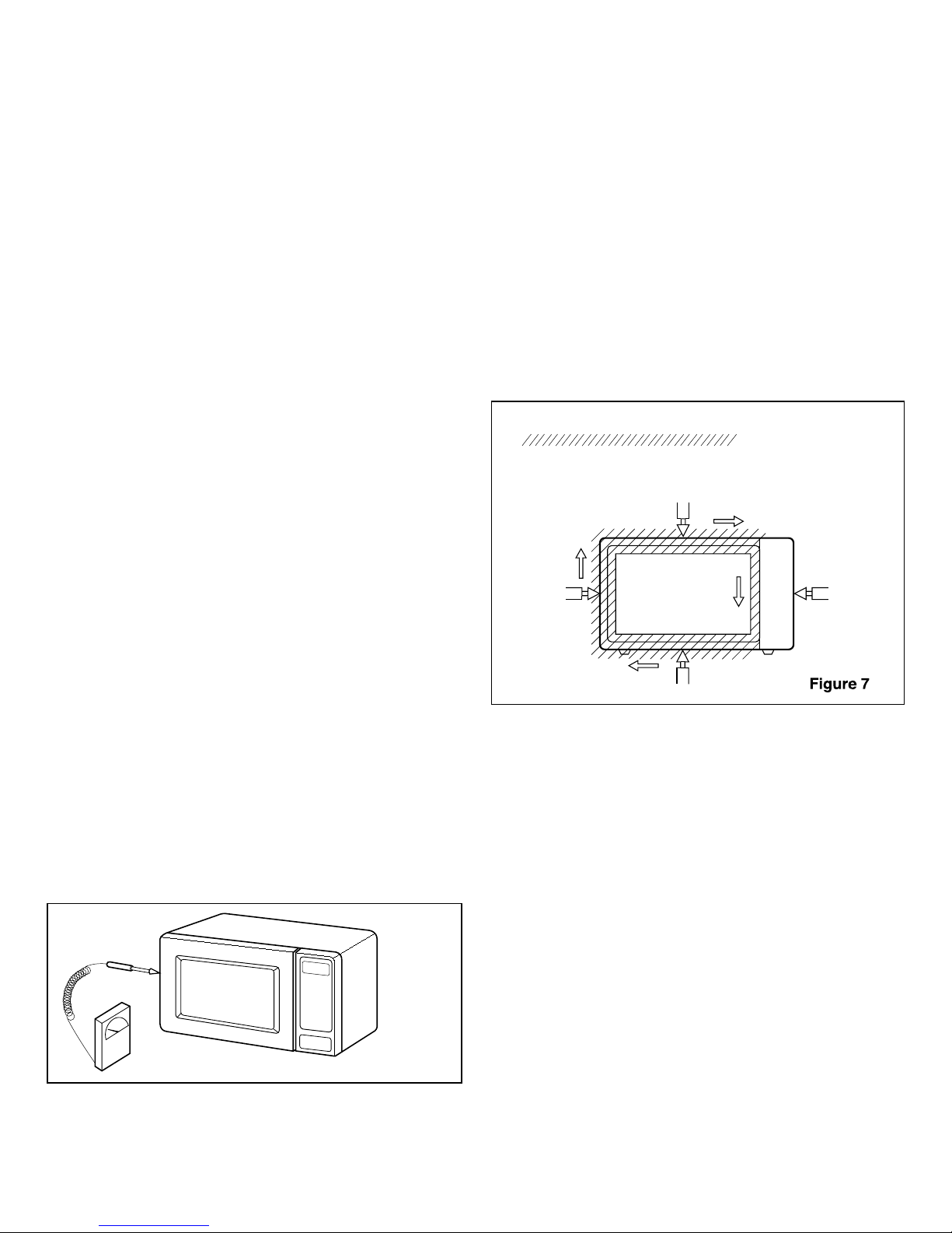
8. PROCEDURE FOR MEASURING MICROWAVE
ENERGY LEAKAGE
A. CAUTIONS
(1) Be sure to check a microwave emission prior to
servicing the oven if the oven is operative prior to
servicing.
(2) The service personnel should inform the manufacturer,
importer, or assembler of any certified oven unit found
to have a microwave emission level in excess of
5mW/cm.sq. and should repair any unit found to have
excessive emission levels at no cost to the owner and
should ascertain the cause of the excessive leakage.
The service personnel should instruct the owner not to
use the unit until the oven has been brought into
compliance.
(3) If the oven operates with the door open, the service
personnel should;
- Tell the user not to operate the oven
- Contact the manufacturer and CDRH (Center for
Devices and Radiological Health) immediately.
NOTE: Address on CDRH
Office of Compliance (HFZ-312)
Center for Devices and Radiological Health
1390 Piccard Drive
Rockville, Maryland 20850
(4) The service personnel should check all surface and vent
openings for microwave emission testing.
(5) Check for microwave energy leakage after every
servicing. The power density of the microwave radiation
leakage emitted by the microwave oven should not
exceed 1mW/cm.sq. And always start measuring of an
unknown field to assure safety for operating personnel
from radiation leakage.
NOTE: The standard is 5mW/cm.sq. while in the
customer’s home. 1mW/cm.sq. stated here is
manufacturer’s own voluntary standard for units in
customer’s home.
EQUIPMENT
• Electromagnetic energy leakage monitor (NARDA
8100B, HOLADAY HI 1501)
• 600cc glass beaker
• Glass thermometer 1000C
B. MEASURING MICROWAVE ENERGY LEAKAGE
(1) Pour 275 ± 15cc of 20 ± 5 °C water in a beaker which is
graduated to 600 cc, and place the beaker in the center
of the oven.
(2) Set the energy leakage monitor to 2450 MHz and use it
following the manufacturer’s recommended test
procedure to assure correct result.
(3) When measuring the leakage, always use the 2 inch
(5 cm) spacer supplied with the probe.
(4) Operate the oven at its maximum output.
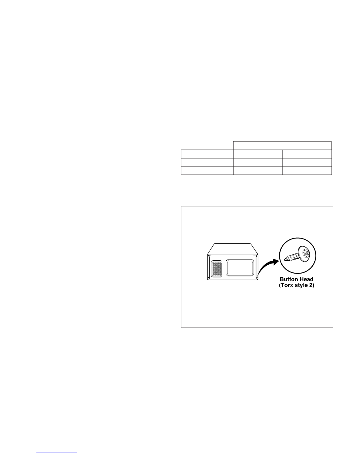
(5) Measure the microwave radiation using and
electromagnetic radiation monitor by holding the probe
perpendicular to the surface being measured. (See
Figure 7)
Move probe along shaded area.
Probe scanning speed
less than 2.5 cm/sec.
C. MEASUREMENT WITH THE OUTER CASE REMOVED
(1) When you replace the magnetron, measure for
microwave energy leakage before the outer case is
installed and after all necessary components are
replaced or adjusted. Special care should be taken in
measuring the following parts.
- Around the magnetron
- The waveguide
WARNING: AVOID CONTACTING ANY HIGH VOLTAGE
PARTS.
-12-
Figure 6
Page 14
D. MEASUREMENT WITH A FULLY ASSEMBLED OVEN
(1) After all components, including the outer panels, are
fully assembled, measure for microwave energy
leakage around the door viewing window, the exhaust
opening and air inlet openings.
(2) Microwave energy leakage must not exceed the values
prescribed below.
NOTES:
Leakage with the outer panels removed - less than
5mW/cm.sq. Leakage for a fully assembled oven
(Before the latch switch (primary) is interrupted) with the
door in a slightly opened position - less than
1 mW/cm .sq.
E. NOTE WHEN MEASURING
(1) Do not exceed meter full scale deflection.
(2) The test probe must be removed no faster than 1
inch/sec (2.5cm/sec) along the shaded area, otherwise
a false reading may result.
(3) The test probe must be held with the grip portion of the
handle. A false reading may result if the operator’s
hand is between the handle and the probe.
(4) When testing near a corner of the door, keep the probe
perpendicular to the surface making sure the probe
horizontally along the oven surface, this may possibly
cause probe damage.
F. RECORD KEEPING AND NOTIFICATION AFTER
MEASUREMENT
(1) After adjustment and repair of any microwave energy
interruption or microwave energy blocking device,
record the measured values for future reference. Also
enter the information on the service invoice.
(2) Should the microwave energy leakage not be more
than 1mW/cm.sq. after determining that all parts are in
good condition, functioning properly and genuine
replacement parts which are listed in this manual have
been used.
(3) At least once a year, have the electromagnetic energy
leakage monitor checked for calibration by its
manufacturer.
G. POWER OUTPUT MEASUREMENT
(1) Fill the test beaker with 59 °F(15 °C) ~ 75 °F(24 °C) 1 liter tap
water.
(2) Stir the water in the beaker with thermometer (°F or °C) and
measure temperature as T1.
(3) Place the beaker on the center of turntable.
(4) Set for one (1) minute and three (3) seconds and operate
the oven at high power.
NOTE: The additional three (3) seconds is to allow the
magnetron to begin generating power.
(5) When the heating is finished, stir the water again with
thermometer and measure the temperature of water as T2.
(6) Subtract T1 from T2, this will give you the temperature rise.
(7) The microwave power output is within specification, if the
temperature rise is as shown below:
(8) Power output will be influenced by line voltage of power
supply. Consequently, correct power output must be
measured within 120V AC ± 1 Volt while unit is operating.
SPECIAL TIP
• This oven used the button head screws.
• When you remove the screws, using the
tamper-resistant Torx driver have a
pin-in-head.
-13-
Line Voltage Degrees °F Degrees °C
120 V 18.9 ~ 25.2 10.5 ~ 14
108 V Min. 17.5 Min 9.7
Temperature Rise
Page 15
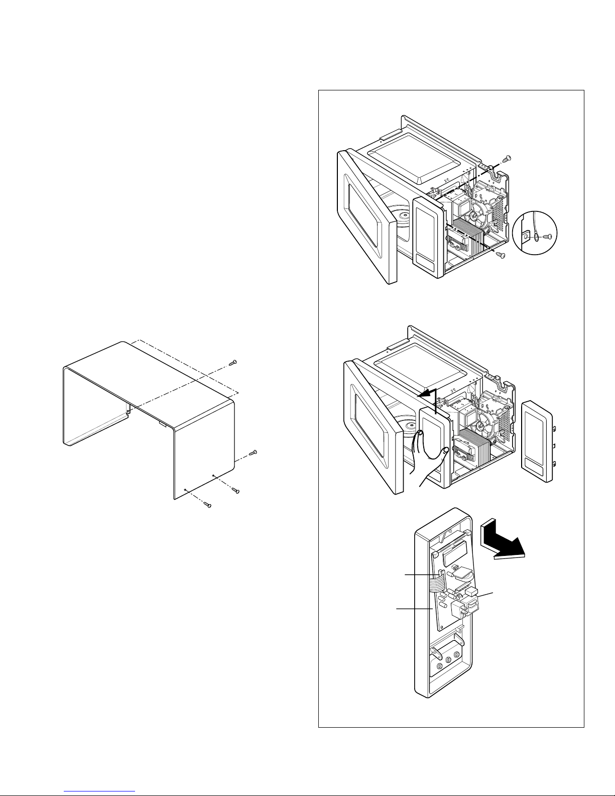
9. DISASSEMBLY INSTRUCTIONS
IMPORTANT NOTES:
UNIT MUST BE DISCONNECTED FROM ELECTRICAL
OUTLET WHEN MAKING REPAIRS, RE-PLACEMENTS,
ADJUSTMENTS AND CONTINUITY CHECKS. WAIT AT
LEAST ONE MINUTE, UNTIL THE HIGH VOLTAGE
CAPACITOR IN THE HIGH VOLTAGE POWER
SUPPLY HAS FULLY DISCHARGED. THE CAPACITOR
SHOULD BE DISCHARGED BY USING INSULATED
WIRE - I.E. TEST PROBE CONNECTED TO 10KOHM
RESISTOR IN SERIES TO GROUND. WHEN
RECONNECTING THE WIRE LEADS TO ANY PART,
MAKE SURE THE WIRING CONNECTIONS AND LEAD
COLORS ARE CORRECTLY MATCHED ACCORDING
TO THE OVERALL CIRCUIT DIAGRAM. (ESPECIALLY.
SWITCHES AND HIGH VOLTAGE CIRCUIT.)
A. REMOVING OUT CASE (Figures 8)
(1) Remove three screws from the rear section.
(2) Remove one screw from the side section.
(3) Push the outer case back about 1 inch (3cm).
(4) Lift the case from the set.
B. REMOVING POWER AND CONTROL CIRCUIT
BOARD(Figure 9)
(1) Open the door.
(2) Remove two screws, securing the circuit board.
(3) Disconnect the lead wire from RELAY(RY2) on the
circuit board.
(4) Lift up and pull out control panel assembly carefully
from the cavity.
(5) Disconnect the lead wire from connector(CN1) on the
circuit board.
CAUTION: DISCHARGE THE HIGH VOLTAGE
CAPACITOR BEFORE SERVICING.
(6) Pull down and remove the circuit board from the control
panel.
(7) Remove the F.P.C connector from the terminal socket.
Figure 8
Lift up and pull out control panel
securing screw
ground screw
Remove screw
Figures 9
F.P.C.Connector
Control Panel
Circuit Board
-14-
Page 16
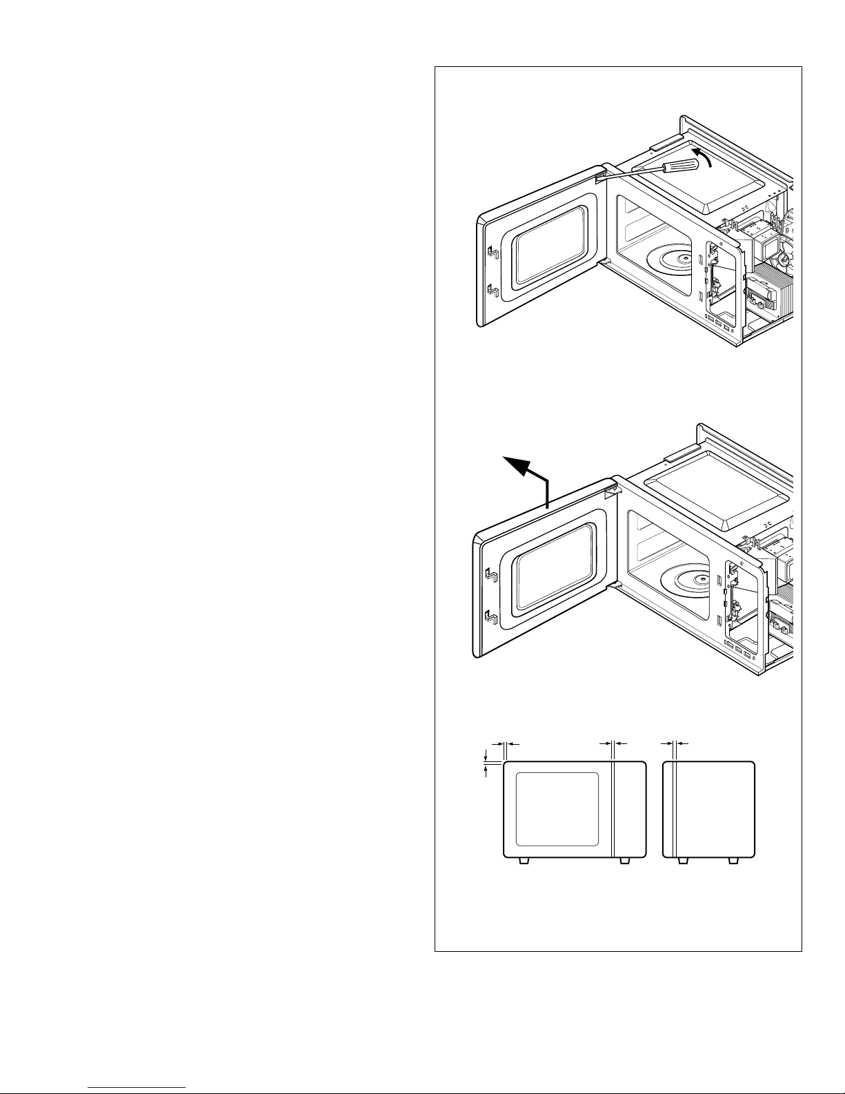
-15-
C. DOOR GROSS ASSEMBLY REMOVAL
(1) Open the door.
(2) Remove the choke cover very carefully with a flat-blade
screwdriver.
CAUTION : Be careful not to damage door seal plate by
screwdriver.
(3) Lift up and push the door.
NOTE:
1. After replacing the door, be sure to check that the primary
switch, monitor switch, and secondary switch operate
normally.
2. After replacing the door, check for microwave energy leakage
with a survey meter. Microwave energy must be below the
limit of 5 mW/cm.sq. (with a 275 ml water load)
3. When mounting the door assembly to the oven assembly, be
sure to adjust the door assembly parallel to the chassis. Also
adjust so the door has no play between the inner door surface
and oven frame assembly. If the door assembly is not
mounted properly, microwaves may leak from the clearance
between the door and the oven.
Remove choke cover
Remove Door
Figure 10
Page 17
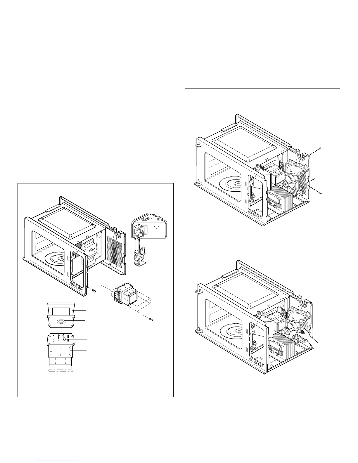
D. MAGNETRON REMOVAL
1) Disconnect the leadwire from the magnetron.
2) Carefully remove the mounting screws holding the
magnetron and the waveguide.
3) Remove the magnetron ASSEMBLY until the tube is clear
from the waveguide.
NOTE:
1. When removing the magnetron, make sure its dome
does not hit any adjacent parts, or it may be damaged.
2. When replacing the magnetron, be sure to install the
magnetron gasket in the correct position and be sure
that the gasket is in good condition.
3. After replacing the magnetron, check for microwave
leakage with a survey meter around the magnetron.
Microwave energy must be below the limit of 5 mW/cm2..
(With a 275 ml. water load).
Make sure that gasket is rigidly attached to the
magnetron. To prevent microwave leakage, tighten the
mounting screws properly, making sure there is no gap
between the waveguide and the magnetron.
E. SUCTION GUIDE MAIN ASSEMBLY
NOTE: To repair any of them, the Suction Guide Main ASS’Y
should be removed first.
1) Disconnect the wire lead from the capacitor and fan motor.
2) Remove three screws holding the Suction Guide Main
ASS’Y to oven cavity.
3) Pull out Suction Guide Main ASS’Y from the oven.
-16-
Magnetron
Air Duct
Waveguide
Magnetron
Gasket
Magnetron
Dome
Waveguide
Bracket
Figures 11
Pull out
Pull out suction guide main ASS Y
Screw
Remove screw
Figures 12
Page 18
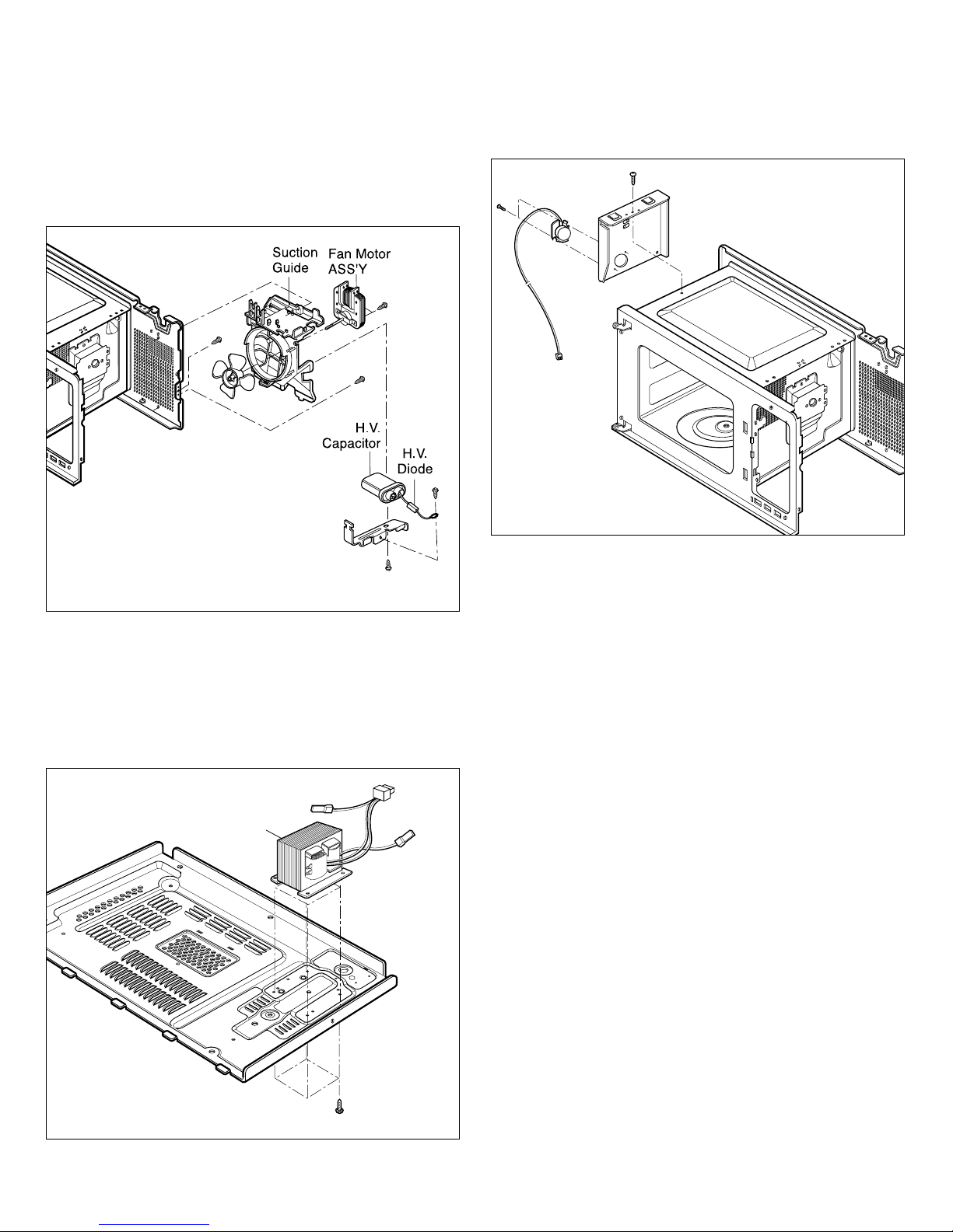
F. FAN MOTOR ASSEMBLY REMOVAL
NOTE: To repair any of them, the Suction Guide Main ASS’Y
should be removed first.
1) Disconnect the wire lead from fan motor.
2) Remove the fan.
3) Remove the two screws holding the fan motor assembly to
the suction guide ass’y.
G. HIGH VOLTAGE TRANSFORMER REMOVAL
1) Discharge the high voltage capacitor.
2) Disconnect the wire lead from magnetron, high voltage
transformer, and capacitor.
3) Remove the screw holding the high voltage transformer to
the base-plate.
H. REMOVING SENSOR
1) Disconnect the leadwire from PCB Assembly.
2) Remove a screw securing the sensor duct.
-17-
Figures 13
H.V.
Transformer
Figures 14
Figures 15
Page 19
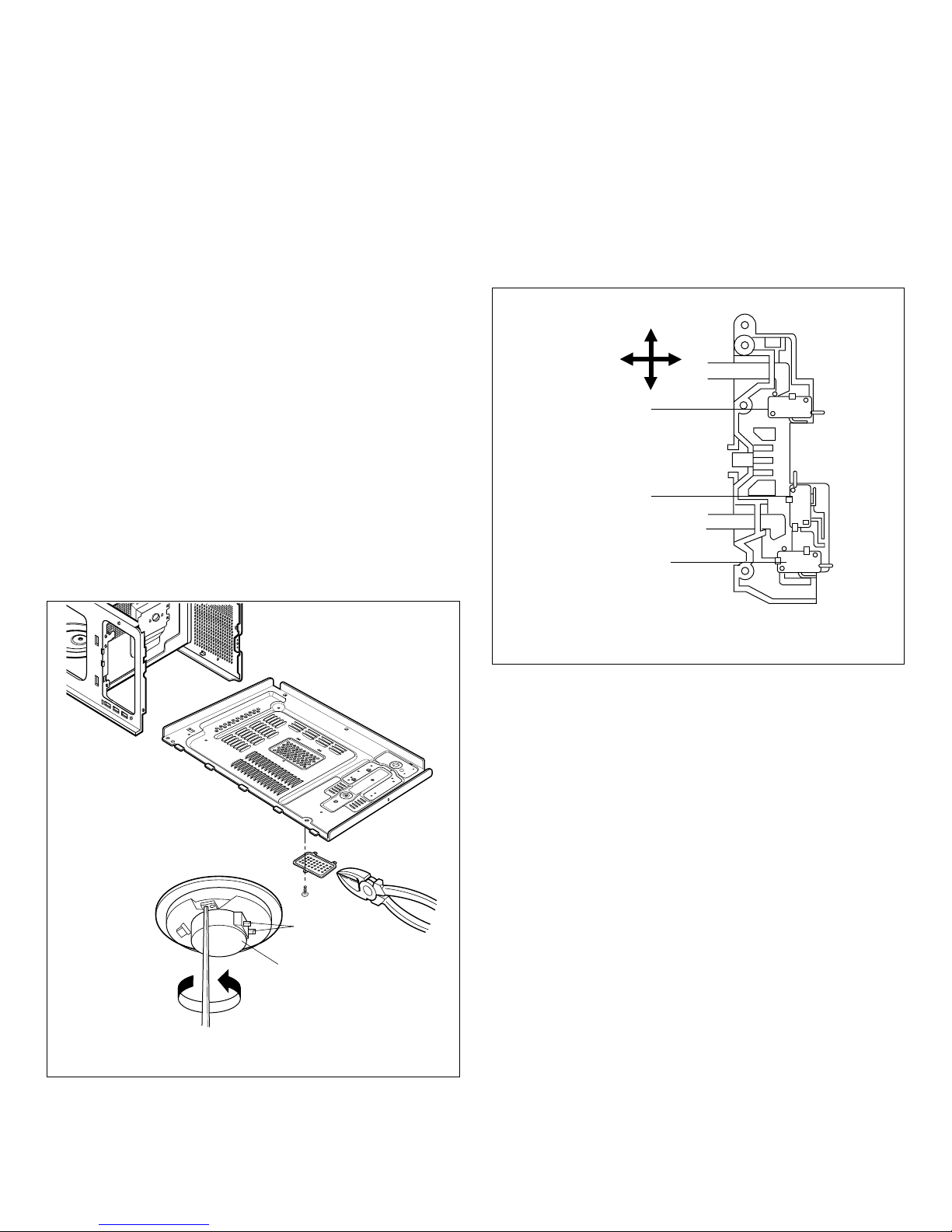
I. HIGH VOLTAGE CAPACITOR AND DIODE REMOVAL
1) Discharge the high voltage capacitor.
2) Disconnect the wire lead from the high voltage capacitor.
3) Remove the screw holding the high voltage capacitor
bracket.
J. REMOVING THE TURNTABLE MOTOR
1) Remove the glass turntable & the rotating ring ASS’Y by
hand.
2) Remove the turntable motor cover.
The turntable base cover is easily removed by pinching
the six parts with wire cutting pliers.
3) Disconnect the wire lead from the turntable motor
terminals.
4) Remove the screw securing the turntable motor to the
oven cavity assembly.
5) After repairing the motor, rotate the removed turntable
motor cover.
6) Fit the turntable motor cover's projecting part to the base
plate slit.
NOTE:
1. Remove the wire lead from the turntable motor VERY
CAREFULLY.
2. Be sure to grasp the connector, not the wires, when
removing.
K. INTERLOCK SYSTEM
(1) INTERLOCK MECHANISM
The door lock mechanism is a device which has been
specially designed to eliminate completely microwave
activity when the door is opened during cooking and thus
to prevent the danger resulting from the microwave
leakage.
(2) MOUNTING OF THE PRIMARY/MONITOR/
SECONDARY SWITCHES TO THE LATCH BOARD
(3) INSTALLATION AND ADJUSTMENT OF THE LATCH
BOARD TO THE OVEN ASSEMBLY
• Mount the latch board to the oven assembly.
• Adjust the latch board in the arrow direction so that oven
door will not have any play in it when the door is closed.
• Tighten the mounting screw.
• Check for play in the door by pushing the door
release button. Door movement should be less than
0.5 mm. (1/64 inch)
Don't push the door release button while making this
adjustment. Make sure that the latch moves smoothly after
adjustment is completed and that the screws are tight.
Make sure the primary, monitor, and secondary switches
operate properly by following the continuity test
procedure.
-18-
Wire Leads
Turntable Motor
Figures 16
PRIMARY
SWITCH
ADJUSTMENT
DIRECTION
MONITOR
SWITCH
SECONDARY
SWITCH
Figures 17
Page 20
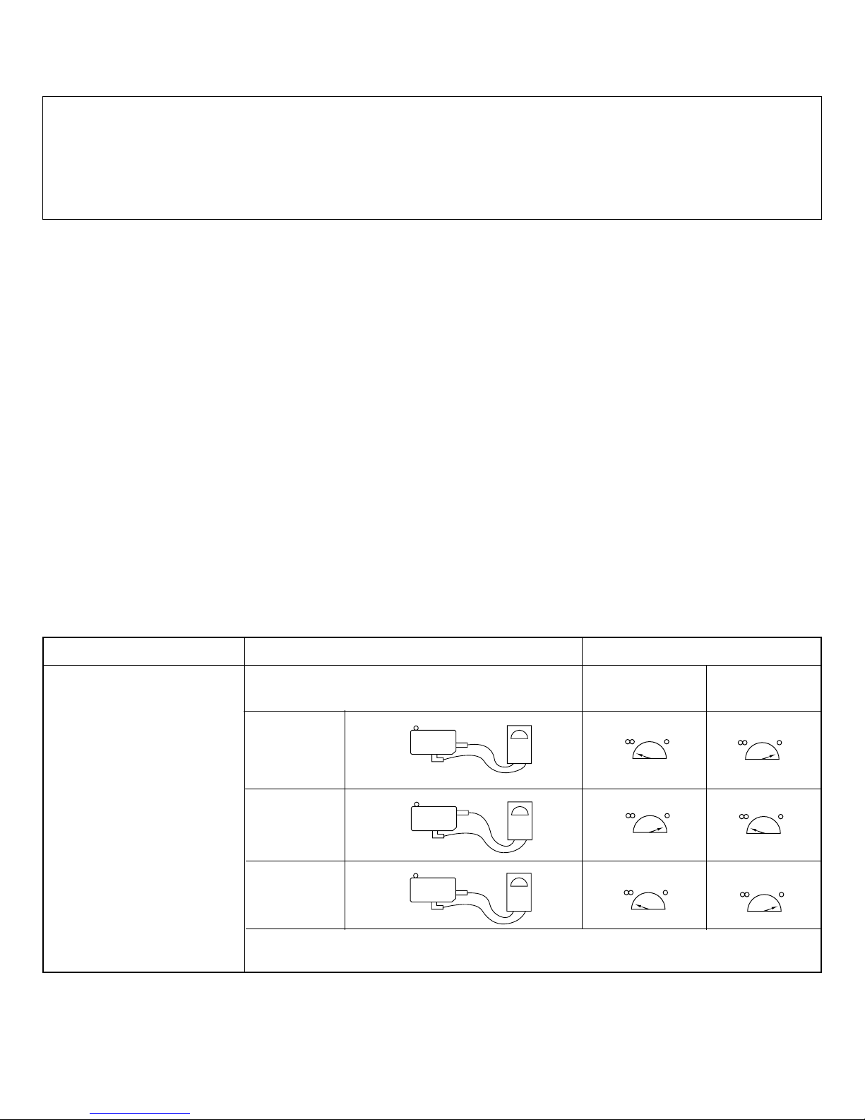
-19-
NO
COM
NC
COM
NO
COM
A. PRIMARY INTERLOCK SWITCH TEST
When the door release button is depressed slowly with
the door closed, an audible click should be heard at
the same time or successively at intervals. When the
button is released slowly, the latches should activate
the switches with an audible click.
If the latches do not activate the switches when the
door is closed, the switches should be a adjusted in
accordance with the adjustment procedure. Disconnect
the wire lead from the primary switch. Connect the
ohmmeter leads to the common (COM) and normally
open (NO) terminal of the switch. The meter should
indicate an open circuit in the door open condition.
When the door is closed, the meter should indicate a
closed circuit.
When the primary switch operation is abnormal, make
the necessary adjustment or replace the switch only
with the same type of switch.
B. SECONDARY INTERLOCK SWITCH TEST
Disconnect the wire lead from the secondary switch.
Connect the ohmmeter leads to the common (COM)
and normally open (NO) terminals of the switch. The
meter should indicate a open circuit in the door open
condition. When the door is closed, meter should
indicate an closed circuit. When the secondary switch
operation is abnormal, make the necessary adjustment
or replace the switch only with the same type of switch.
C. MONITOR SWITCH TEST
Disconnect the wire lead from the monitor switch.
Connect the ohmmeter leads to the common (COM)
and normally closed (NC) terminals of the switch. The
meter should indicate closed circuit in the door open
condition. When the door is closed, meter should
indicate an open circuit. When the monitor switch
operation is abnormal, replace with the same type of
switch.
NOTE: After repairing the door or the interlock system,
it is necessary to do this continuity test before
operating the oven.
10. INTERLOCK CONTINUITY TEST
WARNING : FOR CONTINUED PROTECTION AGAINST EXCESSIVE RADIATION
EMISSION, REPLACE ONLY WITH IDENTICAL REPLACEMENT PARTS.
TYPE NO. SZM-V 16-FA-63 OR VP-533A-OF FOR PRIMARY SWITCH
TYPE NO. SZM-V 16-FA-62 OR VP-532A-OF FOR MONITOR SWITCH
TYPE NO. SZM-V 16-FA-63 OR VP-533A-OF FOR SECONDARY SWITCH
COMPONENTS TEST PROCEDURE RESULTS
SWITCHES Check for continuity of the Door Door
(Wire leads removed) switch with an Ohm-meter open closed
Primary
Switch
Monitor
Switch
Secondary
Switch
NOTE : After checking for the continuity of switches, make sure that they are
connected correctly.
Page 21
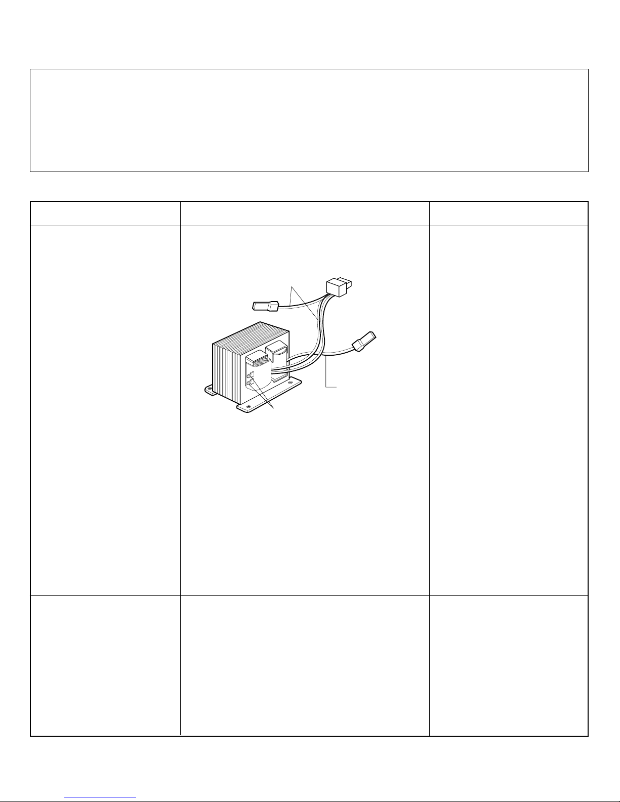
-20-
11. TEST AND CHECKOUT PROCEDURES, AND TROUBLESHOOTING
A. TEST PROCEDURES
CAUTIONS
1. DISCONNECT THE POWER SUPPLY CORD FROM THE OUTLET WHENEVER REMOVING THE OUTER CASE
FROM THE UNIT. PROCEED WITH THE TEST ONLY AFTER DISCHARGING THE HIGH VOLTAGE CAPACITOR
AND REMOVING THE WIRE LEADS FROM THE PRIMARY WINDING OF THE HIGH VOLTAGE
TRANSFORMER.
2. ALL OPERATIONAL CHECKS WITH MICROWAVE ENERGY MUST BE DONE WITH A LOAD (1 LITER OF
WATER IN CONTAINER) IN THE OVEN.
HIGH VOLTAGE
TRANSFORMER
(Wire leads removed)
MAGNETRON
(Wire leads removed)
Approx.: 0.4 ~ 0.6 ohm
Approx.: 70 ~ 100 ohm
Less than: 1 ohm
Normal: Infinite
Normal: Infinite
Normal: Less than 1 ohm
Normal: Infinite
PRIMARY
TERMINAL
SECONDARY
TERMINAL
FILAMENT
WINDING
TERMINAL
COMPONENTS TEST PROCEDURE RESULTS
1. Measure the resistance.
(Ohm-meter scale: Rx1 and Rx100)
• Primary winding
• Secondary winding
• Filament winding
2. Measure the resistance.
(Ohm-meter scale: Rx1000)
• Primary winding to ground
• Filament winding to ground
1. Measure the resistance.
(Ohm-meter scale: Rx1)
• Filament terminal
2. Measure the resistance.
(Ohm-meter scale: Rx1000)
• Filament to chassis
Page 22
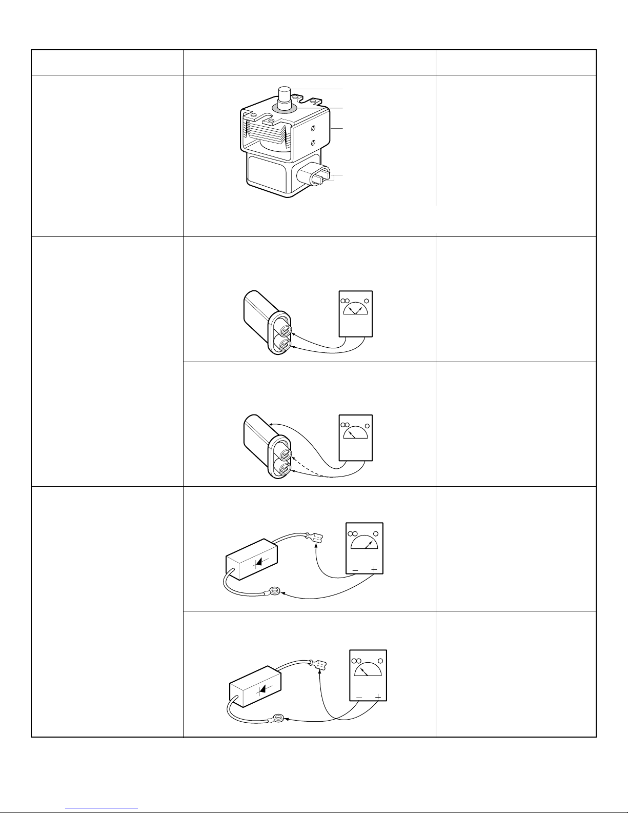
-21-
NOTE: When testing the magnetron, be sure to install the magnetron gasket in the
correct position and be sure that the gasket is in good condition.
Antenna
Gasket
Chassis
Filament
HIGH VOLTAGE
CAPACITOR
Measure the resistance.
(Ohm-meter scale: Rx1000)
• Terminal to terminal.
Normal: Momentarily indicates
several ohms, and
then gradually returns
to infinite.
Normal: Infinite.
Normal: Continuity.
Abnormal: Infinite.
Normal: Infinite.
Abnormal: Continuity.
Measure the resistance.
(Ohm-meter scale: Rx1000)
• Terminal to case.
Measure the continuity (Forward).
(Ohm-meter scale: Rx10000)
Measure the continuity (Reverse).
(Ohm-meter scale: Rx10000)
HIGH VOLTAGE
DIODE
NOTE :
Some inexpensive meters
may indicate infinite
resistance in both direction.
COMPONENTS TEST PROCEDURE RESULTS
Page 23
-22-
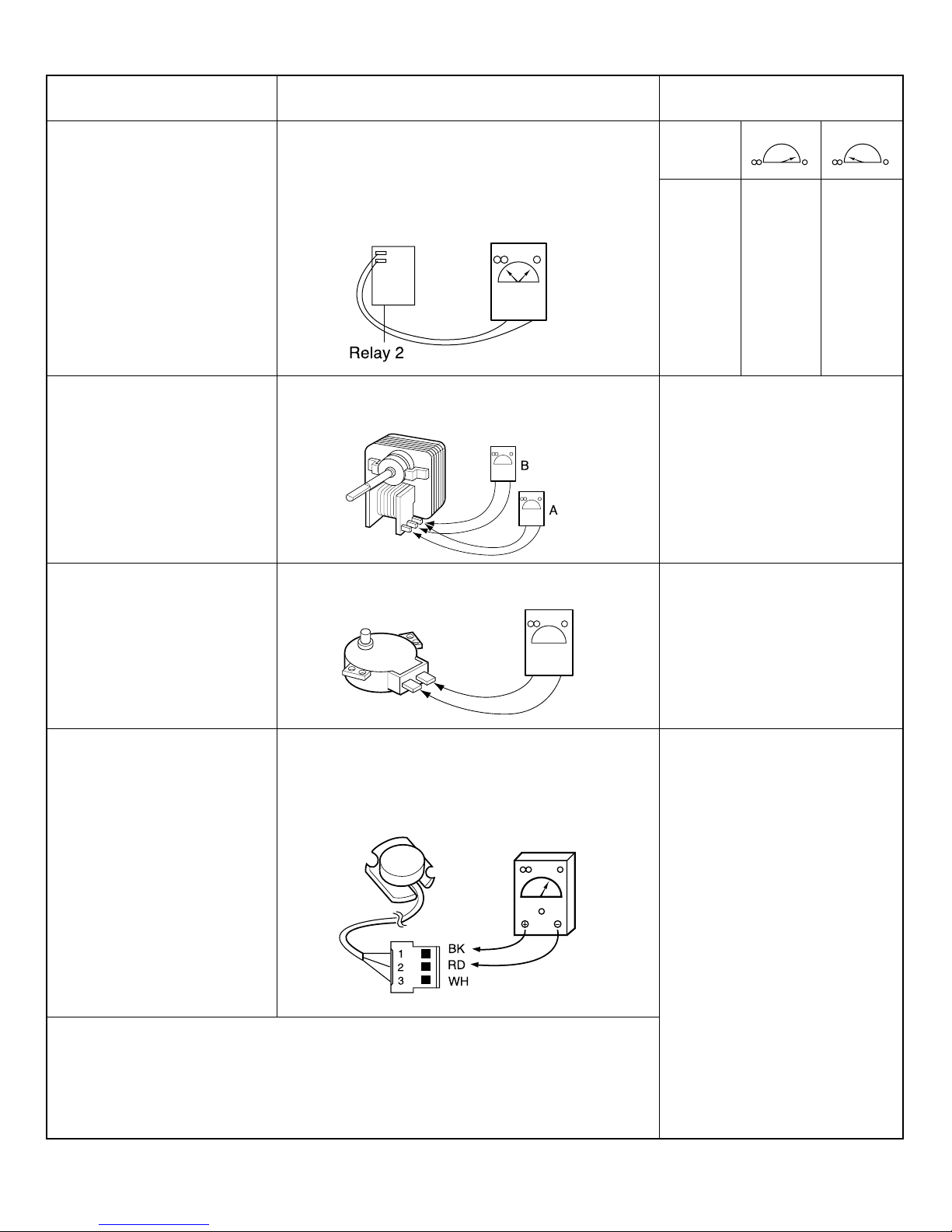
COMPONENTS TEST PROCEDURE RESULTS
RELAY 2
FAN MOTOR
(Wire leads removed)
TURNTABLE
MOTOR
(Wire leads removed)
SENSOR
Check for continuity of relay 2 with an ohmmeter.
(Remove wire leads from relay 2 and operate
the unit.)
NOTE : • A MICROWAVE LEAKAGE TEST MUST ALWAYS BE PERFORMED
WHEN THE UNIT IS SERVICED FOR ANY REASON.
• MAKE SURE THE WIRE LEADS ARE IN THE CORRECT POSITION.
• WHEN REMOVING THE WIRE LEADS FROM THE PARTS, BE SURE
TO GRASP THE CONNECTOR, NOT THE WIRES.
Measure the resistance.
(Ohm-meter scale: R x 1)
1) Disconnect sensor connector from micom
computer board.
2) Measure resistance terminal to terminal
(ohm meter scale: R X 1000)
Normal:
A: Approx. 95 ~ 120 ohm.
B: Approx. 10 ~ 25 ohm.
Abnormal: Infinite or several
ohm.
Normal: Approx.100~150 ohm
Abnormal: Infinite or several
ohm.
Normal: Approximately
BK - RD: 5.2 Kohm
RD - WH: 2.1 Kohm
BK - WH: 2.1 Kohm
Abnormal: Infinite or several.
* Sensor cooking condition
1. Oven should be plugged in at least
5 minutes before sensor cooking.
2. Room temperature should not
exceed 95°F .
3. Be sure the exterior of the cooking
container and the interior of the oven
are dry. Wipe each off with paper
towel.
4. The oven will not generate
microwave energy for the first 28
seconds of the sensor cooking cycle.
POWER
LEVEL
1
2
3
4
5
6
7
8
9
10
4 sec
6 sec
8 sec
10 sec
12 sec
14 sec
16 sec
18 sec
20 sec
22 sec
18 sec
16 sec
14 sec
12 sec
10 sec
8 sec
6 sec
4 sec
2 sec
0 sec
Measure the resistance.
(Ohm-meter scale: R x 1)
Page 24
B. CHECKOUT PROCEDURES
(1) CHECKOUT PROCEDURES FOR FUSE BLOWING
CAUTION: REPLACE BLOWN FUSE WITH 20 AMPERE FUSE.
NOTES:
- If the fuse is blown by an improper switch operation, replace the defective switches and the fuse at the same time.
After replacing the defective switches with new ones, make sure that they are correctly connected.
- Check for microwave energy leakage according to “1. ADJUSTMENT PROCEDURES” on page 3, when the
primary interlock, secondary interlock switches and/or the interlock monitor switches are adjusted or replaced.
-23-
PROBLEMS CAUSES
Fuse blows immediately after
the door is closed.
Improper operation of the primary interlock,
secondary interlock switches and/or the interlock
monitor switch.
Malfunction of the high voltage transformer; the high
voltage capacitor including the diode, the magnetron,
the blower motor or the circuit board.
Fuse blows immediately after
the door is opened.
Fuse blows when the door is closed and START key
is touched.
Page 25
-24-
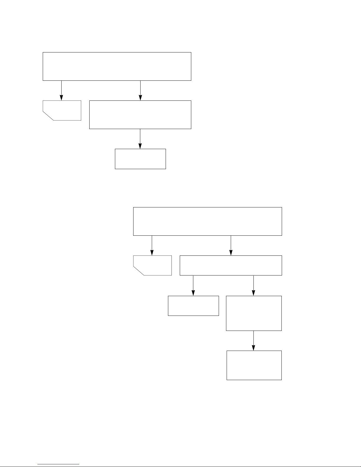
(2) CHECKOUT PROCEDURES FOR RELAY.
- PROBLEM (A) FAN motor and oven lamp turn on without touching
START key when the door is closed.
Remove the mate connector of I/O
CON from the circuit board does
the unit still operate?
Replace the
circuit board
NO
NO
YES
GOOD
- PROBLEM (B) FAN motor and oven lamp turn on When the door is
closed and START key is touched.
Check the interlock switches
Replace the
micro switches.
Defective
RELAY or poor
connection of
relay
Replace
RELAY or correct
the connection.
YES
NO
NO
YES
GOOD
Page 26

(3) CHECKOUT PROCEDURES FOR CIRCUIT BOARD
The following symptoms indicate a defective circuit
board.
(1) The start function fails to operate but the high
voltage Systems, the interlock switches, the door
sensing and the relay check good.
(2) The unit with a normal relay continuously operates.
(3) The buzzer does not sound or continues to sound.
(4) Some segments of one or more digits do not light up, or
they continue to light up, or segments light when they
should not.
(6) Wrong figures appear.
(7) The figures of all digits flicker.
(8) Some of the indicators do no light up.
(9) The clock does not keep time properly.
-25-
NOTE: A MICROWAVE ENERGY LEAKAGE TEST MUST ALWAYS BE PERFORMED WHEN THE UNIT IS
SERVICED FOR ANY REASON.
Page 27
-26-
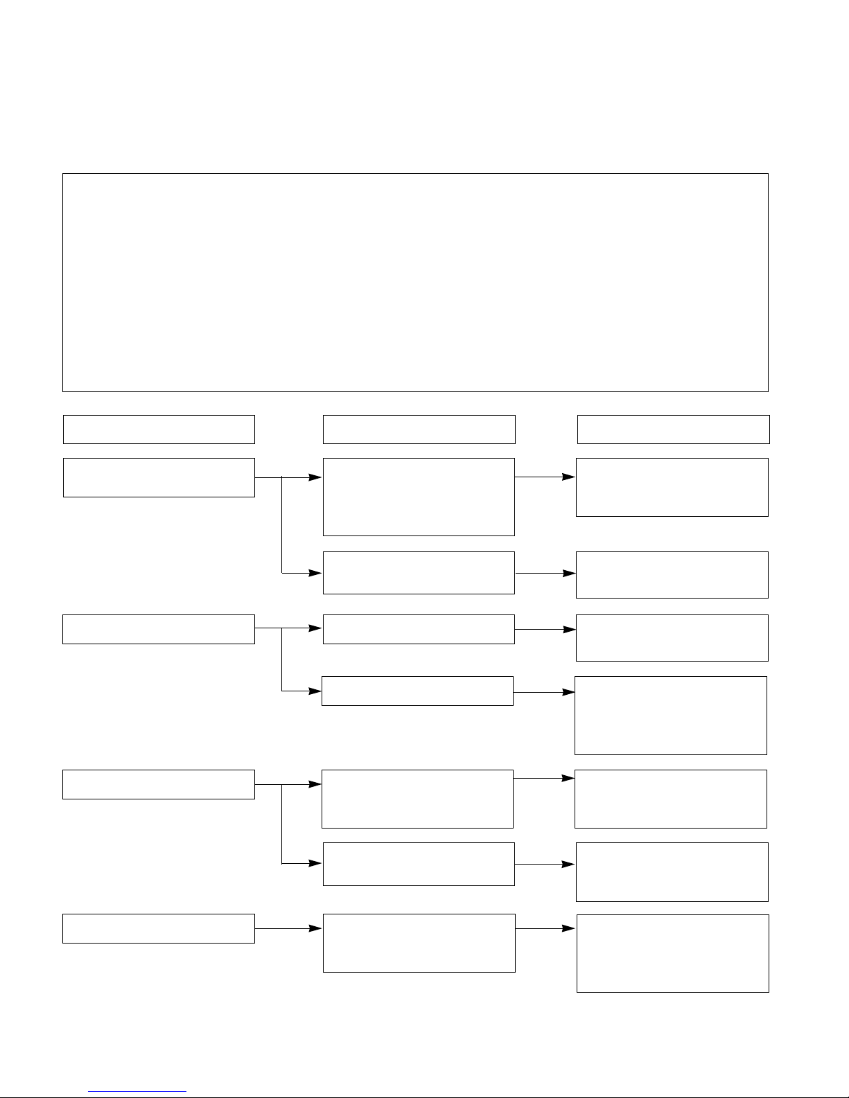
CONDITION
Microwave oven
does not work.
Inserting many plugs into one
outlet and using them at the
same time
(blown fuse or breaker)
Microwave oven plug is not
inserted tightly.
Output power is too low. Low AC input voltage.
Food temperature is too low.
Using metallic ware and
allowing it to touch the oven
wall.
Sparks occur.
Inconsistent intensity of
microwave by their
characteristics.
1. Use plastic wrap or lid.
2. Stir once or twice while
cooking soup, cocoa or
milk, etc.
Uneven cooking.
Ceramic ware trimmed in
gold or silver powder is used.
Avoid using other electrical
appliances when you use the
microwave oven.
Insert microwave oven plug
securely.
Use the microwave oven at
adequate line voltage.
This may not be a defect.
It is possible that the food
should be cooked for a
longer time period.
Do not use metallic ware for
cooking except where noted
in the cooking guide.
Do not use any type of
cookware with metallic
trimming.
CAUSE REMEDY
C. TROUBLE SHOOTING
CAUTIONS
1. Check grounding before checking for trouble.
2. Be careful of the high voltage circuit.
3. Discharge the high voltage capacitor.
4. When checking the continuity of the switches or of the high voltage transformer, disconnect one lead wire from these
parts and then check continuity with the AC plug removed. To do otherwise may result in a false reading or damage
to your meter.
5. Do not touch any part of the circuit on the PCB since static electric discharge may damage this control panel.
Always touch yourself to ground while working on this panel to discharge any static charge built up in your body.
(Micom model only)
WHEN YOU GET A COMPLAINT FROM YOUR CUSTOMER, EVALUATE THE COMPLAINT CAREFULLY. IF THE
FOLLOWING SYMPTOMS APPLY, PLEASE INSTRUCT THE CUSTOMER IN THE PROPER USE OF THE MICROWAVE
OVEN. THIS CAN ELIMINATE AN UNNECESSARY SERVICE CALL.
Page 28
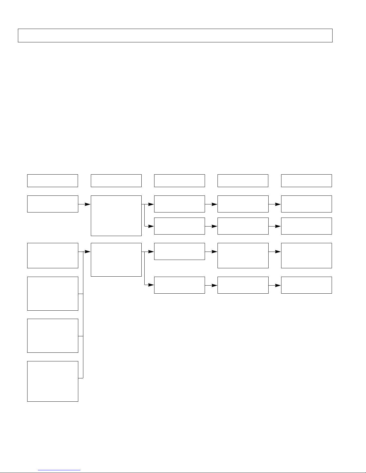
-27-
CONDITION CHECK RESULT CAUSE REMEDY
1. No input can be
programmed.
Continuity.
No continuity.
Defective PCB
assembly.
Replace PCB
assembly.
Check the connection between
membrane key
assembly and
PCB assembly.
Replace key
membrane
assembly and
check operation.
2. Some inputs
cannot be
programmed.
4. Random
programming
when touching
other pads.
5. Display is fixed
at some figure
and can not
accept any
input.
3. Display shows a
number or figure
different from one
touched.
Everything works
as specified.
Still have trouble.
Loose
connection.
Connect them
tightly.
Defective key
membrane
assembly.
Replace key
membrane
assembly.
Defective PCB
assembly.
Replace PCB
assembly.
(TROUBLE 1) The following visual conditions indicate a probable defective control circuit.
1. Incomplete segments.
• Segment missing.
• Partial segment missing.
• Digit flickering (NOTE: Slight flickering is normal.)
2. Colon does not turn on or blink.
3. A distinct change in the brightness of one or more numbers in display.
4. One or more digits in the display are not lighting.
5. Display indicates a number different from one touched, for example, key in 5 and 3 appears in the display.
6. Specific numbers (for example 7 or 9) will not display when key pad is touched.
7. Display does not count down with time blinking or up with clock operation.
8. Display obviously jumps in time while counting down.
9. Display counts down too fast while cooking.
10. Each indicator light does not turn on after setting cooking cycle.
11. Display time of day does not reappear when cooking is finished.
Page 29
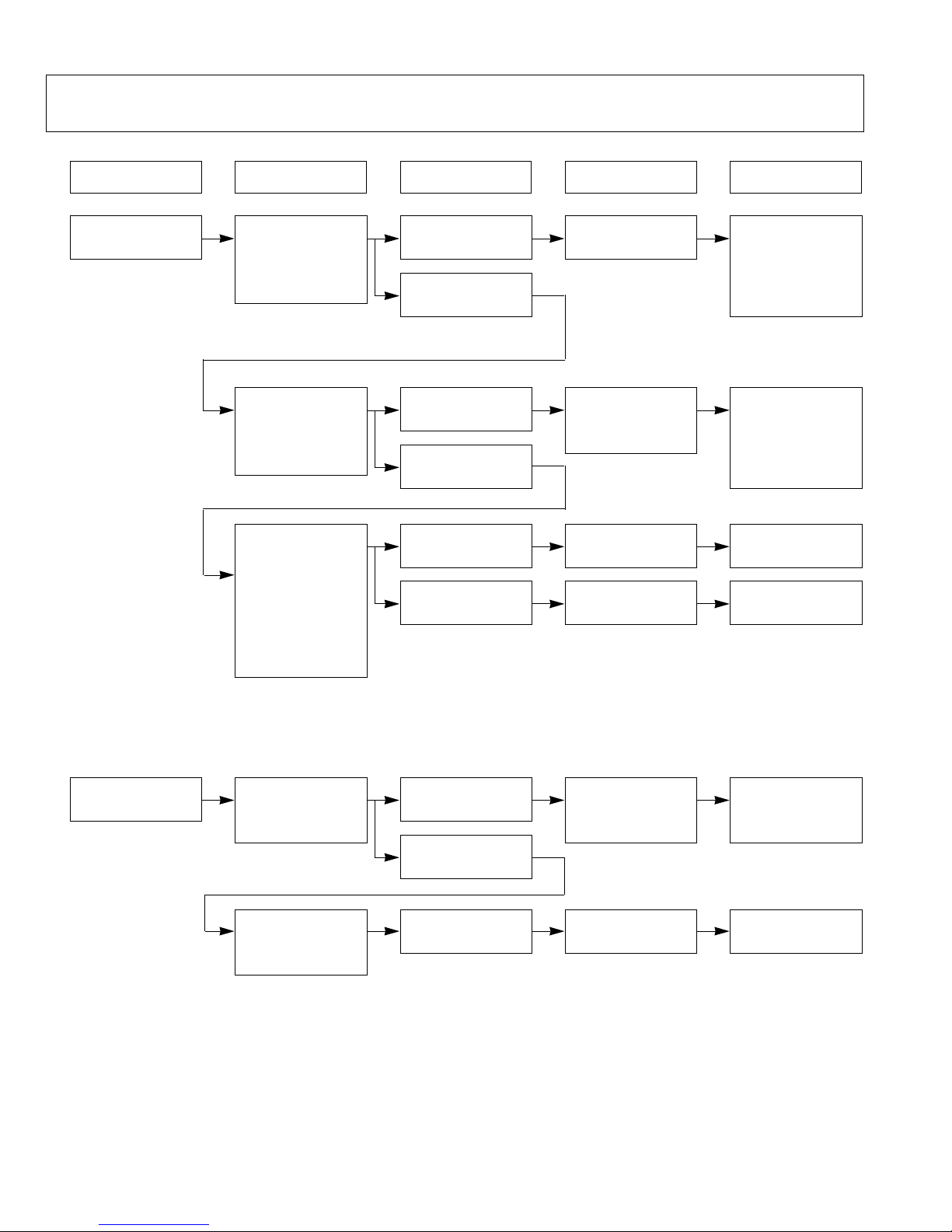
-28-
2. Fuse does not
blow.
No continuity.
Continuity.
No continuity.
Defective power
supply cord.
Replace power
supply cord.
Defective
thermostat.
Replace
thermostat.
Check continuity
of thermostat.
Check continuity
of power supply
cord.
CONDITION CHECK RESULT CAUSE REMEDY
(TROUBLE 2) Oven does not operate at all, Display window does not display any figures,
and no input is accepted.
1. Fuse blows.
Continuity.
No continuity.
Malfunction of the
monitor switch.
Replace fuse,
primary, monitor,
switches, and
RELAY(RY2) of
P.C.B Assembly.
Check continuity
of monitor
switch (with
door closed).
Continuity.
No continuity.
Shorted contact at
the primary switch.
Replace fuse,
primary, monitor,
switches, and
RELAY(RY2) of
P.C.B Assembly.
Check continuity
of primary
switch (with
door opened)
Normal.
Replace fuse
Fuse blows again
Defective high
voltage capacitor.
Replace high
voltage capacitor.
Disconnect one
side of the wire
lead connected
from transformer
to the high
voltage
capacitor and
operate the unit.
Defective high voltage transformer.
Replace high voltage transformer.
Page 30
-29-
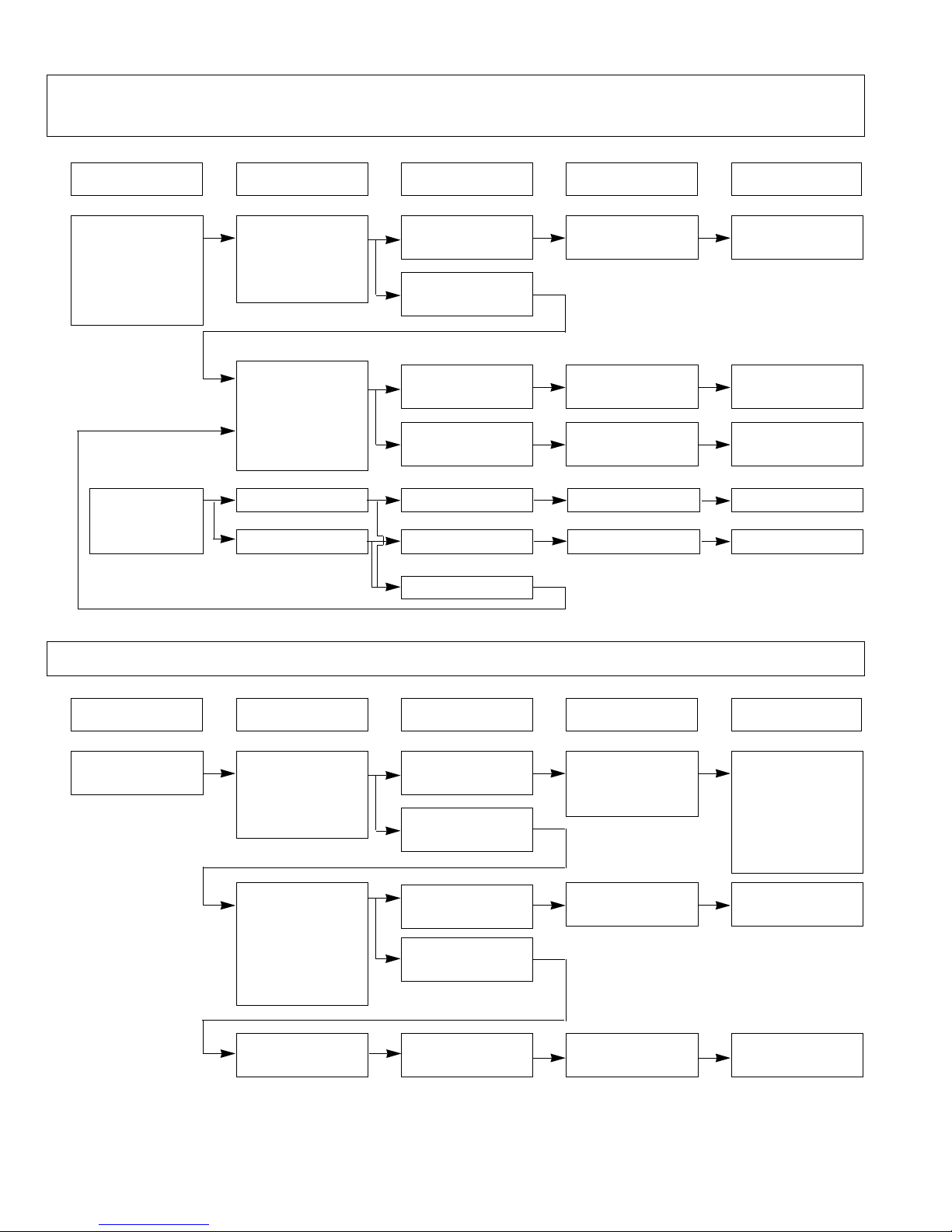
(TROUBLE 3) Display shows all figures set, but oven does not start cooking while desired
program times are set and START pad is touched.
(TROUBLE 4) Oven seems to be operation but little heat is produced in oven load.
1.Setting time
does not count
down when
touching START
pad.
2. Fan motor or
oven lamp do
not turn on.
No continuity.
Continuity.
Defective
secondary switch.
Replace
secondary switch.
Check continuity
of secondary
switch (with
door closed).
Check the connection between
CN1 connector
and PCB
assembly.
Continuity
No continuity
Abnormal
Abnormal
Normal
Defective fan motor.
Defective oven lamp.
Defective PCB
assembly.
Loose connection.
Output is low.
Lower than 90% of
rating voltage.
Normal.
Decrease in power
source voltage
with load.
Suggest customer
contact local
electric power
utility co. or
qualified
electrician.
Check the
power source
voltage.
Disconnect the
wire leads from
relay 2 and
check on and off
time with
multitester.
Measure the
output power.
Abnormal.
Abnormal.
Normal.
Defective PCB
assembly.
Defective
magnetron.
Replace PCB
assembly.
Replace
magnetron.
Replace PCB
assembly.
Connect them
tightly.
Replace fan motor.
Replace
oven lamp.
Check fan motor.
Check oven lamp.
CONDITION CHECK RESULT CAUSE REMEDY
CONDITION CHECK RESULT CAUSE REMEDY
NOTE: Simple test of power output-conducted by heating one liter water for one min. if available.
Minimum 8.5oC temperature rise is normal condition.
Page 31
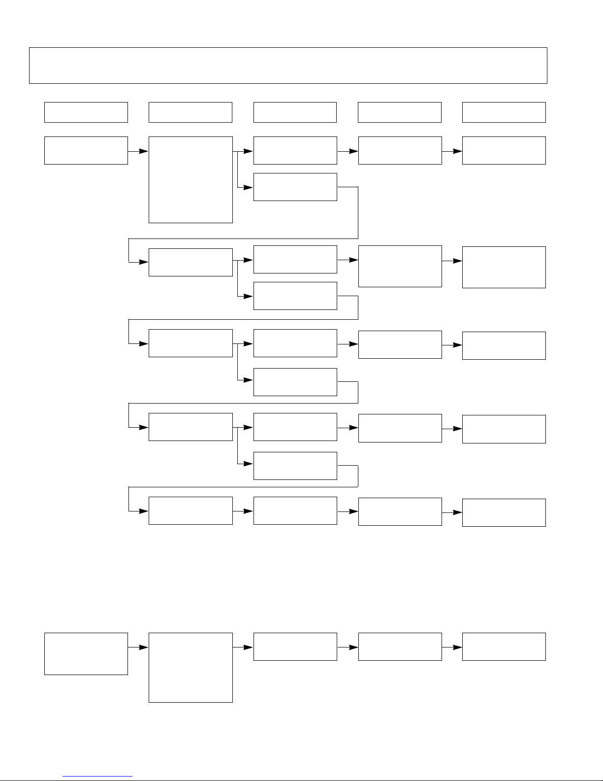
-30-
CONDITION CHECK RESULT CAUSE REMEDY
(TROUBLE 5) No microwave oscillation even though oven lamp and fan motor run.
(Display operates properly)
No microwave
oscillation.
No continuity.
Continuity.
Disconnect the
wire leads from
relay 2 and
check continuity
of relay2.
(Operate the unit)
Defective PCB
assembly
Defective high
voltage
transformer.
Replace PCB
assembly
Output is full power
when you set lower
power level.
Abnormal.
Disconnect the
wire leads from
relay 2 and check
continuity relay 2.
(Operate the unit)
Defective PCB
assembly
Replace PCB
assembly
Replace high
voltage
transformer.
Defective high
voltage capacitor.
Replace high
voltage capacitor.
Abnormal
normal
Check high voltage transformer
Abnormal
normal
Check high voltage capacitor.
Defective high
voltage diode.
Replace high
voltage diode.
Abnormal
normal
Check high voltage diode.
Defective
magnetron.
Replace
magnetron.
Abnormal
Check
Magnetron.
NOTE: • Make sure the wire leads correct position.
• When Removing the wire leads from the parts, be sure to grasp the connector, not the wires.
• When removing the magnetron, be sure to install the magnetron gasket in the correct position
and in good condition.
Page 32
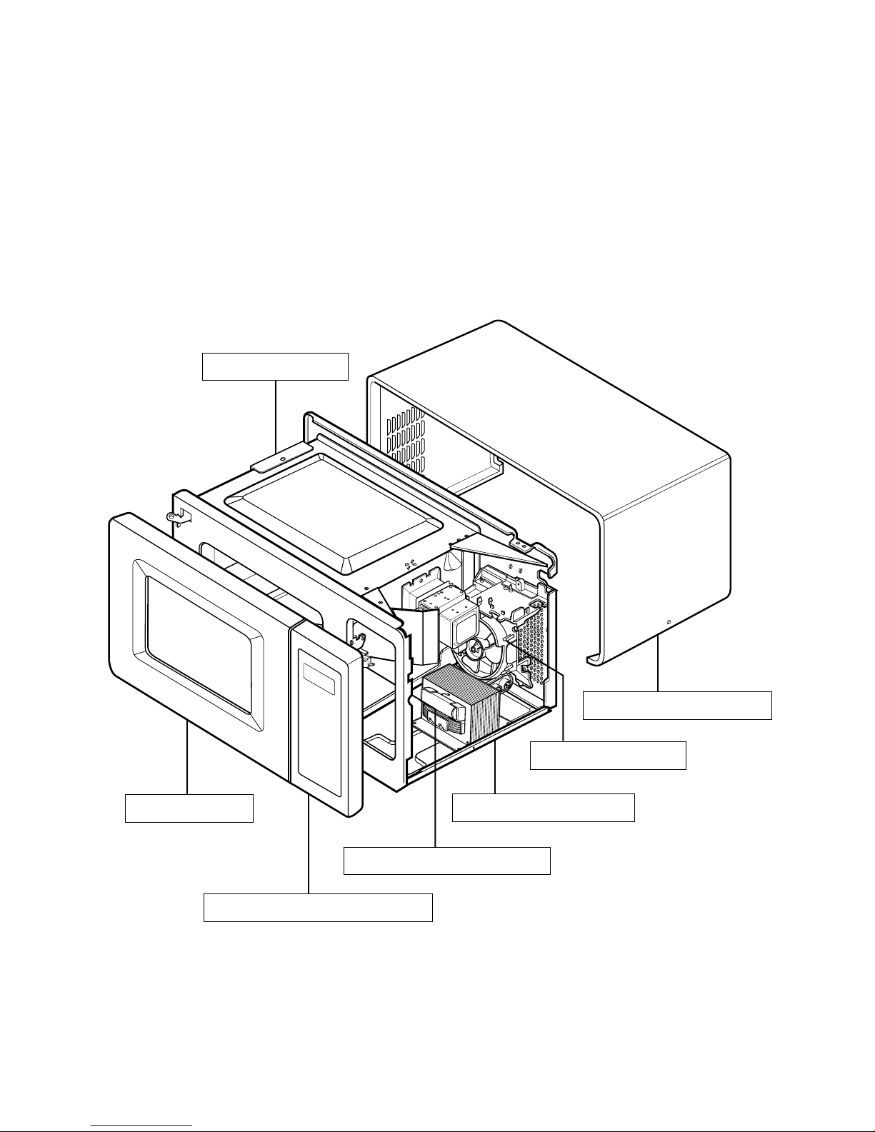
-31-
DOOR PARTS
CONTROL PANEL PARTS
BASE PLATE PARTS
OVEN CAVITY PARTS
LATCH BOARD PARTS
INTERIOR PARTS
SENSOR PARTS
#EV#
EXPLODED VIEW
INTRODUCTION
Model: 721.62252200 / 721.62252201
721.62259200 / 721.62259201
721.62253200 / 721.62253201
721.63263300 / 721.63263301
Page 33
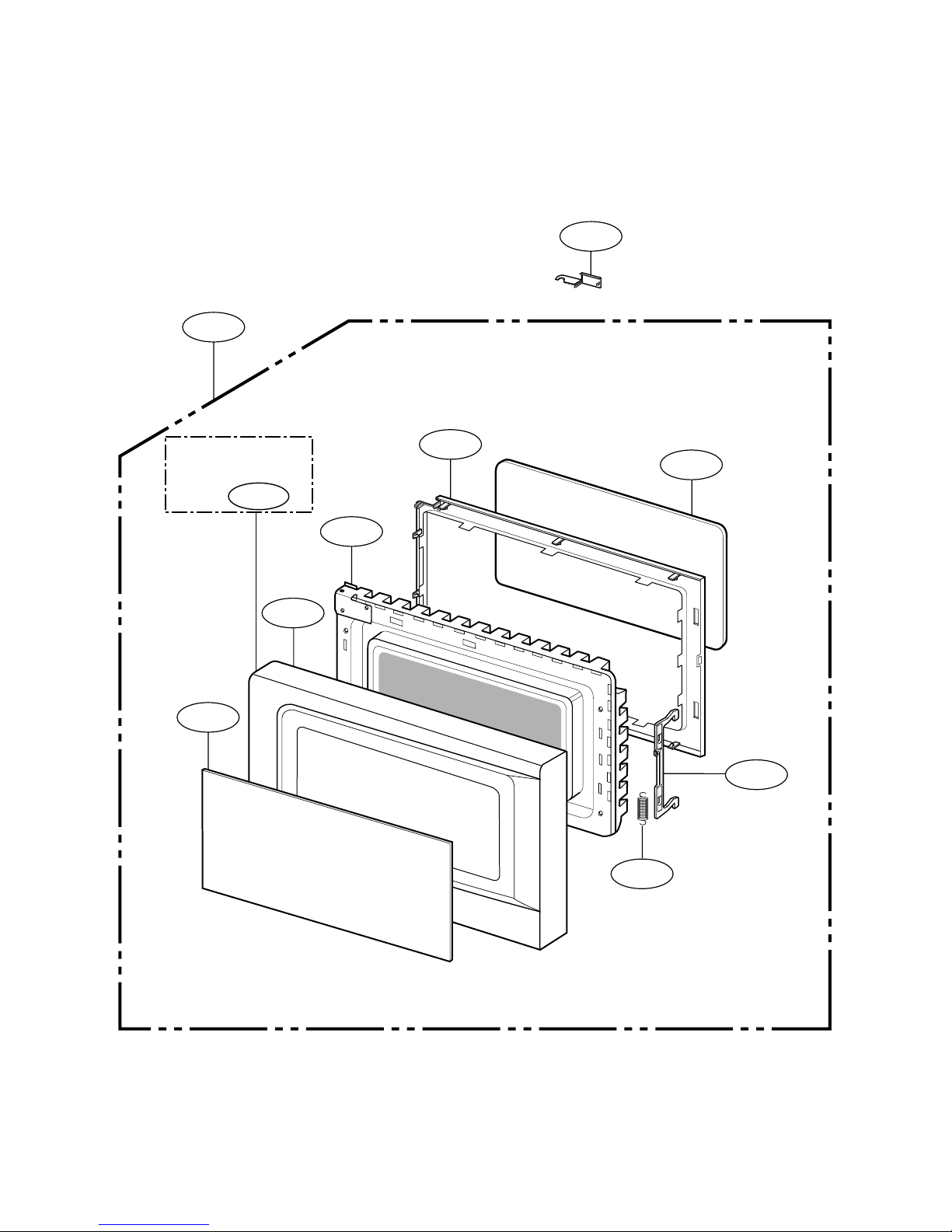
-32-
1004
1000
1001
1005
1003
1007
1006
1013
1002
1381
For Model 721.62253
721.63263
#EV#
DOOR PARTS
Page 34
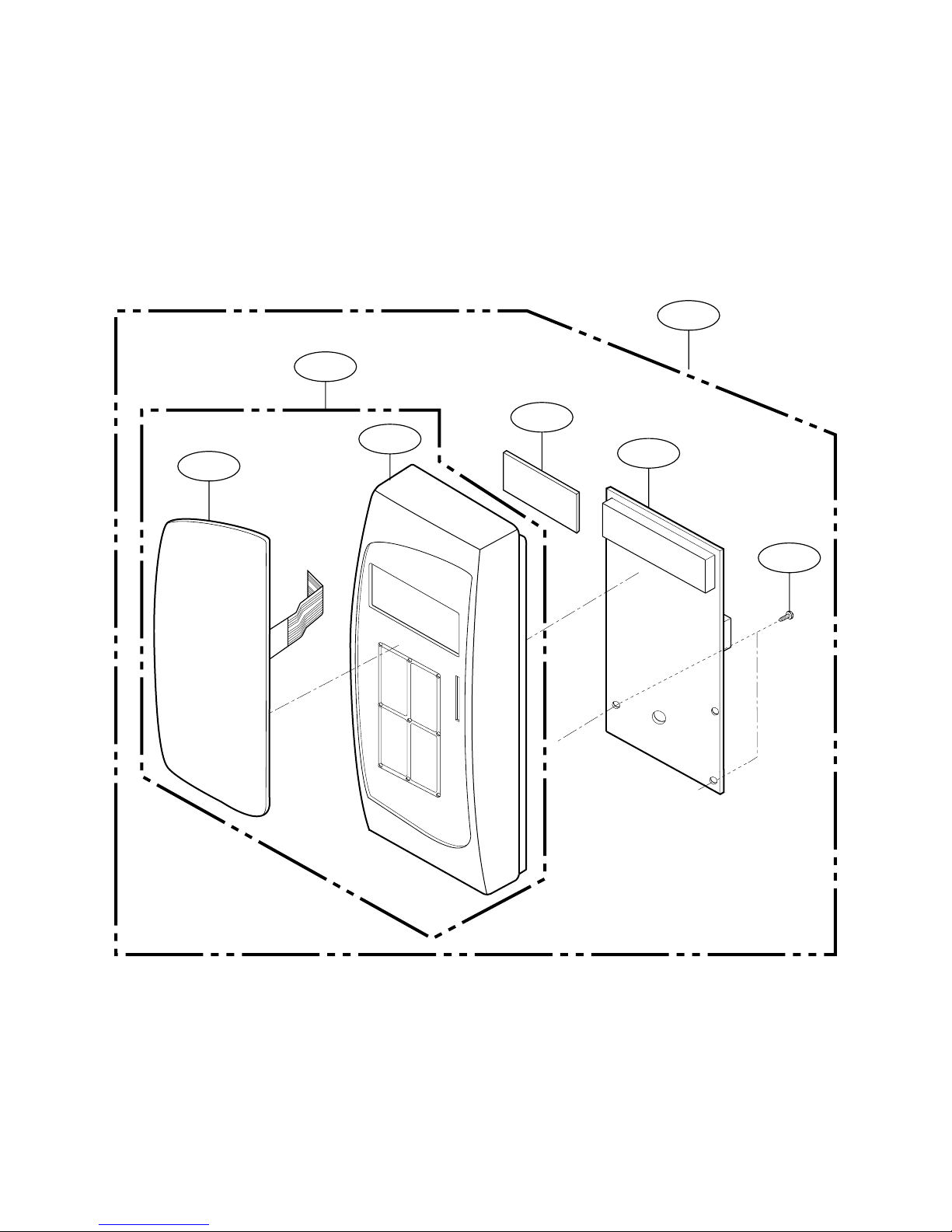
-33-
2000
2002
2001
2006
2004
2381
W106
#EV#
CONTROL PANEL PARTS
MODEL: 721.62259
721.62252
Page 35
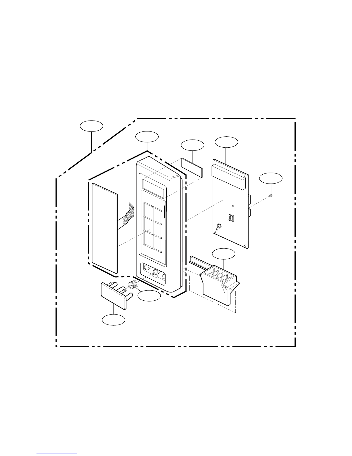
-34-
2004
2381
2001
2003
2005
2382
2006
W106
#EV#
CONTROL PANEL PARTS
MODEL: 721.62253
721.63263
Page 36
-35-
3009
3034
3003
W105
3002
W118
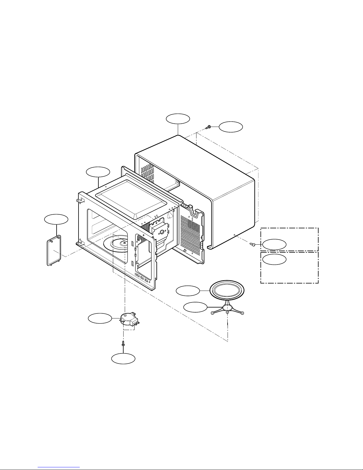
For Model 721.62252
721.63263
W107
W103
3001
3008
For Model 721.62259
721.62253
#EV#
OVEN CAVITY PARTS
Page 37
-36-
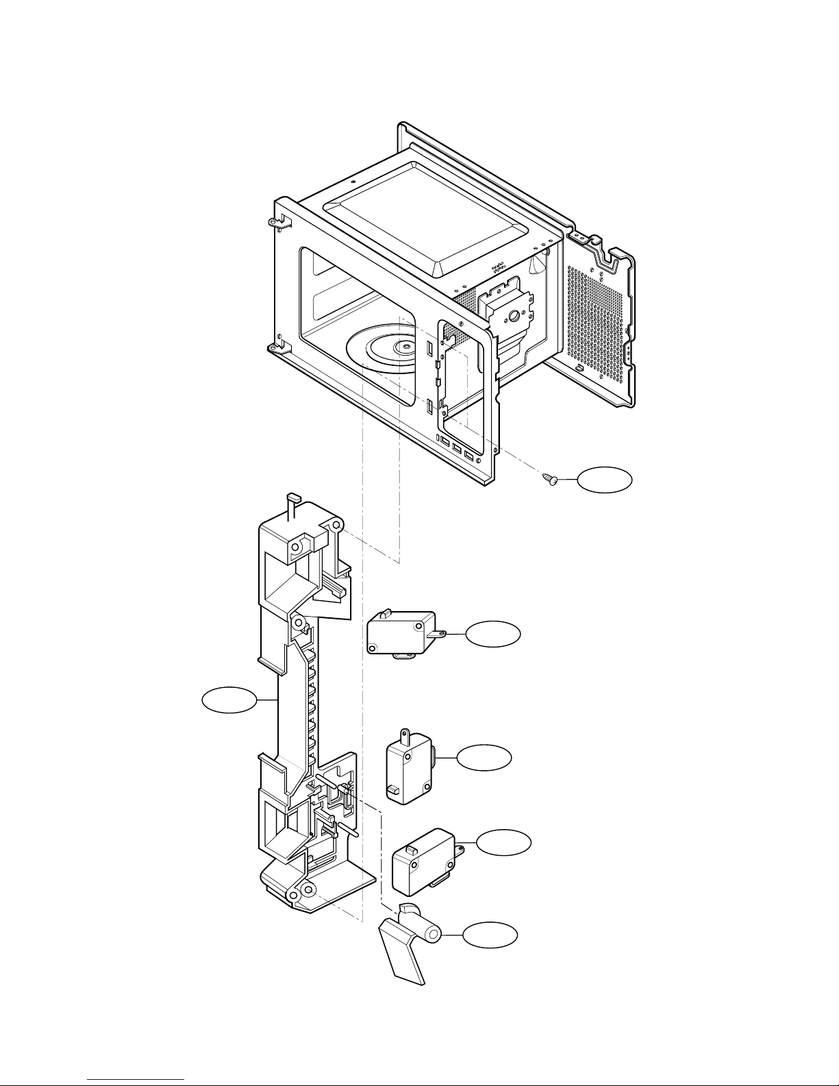
W102
4002
4000
4003
4002
4004
#EV#
LATCH BOARD PARTS
MODEL: 721.62259
721.62252
Page 38
-37-
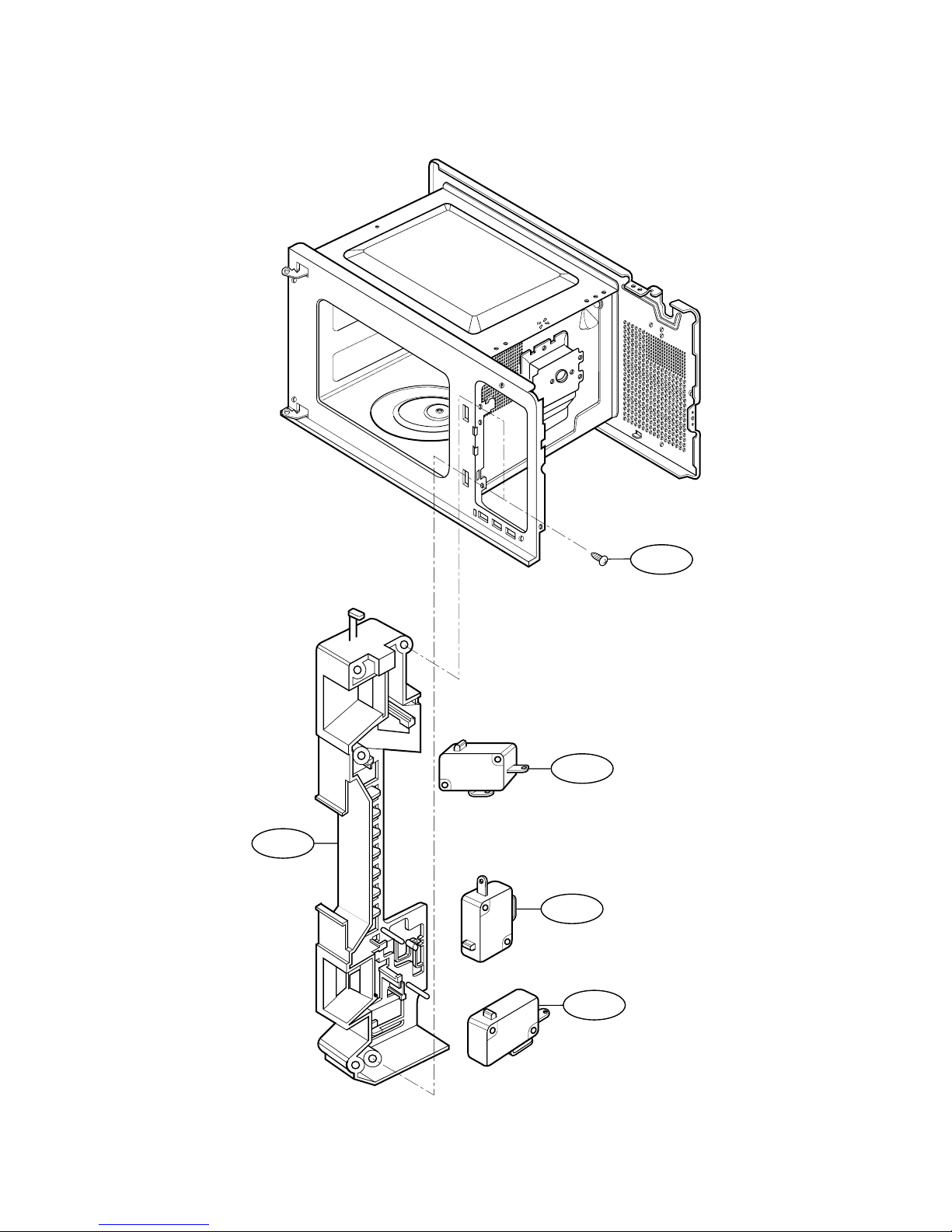
W102
4002
4003
4002
4000
#EV#
LATCH BOARD PARTS
MODEL: 721.62253
721.63263
Page 39
-38-
* Check the
Model No.
* Check the
Model No.
* Check the
Model No.
* Check the
Model No.
5014
W101
W101
9002
W101
W101
W208
W208
W109
W109
5010
5016
5012
5003
W110
5007
5009
5002
5000
5018
5015
5006
3006
9000
5040
W101
3007
5001
5005
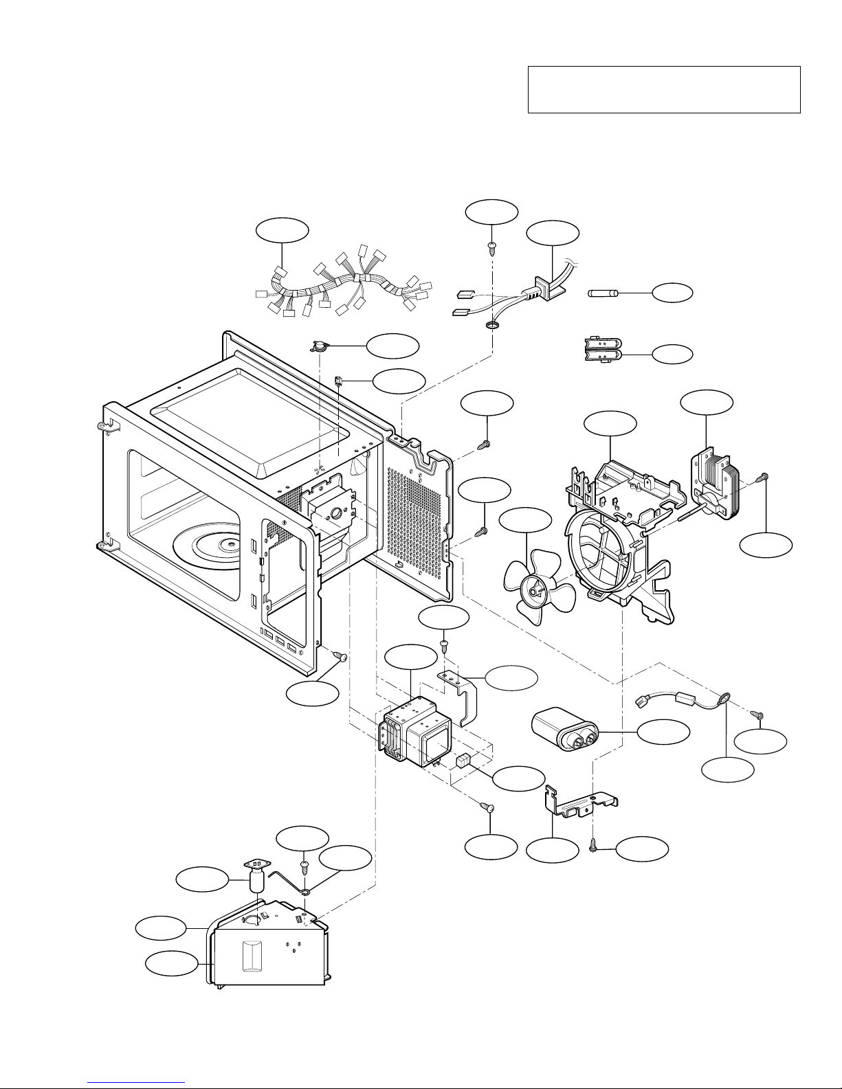
#EV#
INTERIOR PARTS (I)
Model: 721.62252200
721.62259200
721.62253200
721.63263300
Check the rating label of Model and order
SVC parts according to the Model No.
Page 40
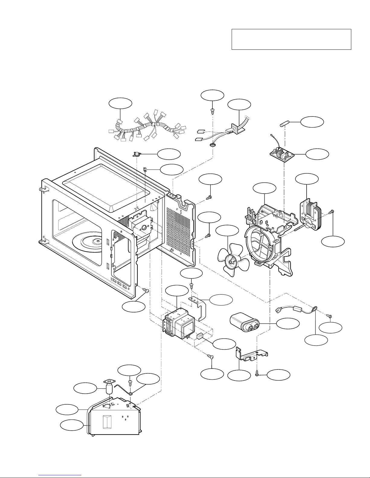
-39-
5001
* Check the
Model No.
* Check the
Model No.
* Check the
Model No.
* Check the
Model No.
5014
W101
W101
9002
W101
W101
W208
W208
W109
W109
5010
5016
5012
5003
5041
W110
5007
5009
5002
5000
5018
5015
5006
3006
9000
5040
W101
3007
#EV#
INTERIOR PARTS (II)
Model: 721.62252201
721.62259201
721.62253201
721.63263301
Check the rating label of Model and order
SVC parts according to the Model No.
Page 41
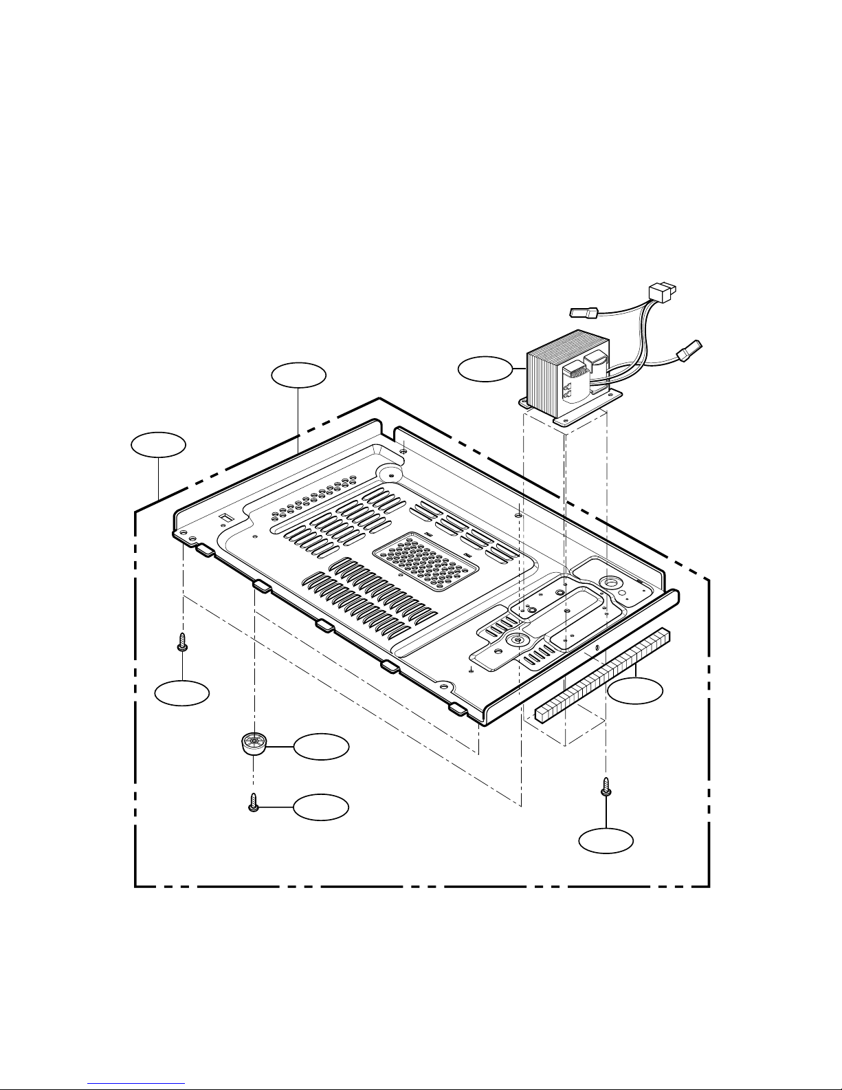
-40-
5008
6000
6001
W108
W101
W109
6002
9001
#EV#
BASE PLATE PARTS
Page 42
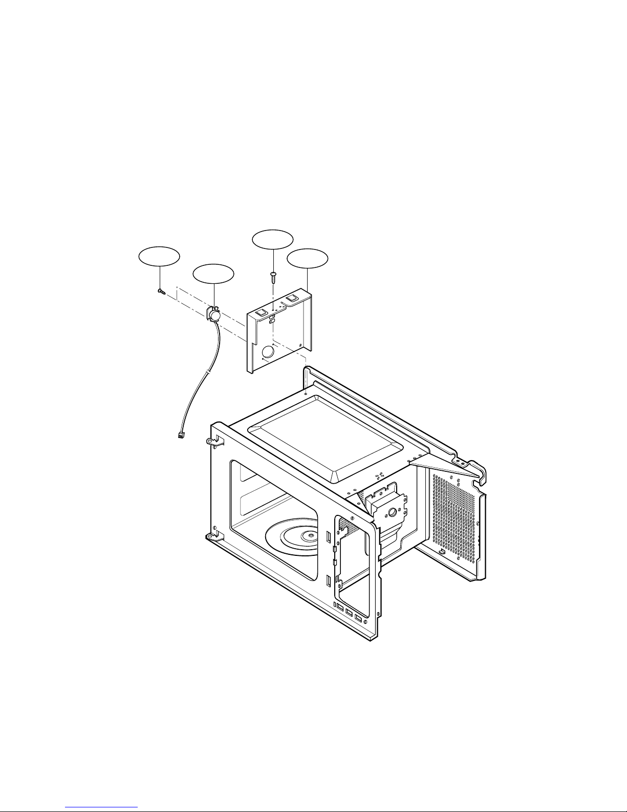
-41-
W108
5011
W136
5004
#EV#
SENSOR PARTS
Page 43

Printed in Korea
P/NO : 3828W5S5229
 Loading...