

Sears 721.37060700 User Manual

MODEL 721.37060700
DIVISION 20
BASIC FIELD MANUAL
FOR
UPRIGHT VACUUM CLEANER
MODEL 721.37060700
July , 2007

CONTENTS
MODEL 721.37060700
BEFORE SERVICING THE UNIT, READ THE “SAFETY PRECAUTIONS” IN THIS MANUAL.
MODEL 721.37060700
MECHANICAL SERVICE INFORMATION
TABLE OF CONTENTS
1. SAFETY PRECAUTION ................................................................................................................................................. 3
2. DESCRIPTION / SPECIFICATIONS …………............................................................................................................... 4
3. DISPLAY LED ………………………….…....................................................................................................................... 5
4. DISASSENBLY ……………………………..……….................................................................................................. 6 - 14
5. MAINTENANCE AND CARE ……………….……………...............................................................................................15
6. SCHEMATIC DIAGRAM ………….…………………......................................................................................................16
7. TROUBLE SHOOTING ………………………………………………………..……………….............................................17
8. EXPLODED VIEW ……………………………………………………......................................................................... 18-27
- 2 -

1. SAFETY PRECAUTIONS.
MODEL 721.37060700
BEFORE OPERATING VACUUM CLEANER, READ THIS SERVICE MANUAL
THOROUGHLY, AND OBSERVE EACH POINT CAREFULLY.
1. Pre Filter (Motor Safety Filter)
1) This filter is reusable.
2) Never use the vacuum cleaner without filter.
It may damage the motor.
3) For optimal performance, wash the Pre filter at least
once 6 months.
NOTE : Reusing of the motor filter.
• Never wash the filter in a washing machine or in a
dishwasher.
• Never use hot water for washing the filter.
• Reuse the filter after drying it completely in the shade
for a day.
• Do not dry near fire or direct sunray.
2. Exhaust filter
1) This filter is HEPA filter.
2) For clean air, this filter must be assembled.
3) For optimal performance ,replace the exhaust filter at
least once a year.
3. Avoid suction such materials as :
1) Liquid or wet dust :
Clogs the ventilation holes, reduces the suction power
significantly and harms the motor.
2) Inflammable liquids such as benzene, alcohol or
solvents.
3) Burning objects such as cigarette butts.
4) Bulky objects such as vinyl, paper etc.
5) Sharp objects such as needles, pins, metal,glass
particles etc.
4. Attachments
1) Crevice Tool:
: for cleaning any crevice, inside corners or window
frames. However, do not use the crevice tool more
than 20 minutes because it may cause harm to
the motor.
2) Dusting / Upholstery Tool
: for cleaning clothes curtains and cleaning stair.
3) Pet Handi Mate
: for cleaning the bare floor and carpet on the stair.
5. Close supervision is necessary when
this vacuum cleaner is used by or near
children.
Children’s carelessness may cause
damage to the cleaner or injure persons.
6. Air exhausted from the vacuum cleaner
is normally warm. But if extraordinarily
hot air is exhausted, check if the hose,
pre & exhaust filter is clogged or not.
7. Electric shock could occur if used
outdoors or on wet surfaces.
- 3 -
2. DESCRIPTION / SPECIFICATIONS
MODEL 721.37060700
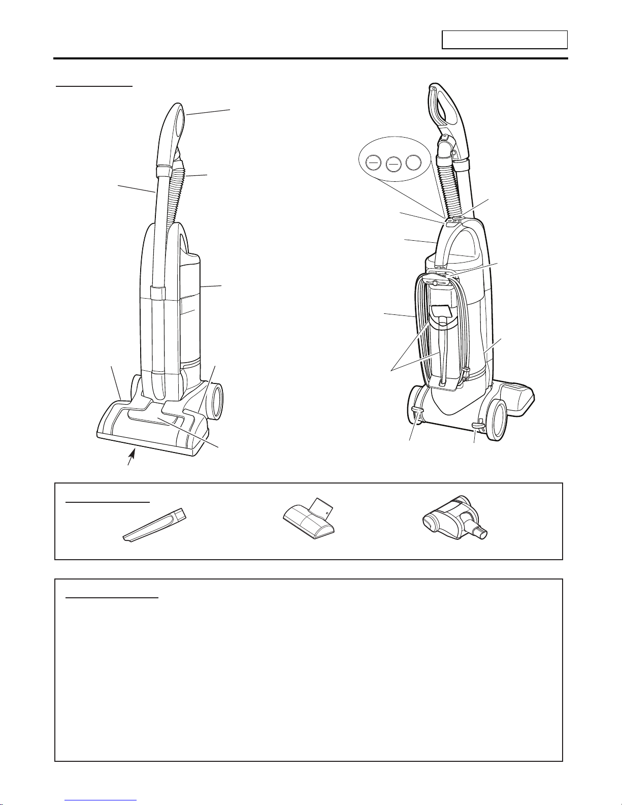
DESCRIPTION
Wand
Handle
LED Headlight
Crevice Tool
AMP : 12A
VOLTS : 120V
HERTZ : 60Hz
CORD LENGTH : 30 ft
HOSE LENGTH : 7 ft
WEIGHT : 15.23lb
DUST BIN CAPACITY : 2.2L
CLEANING WIDTH : 13.5 in
POWER CONTROL : MAIN - PUSH ON/OFF (BODY)
CARPET HEIGHT SELECTOR :
PUSH THE LEVER SELECTOR (HEAD)
AGITATOR ON /OFF :
PUSH CARPET/FLOOR (BODY)
Dusting / Upholstery Tool Pet Handi Mate
Agitator
Dust Tank
Hose
Wand
Power Level
Indicators
Carpet Height
Indicators
ATTACHMENTS
SPECIFICATIONS
- 4 -
Carry Handle
Dust Bin
Release Button
Handle Release
Pedal
Height
Adjustment
Pedal
30 ft. Cord
Quick
Release
Cord
Hanger
On-Board
Tool Storage
Handle Release
Button
Bottom
Plate
Release
Button
Floor
Carpet
ON
OFF
Hi
Med
Lo
Controls
3. DISPLAY LED
MODEL 721.37060700
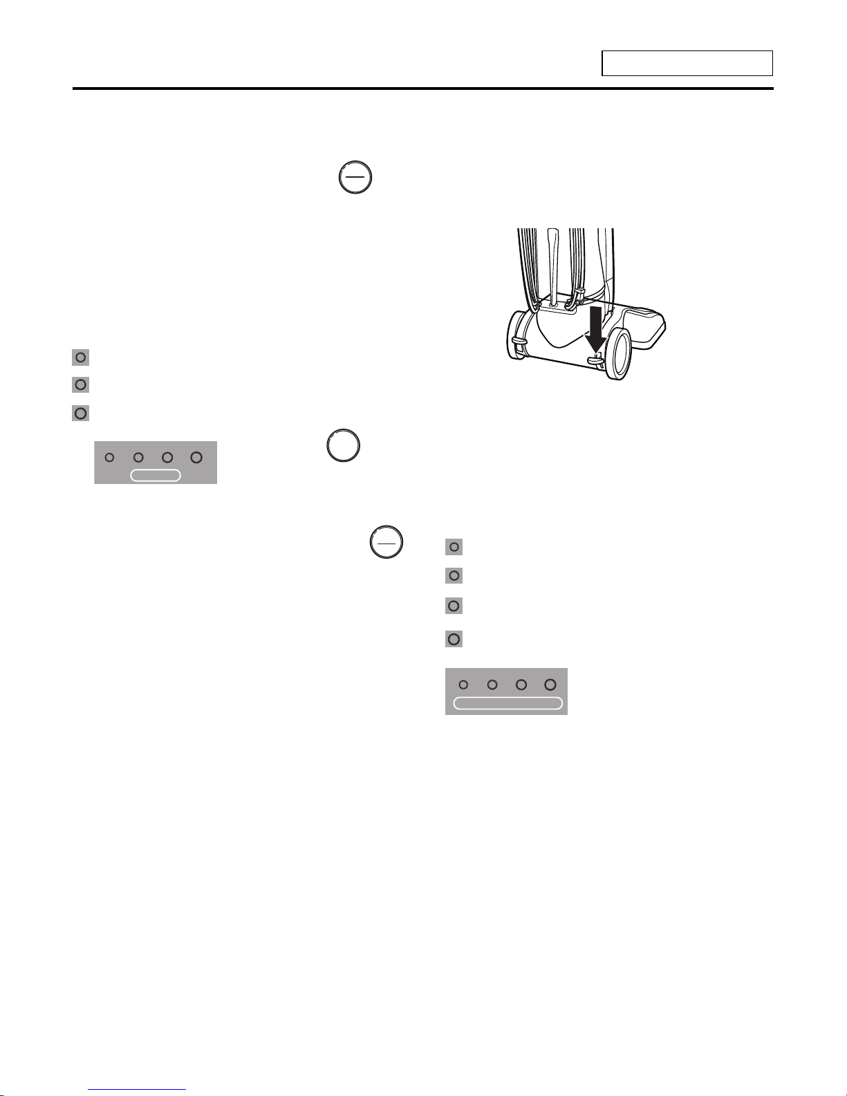
POWER ON/OFF ADJUSTING THE PILE HEIGHT
Press the right foot pedal to adjust the pile
height. Each press will lower or raise the agitator
one notch.
The LED indicator will light for each setting to
show what is selected.
Suggested pile height settings:
You may need to raise the height to make
some jobs easier, such as vacuuming scatter
rugs and longer pile rugs.
Recommended settings:
Attention: Special care is required when
vacuuming certain types of carpet or flooring.
Always check the carpet or floor covering
manufacturer’s recommended cleaning
instructions before vacuuming.
1. Plug the power cord into a proper outlet.
2. Press the ON/OFF button.
The Power indicator will light and
the main motor will run.
POWER LEVEL SELECTOR
1. Press the power button to select the power
level. Pressing the button repeatedly will
cycle through the power levels.
AGITATOR ON/OFF
4. For bare floors, press the Carpet/Floor
button to turn off the agitator.
NOTE: The agitator will not run with the handle
in the upright position.
ON
OFF
Lo
Hi
Med
Floor
Carpet
XLO very low pile, bare floors
L short to medium pile
M medium to long pile
H shag carpet, long pile, scatter rugs
HEIGHT ADJUSTMENT
- 5 -
When vacuuming, if the agitator is not running
at full speed due to an obstruction, in the agitator
area, the agitator "ON/OFF" LED will begin a
series of three flashes followed by a pause.
To correct problem: Turn off and unplug vacuum
cleaner, then remove obstruction from agitator.
Recommended settings:
Lo
: drapes, hard surfaces
Med
: furniture, upholstery, area rugs
Hi
: shag carpet, long pile, etc.
POWER
4. DISASSEMBLY
MODEL 721.37060700
NOTE: Before attempting to service or adjust any part of the vacuum cleaner, disconnect the
electrical power supply cord from the wall outlet.
Almost all of the parts of this vacuum cleaner
can be disassembled with a screw driver and
each connecting component easily fits together.
• Disassemble one by one referring to the
exploded view.
• If possible, do not disassemble except for the
necessary parts. It is not necessary to
disassemble the parts that are not detailed in
the exploded view.
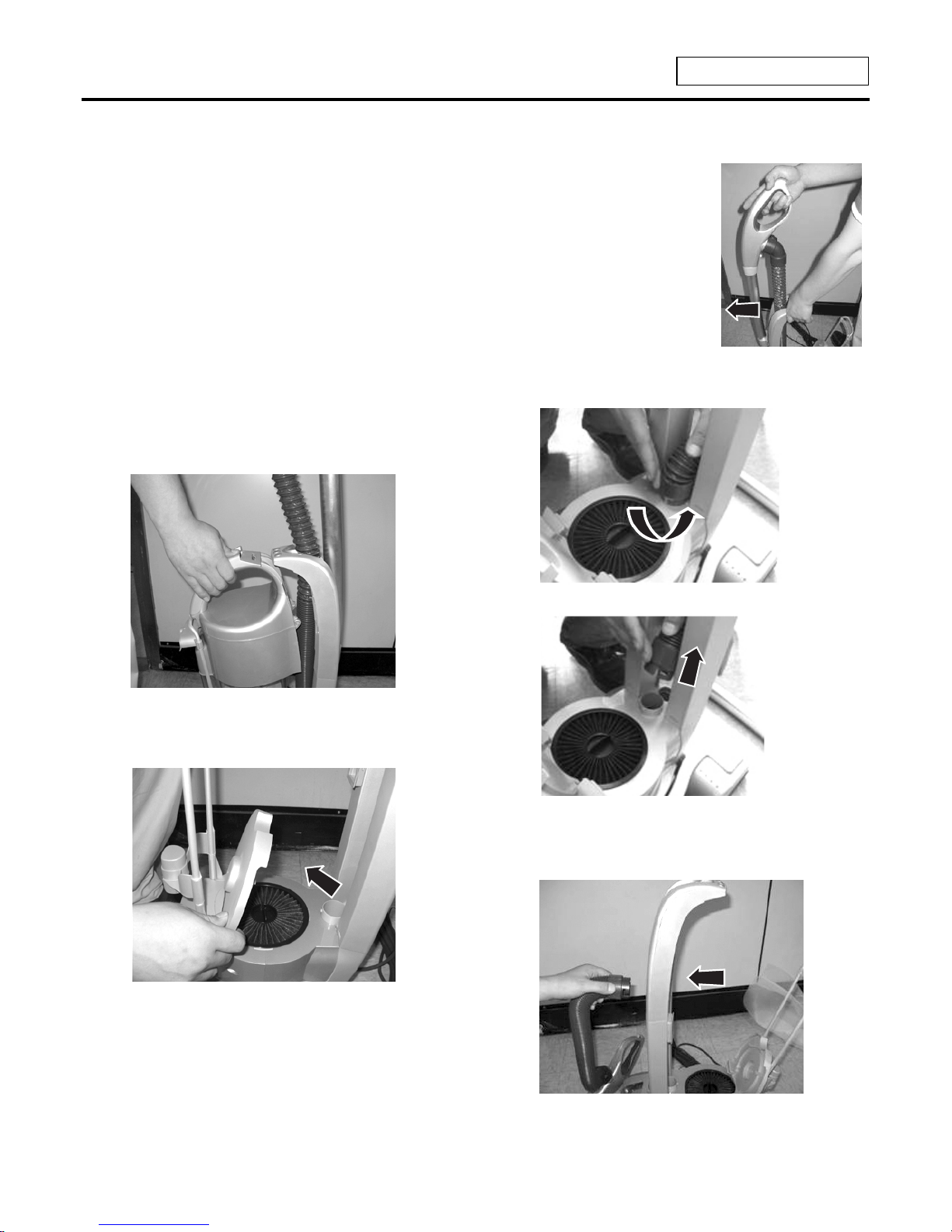
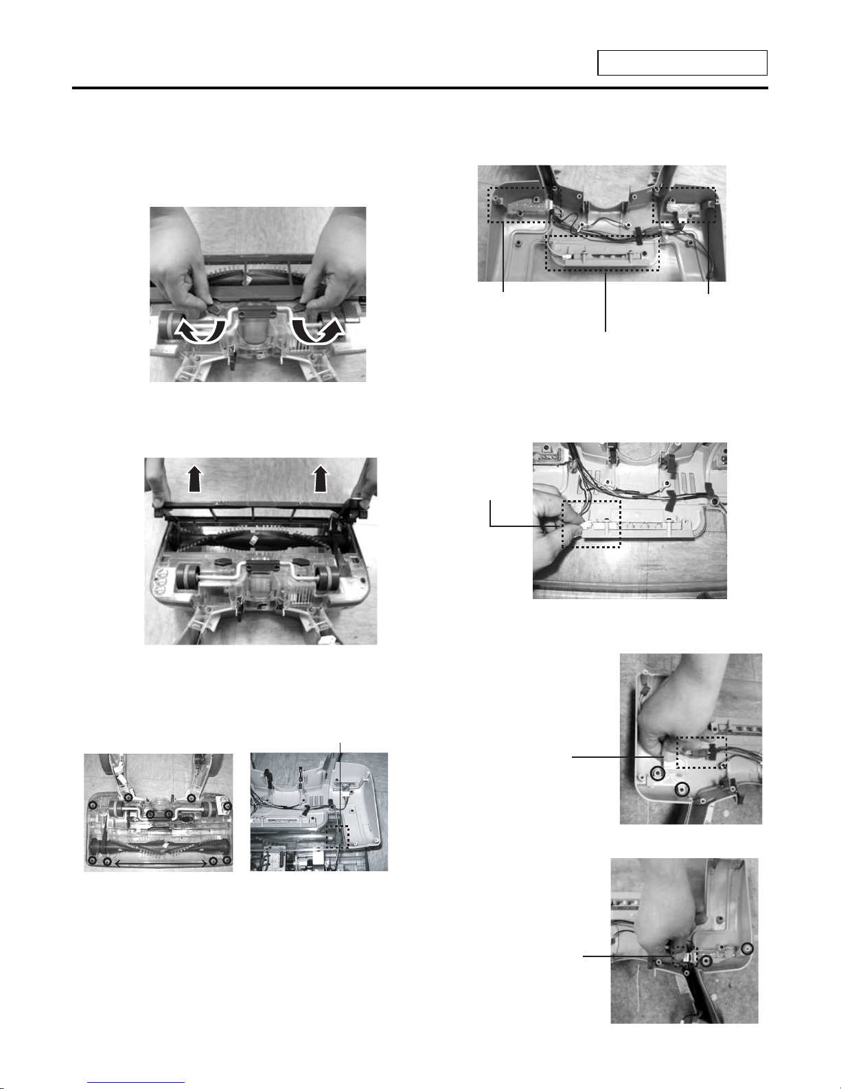
1. Head Assembly Replacement
1) Remove the dust bin as shown below.
2) Raise the HEPA Filter cover.
3) Press the wand release
button on the carry
handle and tilt the wand
handle forward.
Lift the wand out and up.
4) Remove the hose as shown below.
5) Remove the hose through the body at the
location shown.
- 6 -
4. DISASSEMBLY
- 7 -
MODEL 721.37060700
6) Press the left foot pedal and turn vacuum
cleaner over, push the latch on the Head to
the right and then the hose can be removed.
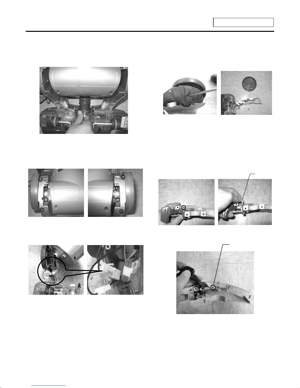
7) Remove the 4 screws on each side fastening
the Body and Head and then remove the 2
plate covers.
8) Remove the Head Assembly by removing the
three connectors as shown below.
9) To reinstall the Head Assembly reverse the
steps above.
2. Wheel Assembly replacement
1) Remove the C clip by using a straight
screwdriver and remove Wheel Assembly.
2) To reinstall the Wheel Assembly reverse the
steps above.
3. Lever Release replacement.
1) Remove the 1 screw and pull the shaft.
2) Lift lever from holder and release spring.
3) To reinstall the Lever Release reverse the
steps above.
Spring
Shaft
4. DISASSEMBLY
MODEL 721.37060700
4. Head Cover replacement.
1) Rotate the two cover retainers to unlock the
agitator cover.
2) Press in on the two tabs and rotate the agitator
cover up and off.
3) Remove the 10 screws and disconnect
receptacle with 3 pins and then disassemble
the Head Cover Assembly.
Note : Placement of small screws 3 x 8.
4) To reinstall the Head Cover reverse the steps
above.
5. PCB ASSEMBLY DISPLAY
REPLACEMENT
1> LED PCB Assembly Display replacement.
1) Remove the 1 screw and remove the
connector as shown.
2> Power PCB Assembly Display replacement
1) Remove the 2 screws
and remove the
connector as shown.
3> Height Adjustment PCB Assembly Display
replacement
1) Remove the 2
screws and remove
the connector as
shown.
Power LED PCB
Assembly
LED PCB
Assembly
Height Adjustment
LED PCB Assembly
Connector
Connector
Connector
Connector
- 8 -
MODEL 721.37060700
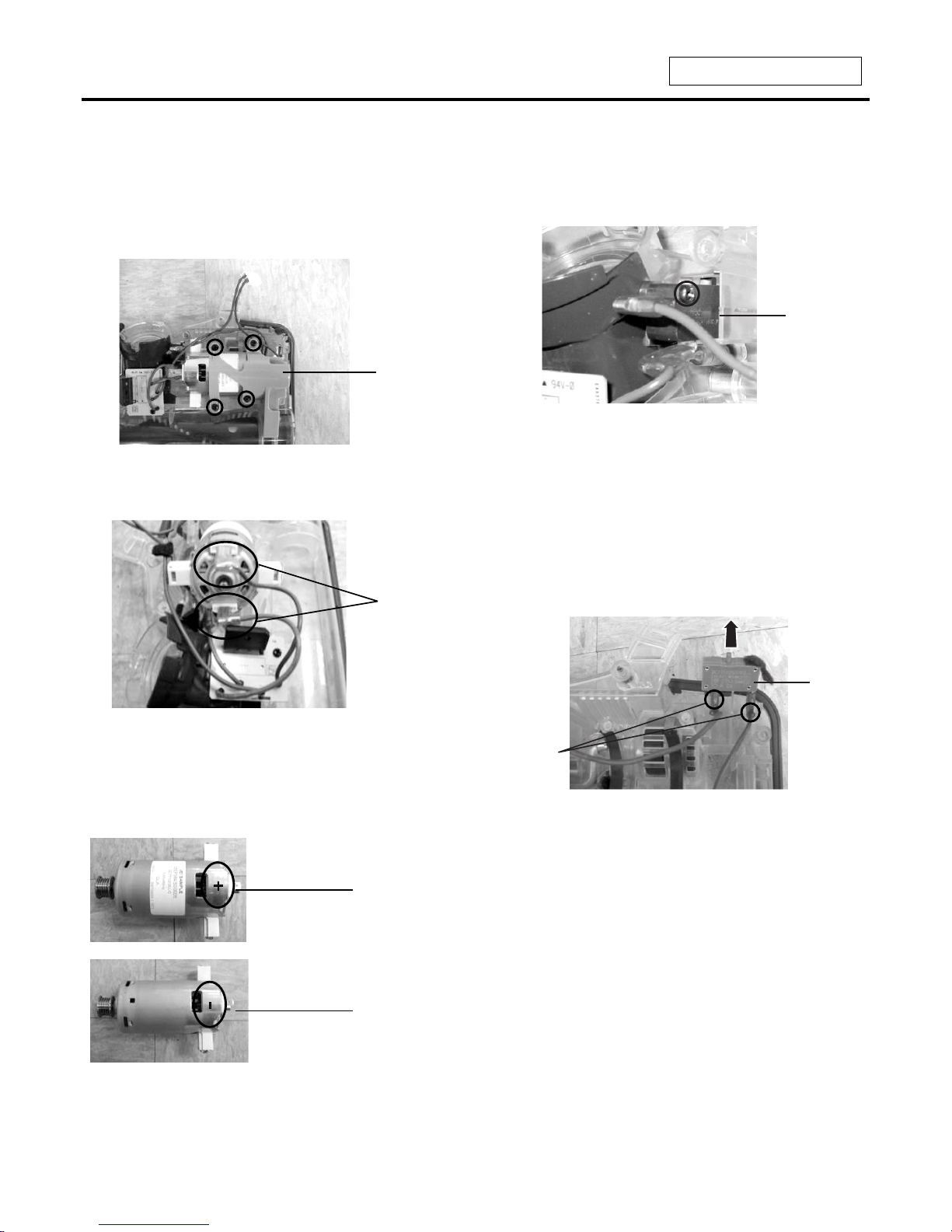
6. Agitator Motor replacement
1) Remove the agitator and belt as shown on
page 15.
2) Remove the 4 screws and pull out the Bracket.
3) Disconnect the 2 leads and remove the motor.
Note : This motor is marked ‘+’ on one side
and ‘ – ’ on the other side. Be sure to
connect properly. The wire color of ‘+’
is brown and ‘ - ’ is blue.
4) To reinstall the Agitator Motor reverse the
steps above.
7. Micro Switch replacement
1) Remove the 1 screw and disconnect the 2
leads and remove the Micro Switch.
2) To reinstall the Micro Switch reverse the
steps above.
8. Fuse Break replacement
1) Lift the Fuse Break to the direction shown
and disconnect the 2 leads and then remove
the Fuse Break.
2) To reinstall the Fuse Break reverse the
steps above.
4. DISASSEMBLY
Bracket
2 Ieads
Positive
Pole (+)
Negative
Pole (-)
Fuse
Break
2 leads
Micro
Switch
- 9 -
 Loading...