

Sears 583.756700,583.756730,583.756720 Owner's Manual
OWNER’S
MANUAL
MODEL
NUMBERS:
583.756700
583.756720
583.756730
SERIAL NO.
(owner - write in No.)
CA UTION:
Read Rules for
Safe Operation
40,000 60,000 and 115,000 Btu/Hr
Heater Sizes:
and Instructions
Carefully
Operation and Maintenance
Instructions with Parts List
SAVE THIS MANUAL FOR
FUTURE REFERENCE
®
ARL LOGO
Sold by Sears, Roebuck and Co., 3333 Beverly Road, Hoffman Estates, IL 60179
G 004
40,000, 60,000 and 115,000 Btu/Hr
PORTABLE FORCED AIR HEATERS
WARRANTY
For one year from the date of purchase,
Sears will repair any defect in material or
workmanship in this portable heater at no
charge.
If the portable heater is used for commercial
or rental purposes, this warranty applies for
only thirty days from the date of purchase.
Warranty service is available by simply
returning the heater to the nearest Sears
Service Center. This warranty gives you the
specific legal rights, and you may also have
other rights which vary from state to state.
Sold by Sears, Roebuck and Co., 3333
Beverly Road, Hoffman Estates, IL 60179
SAFETY
INFORMATION
WARNINGS
IMPORTANT: Read this Owner’s
Manual carefully and completely
before trying to assemble, operate, or service this heater. Improper use of this heater can
cause serious injury or death from
burns, fire, explosion, electrical
shock, and carbon monoxide
poisoning.
DANGER: Carbon monoxide
poisoning may lead to death!
Carbon Monoxide Poisoning: Early
signs of carbon monoxide poisoning resemble the flu, with headaches, dizziness,
and/or nausea. If you have these signs, the
heater may not be working properly. Get
fresh air at once! Have heater serviced.
Some people are more affected by carbon
monoxide than others. These include pregnant women, persons with heart or lung
disease or anemia, those under the influence
of alcohol, and those at high altitudes.
Make certain you read and understand all
Warnings. Keep this manual for reference.
It is your guide to safe and proper operation
of this heater.
• Use only kerosene or No. 1 fuel oil to
avoid risk of fire or explosion. Never use
gasoline, naphtha, paint thinners, alcohol, or other highly flammable fuels.
• Fueling
a)Personnel involved with fueling shall
be qualified and thoroughly familiar
with the manufacturer’s instructions
and applicable federal, state, and local regulations regarding the safe
fueling of heating units.
b)Only the type of fuel specified on the
heater’s data plate shall be used.
c) All flame, including the pilot light, if
any, shall be extinguished and the heater
allowed to cool, prior to fueling.
d)During fueling, all fuel lines and fuel-
line connections shall be inspected for
leaks. Any leaks shall be repaired prior
to returning the heater to service.
e)At no time shall more than one day’s
supply of heater fuel be stored inside
a building in the vicinity of the heater.
Bulk fuel storage shall be outside the
structure.
f) All fuel storage shall be located a
minimum of 25 feet from heaters,
torches, welding equipment, and
similar sources of ignition (exception: the fuel reservoir integral with
the heater unit).
g)Whenever possible, fuel storage shall
be confined to areas where floor penetrations do not permit fuel to drip
onto or be ignited by a fire at lower
elevation.
h)Fuel storage shall be in accordance
with the federal, state, or local authority having jurisdiction.
• Never use heater where gasoline, paint
thinner, or other highly flammable vapors are present.
• Follow all local ordinances and codes
when using heater.
• Heaters used in the vicinity of tarpaulins, canvas, or similar enclosure materials shall be located a safe distance
from such materials. The recommended
minimum safe distance is 10 feet. It is
further recommended that these enclosure materials be of a fire retardant nature. These enclosure materials shall be
securely fastened to prevent them from
igniting or from upsetting the heater
due to wind action.
• Use only in well-vented areas. Before
using heater, provide at least a threesquare-foot opening of fresh, outside
air for each 100,000 Btu/Hr of rating.
This heater produces carbon monoxide,
which is listed by the State of California as a reproductive toxin under Proposition 65.
• Use only in places free of flammable
vapors or high dust content.
• Use only the electrical voltage and frequency specified on model plate.
• Use only a three-prong, grounded extension cord.
• Minimum heater clearances from combustibles:
Outlet: 8 Ft. Sides: 4 Ft.
Top: 4 Ft. Rear: 4 Ft.
• Locate heater on a stable and level surface if heater is hot or running or a fire
may occur.
• When moving or storing heater, keep
heater in a level position or fuel spillage may occur.
• Keep children and animals away from
heater.
• Unplug heater when not in use.
• This heater is equipped with a thermostat. Heater may start anytime.
• Never use heater in living or sleeping
areas.
• Never block air inlet (rear) or air outlet
(front) of heater.
• Never move, handle, refuel, or service
a hot, operating, or plugged-in heater.
• Never attach duct work to front or rear
of heater.
2
104980
OWNER’S MANUAL
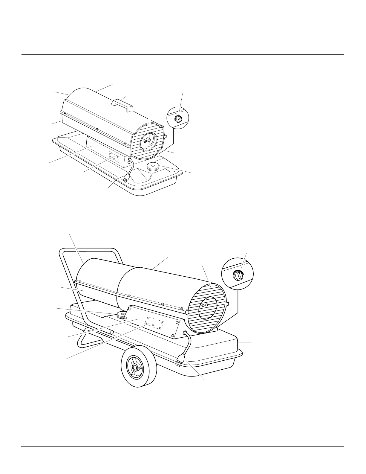
PRODUCT IDENTIFICATION
Upper Shell
Hot Air Outlet
Lower Shell
Fuel Tank
Side Cover
Ignition Control Assembly
(assembly on inside of side cover)
Power Cord
Figure 1 - 40,000 & 60,000 Btu/Hr Models
Hot Air
Outlet
Handle
Fan Guard
Thermostat Knob
Air Filter
End Cover
Fuel Cap
UNPACKING
1. Remove all packing items applied to
heater for shipment.
2. Remove all items from carton.
3. Check items for shipping damage. If
heater is damaged, promptly inform
dealer where you bought heater.
Lower Shell
Fuel Cap
Side Cover
Ignition Control
Assembly (assembly on
inside of side cover)
Figure 2 - 115,000 Btu/Hr Model
Thermostat Knob
Upper Shell
Fan Guard
Fuel Tank
Power Cord
104980
3
40,000, 60,000 and 115,000 Btu/Hr
PORTABLE FORCED AIR HEATERS
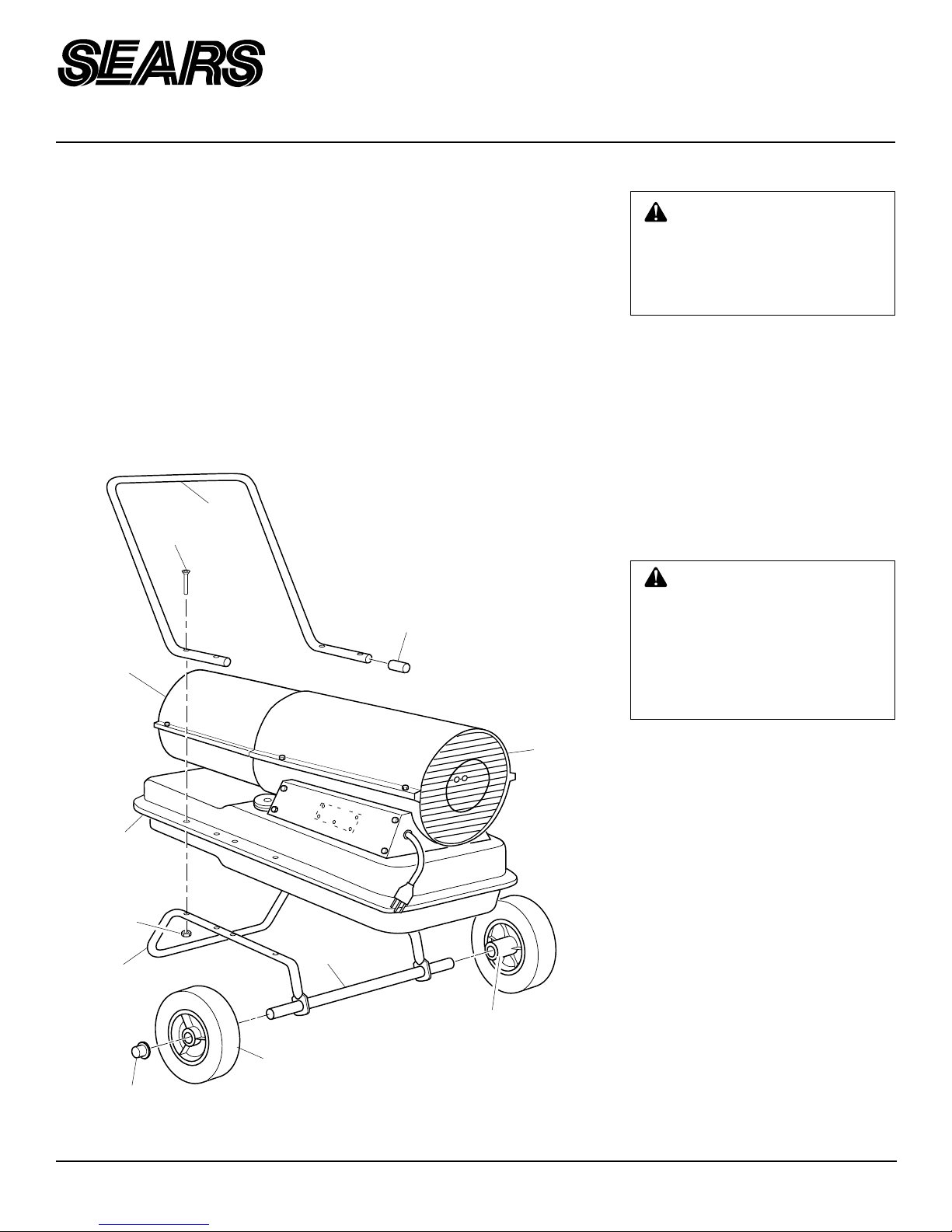
ASSEMBLY
Some models are furnished with wheels and
a handle. Wheels, handle, and the mounting
hardware are found in the shipping carton.
Tools Needed
• Medium Phillips Screwdriver
• 3/8" Open or Adjustable Wrench
• Hammer
1. Slide axle through wheel support
frame. Install wheels on axle.
IMPORTANT:
point extended hub of wheels toward
wheel support frame (see Figure 3).
Hot Air
Outlet
When installing wheels,
Handle
Screw
2. Place cap nuts on axle ends. Gently tap
with hammer to secure.
3. Place heater on wheel support frame.
Make sure air inlet end (rear) of heater
is over wheels. Line up holes on fuel
tank flange with holes on wheel support frame.
4. Place handle on top of fuel tank flange.
Insert screws through handle, fuel tank
flange, and wheel support frame. Attach nut finger tight after each screw is
inserted.
5. After all screws are inserted, tighten
nuts firmly.
Plastic
Tube Cap
FUELS
WARNING: Use only kerosene
or No. 1 fuel oil to avoid risk of fire
or explosion. Never use gasoline, naphtha, paint thinners, alcohol, or other highly flammable
fuels.
Do not use heavy fuels such as No. 2 fuel oil
or No. 2 Diesel. Using heavy fuels will
result in a clogged fuel filter and/or nozzle.
IMPORTANT:
storage container. Be sure storage container
is clean. Foreign matter such as rust, dirt, or
water will cause the ignition control assembly to shut down the heater. Foreign matter
may also require you to clean fuel system
often.
Use a KEROSENE ONLY
VENTILATION
Follow the minimum fresh,
outside air ventilation requirements. If proper fresh, outside air
ventilation is not provided, carbon monoxide poisoning can
occur. Provide proper fresh, outside air ventilation before running heater.
Fuel Tank
Flange
Nut
Wheel Support
Frame
Wheel
Cap Nut
Figure 3 - Wheel and Handle Assembly
Axle
Air Inlet
Extended Hub
4
Provide at least a three-square-foot opening
of fresh, outside air for each 100,000 Btu/Hr
rating. Provide extra fresh air if more heaters are being used.
Example:
quires one of the following:
• a two-car garage door (16 feet wide opening) raised three inches
• a single-car garage door (9 feet wide
opening) raised five inches
• two 30 inch wide windows raised eight
inches
A 115,000 Btu/Hr heater re-
104980
OWNER’S MANUAL
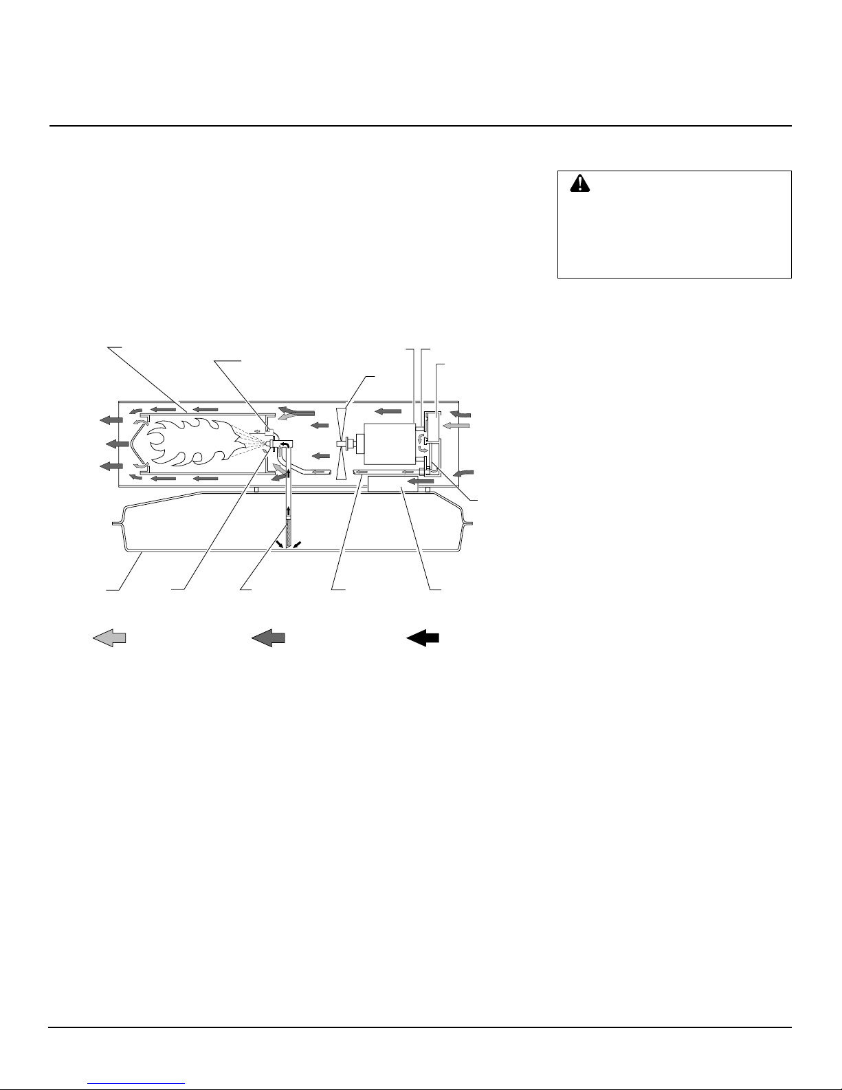
THEORY OF OPERATION OPERATION
The Fuel System: The air pump forces
air through the air line. The air is then
pushed through the nozzle. This air causes
fuel to lift from the tank. A fine mist of fuel
is sprayed into the combustion chamber.
The Air System: The motor turns the fan.
The fan pushes air into and around the
combustion chamber. This air is heated and
provides a stream of clean, hot air.
Combustion Chamber
Ignitor
Clean
Heated
Air Out
Fuel
Tank
Figure 4 - Cross Section Operational View
Nozzle
Air For Fuel System
Fuel
Filter
The Ignition System: The ignition con-
trol assembly provides power to the ignitor.
This ignites the fuel/air mixture in the combustion chamber.
The Flame-Out Control System: This
system causes the heater to shut down if the
flame goes out.
Motor
Fan
Air Pump
Air Intake
Filter
Cool
Air
In
Air
Output
Filter
Air Line
To Burner
Air For Combustion
And Heating
Ignition Control
Assembly
Fuel
WARNING: Review and un-
derstand the warnings in the
Safety Information
section, page
2. They are needed to safely operate this heater. Follow all local
codes when using this heater.
TO START HEATER
1. Follow all ventilation and safety infor-
mation.
2. Locate heater to provide maximum cir-
culation of the heated air. Follow all
location requirements noted in Safety
Information, page 2.
3. Fill fuel tank with kerosene or No. 1
fuel oil.
4. Attach fuel cap.
5. Turn thermostat knob clockwise to the
HIGH position.
6. Plug power cord of heater into three-
prong, grounded extension cord. Extension cord must be at least six feet long.
Extension Cord Wire Size Requirements
•
6 to 10 feet long, use 18 A WG rated cord
• 11 to 100 feet long, use 16 AWG
rated cord
• 101 to 200 feet long, use 14 AWG
rated cord
7. Plug extension cord into standard 120
volt/60 hertz, three-hole, grounded outlet.
Note:
Ignitor will preheat for five
seconds then heater will start.
8. Adjust thermostat knob to the desired
setting.
the thermostat setting. Further adjustments may be needed until the heater
cycles at the desired setting. This thermostat is a general-heating control. It
is not intended for precise temperature
control.
Note:
A cold heater may affect
104980
TO STOP HEATER
1. Unplug extension cord from outlet.
TO RESET HEATER
1. Unplug extension cord from outlet and
wait 10 seconds (two minutes if heater
has been running).
2. Repeat steps 5 through 8 of To Start
Heater.
5

40,000, 60,000 and 115,000 Btu/Hr
PORTABLE FORCED AIR HEATERS
STORING,
TRANSPORTING,
OR SHIPPING
Note:
If shipping, transport companies re-
quire fuel tanks to be empty.
1. Drain fuel tank. Drain fuel through fuel
cap opening. Be sure all fuel is removed.
2. If any debris is noted in old fuel, add 1
or 2 quarts of clean kerosene to tank,
stir, and drain again. This will prevent
excess debris from clogging filters during future use.
3. Replace fuel cap. Properly dispose of old
and dirty fuel. Check with local automotive service stations that recycle oil.
4. If storing, store heater in dry place.
Make sure storage place is free of dust
and corrosive fumes.
IMPORTANT:
summer months for use during next heating
season. Using old fuel could damage heater.
Do not store kerosene over
PREVENT A TIVE
MAINTENANCE
SCHEDULE
Item
Fuel tank
Air output and
lint filters
Air intake
filter
Fuel filter
Ignitor
Fan blades
Motor
How Often
Flush every 150-200 hours of operation or as needed
Replace every 500 hours of operation
or once a year
Wash and dry with soap an water every
500 hours of operation or replace as
needed
Clean twice a heating season or replace as needed
No maintenance required
Clean each season or as needed
Not required/permanently lubricated
WARNING: Never service heater
while it is plugged in, operating, or
hot. Severe burns and electrical
shock can occur.
How To
See Storing, Transporting, or
Shipping
See Air Output, Air Intake,
and Lint Filters, page 8
See Air Output, Air Intake,
and Lint Filters, page 8
See Fuel Filter, page 9
See Fan, page 8
6
104980
 Loading...