

Sears 565.60586000 User Manual
SEARS
DIVISION 20
SUPPLEMENTARY
BASIC FIELD MANUAL
FOR
MICROWAVE OVEN
MODEL 565.60586000
MARCH 2000
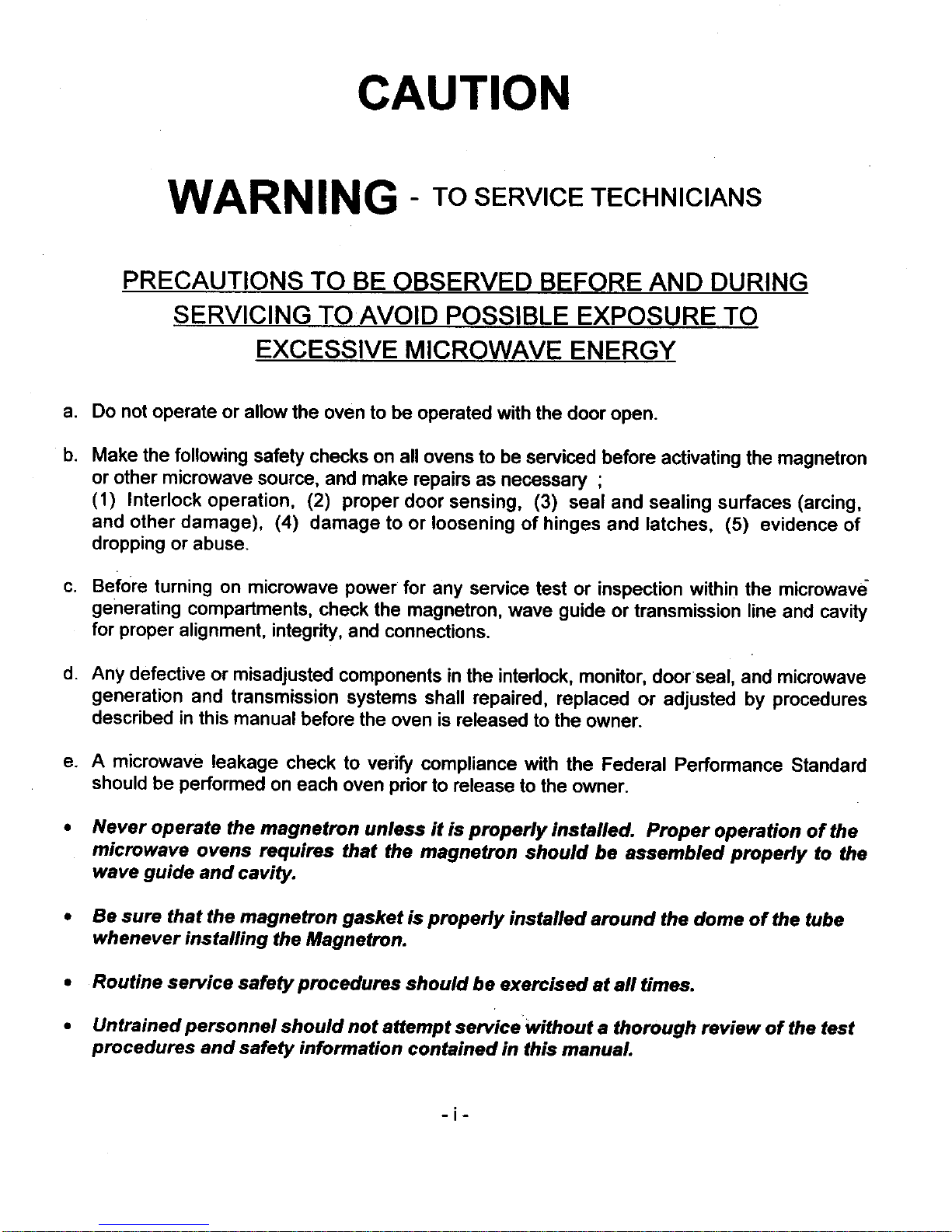
CAUTION
WARNING- TO SERVICE TECHNICIANS
PRECAUTIONS TO BE OBSERVED BEFORE AND DURING
SERVICING TO AVOID POSSIBLE EXPOSURE TO
EXCESSIVE MICROWAVE ENERGY
a. Do not operate or allow the oven to be operated with the door open.
b,
Make the followingsafety checks on all ovens to be serviced before activating the magnetron
or other microwave source, and make repairs as necessary ;
(1) Interlock operation, (2) proper door sensing, (3) seal and sealing surfaces (arcing,
and other damage), (4) damage to or loosening of hinges and latches, (5) evidence of
dropping or abuse.
c. Before turning on microwave power for any service test or inspection within the microwave
generating compartments, check the magnetron, wave guide or transmission line and cavity
for proper alignment, integrity, and connections.
d. Any defective or misadjusted components in the interlock, monitor, door seal, and microwave
generation and transmission systems shall repaired, replaced or adjusted by procedures
described in this manual before the oven is released to the owner.
e. A microwave leakage check to vedfy compliance with the Federal Performance Standard
should be performed on each oven prior to release to the owner.
, Never operate the magnetron unless it is properly installed. Proper operation of the
microwave ovens requires that the magnetron should be assembled properly to the
wave guide and cavity.
• Be sure that the magnetron gasket is properly installed around the dome of the tube
whenever installing the Magnetron.
• Routine service safety procedures should be exercised at aft times.
• Untrained personnel should not attempt servicewithout a thorough review of the test
procedures and safety information contained in this manual.
-i-
CAUTION For microwave
energy emission
On every service call, checks for microwave
energy emission must be made according to the
following manner.
Measurement of energy emission
Measurement must be made with the microwave
oven operating at its maximum output and
containing a load of 275:1:15 milliliters of tap water
initially at 20°C + 5°C celsius (68°F :1: 9oF)
placed within the cavity at the center.
NOTE :
The water container must be a 600 milliliter
beaker and made of an electrically
nonconductive material such as glass
or plastic.
The cook tray mus._tbe in place when
measuring em=sslon.
A properly operating door and seal assembly will
normally resister small emissions but they must be no
greater than 4mwlcm 2 to allow for measurement
uncertainty.
All repairs must be performed in such a manner
that mfcrowave energy emission is minimal.
Follow the instructions supplied with the survey
meter being used and perform an R.F. emission
test around the door front and edges and all
edges and vents of the outer case. The cabinet
(wrapper) must be in place and the oven fully
assembled.
When performing an emission survey, the meter
should be set on FAST RESPONSE and the movement
of the Survey Meter probe shall not exceed one (1) inch
per second.
In the area emitting the highest reading, switch the
meter to SLOW RESPONSE and take a reading for
minimumof three (3) seconds.
We recommend the pattern outline shown in below
when the doorsurface is surveyed.
NOTE:
Periodically check to be sure that the probe
tip is notworn or dirty.
I MODEL
565.60586000 I
The followin,q U.S. standard
aUDlies to microwave ovens : 21
CFR 1030. 10, Performance
Standard for Microwave Ovens.
It requires that the power density of the
microwave radiation emitted by a microwave
ovens shall not exceed five (5) milliwatts per
square centimeter at any point 5 centimeter
(about 2 inches) or more from the external
surface of the oven.
All microwave ovens exceed n,q the emission level of
4mw/cm z must be reported to Dept. of Service for
microwave ovens andthe manufacture immediately
and the owner should be told not to use the microwave
oven untillit has been repaired completely.
If a microwave oven is found to operate with the
d.Qg.LqJ_=a3,_reportto Dept. of Service, the manufacture
and CDRH* immediately. Also tell the owner notto use
the oven.
* CDRH : Center for Device and Radiological
Health.
The interlock monitor switch acts as the finat safety
switch protecting the customer from microwave
radiation. If the interlock monitor switch (_oerates
to blow the fuse with intedocks failed, you must replace
all interlock switches - primary and secondary
interlock switches and the monitor switch with new
ones because the contacts of those interlock switches
may be melted and welded together.
-ii-
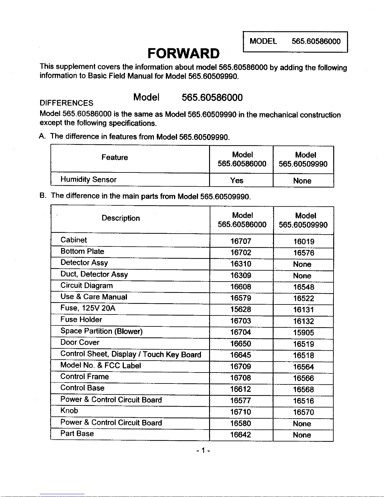
FORWARD I MODEL565.60586000I
This supplement covers the information about model 565.60586000 by adding the following
information to Basic Field Manual for Model 565.60509990.
DIFFERENCES
Model 565.60586000
Model 565.60586000 is the same as Model 565.60509990 in the mechanical construction
except the following specifications.
A. The difference in features from Model 565.60509990.
Feature Model
565.60586000
Humidity Sensor Yes
B. The difference in the main parts from Model 565.60509990.
Model
565.60509990
None
Description
Cabinet
Bottom Plate
Detector Assy
Duct, Detector Assy
Circuit Diagram
Use & Care Manual
Fuse, 125V 20A
Fuse Holder
Space Partition (Blower)
Door Cover
Control Sheet, Display I Touch Key Board
Model No. & FCC Label
Control Frame
Control Base
Power & Control Circuit Board
Knob
Power & Control Circuit Board
Part Base
Model
565.60586000
16707
16702
16310
16309
16608
16579
15628
16703
16704
16650
16645
16709
16708
16612
16577
16710
16580
16642
Model
565.60509990
16019
16576
None
None
16648
16522
16131
16132
15905
16519
16518
16564
16566
16568
16516
16570
None
None
-1-
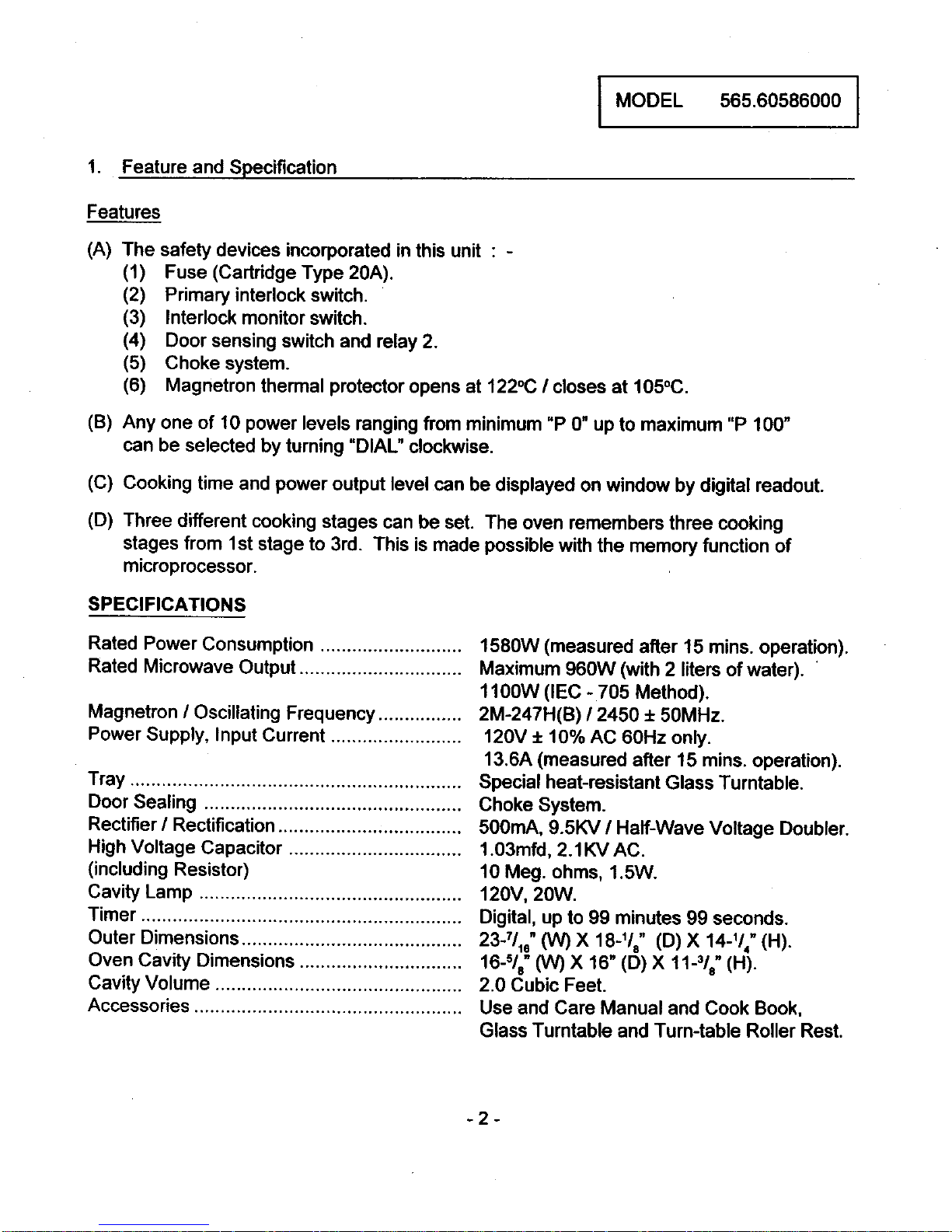
I MODEL 565.60586000 I
1. Feature and Specification
Features
(A) The safety devices incorporated in this unit : -
(1) Fuse (Cartridge Type 20A).
(2) Primary interlock switch.
(3) Interlock monitor switch.
(4) Door sensing switch and relay 2.
(5) Choke system.
(6) Magnetron thermal protector opens at 122°(3 / closes at 105°C.
(B) Any one of 10 power levels ranging from minimum "P 0" up to maximum "P 100"
can be selected by turning "DIAL" clockwise.
(C) Cooking time and power output level can be displayed on window by digital readout.
(D) Three different cooking stages can be set. The oven remembers three cooking
stages from 1st stage to 3rd. This is made possible with the memory function of
microprocessor.
SPECIFICATIONS
Rated Power Consumption ........................... 1580W (measured after 15 mins. operation).
Rated Microwave Output ............................... Maximum 960W (with 2 liters of water). '
1100W (IEC - 705 Method).
Magnetron / Oscillating Frequency ................ 2M-247H(B) / 2450 + 50MHz.
Power Supply, Input Currant ......................... 120V + 10% AC 60Hz only.
13.6A (measured after 15 mins. operation).
Tray ............................................................... Special heat-resistant Glass Turntable.
Door Sealing ................................................. Choke System.
Rectifier / Rectification ................................... 500mA, 9.5KV / Half-Wave Voltage Doubler.
High Voltage Capacitor ................................. 1.03mfd, 2.1KV AC.
(including Resistor) 10 Meg. ohms, 1.5W.
Cavity Lamp .................................................. 120V, 20W.
Timer ............................................................. Digital, up to 99 minutes 99 seconds.
Outer Dimensions .......................................... 233/10" (W) X 18-118" (D) X 14-1/4" (H).
Oven Cavity Dimensions ............................... 16-5/s" (W) X 16" (D) X 11-31a"(H).
Cavity Volume ............................................... 2.0 Cubic Feet.
Accessories ................................................... Use and Care Manual and Cook Book,
Glass Turntable and Turn-table Roller Rest.
-2-
 Loading...