Page 1
OWNER'S
MAHUAL
MODEL NO.
536.884821
Caution:
Read and Follow
All Safety Rules
and Instructions
Before Operating
This Equipment
CRRFr$IRN
5 HORSEPOWER
24" DUAL STAGE
FREE=WHEELIHG TRACK
SNOW THROWER
Optional Electric Start
• Assembly
=" Operation
Maintenance
• Service and Adjustments
= Repair Parts
-- [ ................................................. .._.... _ _ _ _ ql U q IIII1' ill
SEARS, ROEBUCK AND CO., Chicago, IL 60684 U.S.A.
..... , ................ i nl ii ii '11 IIII I _ ...... Z .......
Page 2
SAFETY RULES
CAUTION: ALWAYS DISCONNECT SPARK PLUG WIRE AND PLACE A
WIRE WHERE IT CANNOT CONTACT SPARK PLUG TO PREVENT
ACCIDENTAL STARTING WHEN SETTING-UP, TRANSPORTING, AD-
JUSTING OR MAKING REPAIRS.
IMPORTANT
SAFETY STANDARDS REQUIRE OPERATOR PRESENCE CONTROLS TO MINIMIZE THE
RISK OF INJURY. YOUR SNOW THROWER IS EQUIPPED WITH SUCH CONTROLS. DO NOT
ATTEMPT TO DEFEAT THE FUNCTION OF THE OPERATOR PRESENCE CONTROL UNDER
ANY CIRCUMSTANCES°
BEFORE USE
• Read the Owner's Manual carefully. Be thor-
oughly fan]iliar with the controls and the proper
use of the snow thrower. Know how to stop the
snow thrower and disengage the controls
quickly.
• Do not operate the snow thrower without wear-
ing adequate winter outer garments. Wear
footwear that will improve footing on slippery
surfaces. •
• Keep the area of operation clear of all persons,
particularly small chirdren, and pets.
• Thoroughly inspect the area where the snow
thrower is to be used and remove alldoormats,
sleds, boards, wires, and other foreign objects..
• Use extension cords and receptacles as
specified by the manufacturer for all snow
throwers with electric drive motors or with
factory-installed or optional starting motors
• Use only attachments and accessories ap-
provedby the manufacturer of the snow thrower
(such as eiectric starter kits, etc.)
o Never operate the snow lhrower without good
visibility or light. Always be sure of your foot}ng,
and keep a firm hold on the handles° Walk:
never run.
• This snow thrower is for use on sidewalks,
driveways, and other ground level surfaces.
CAUTION should be exercised whi(e using on
steep sloping surfaces. DO NOT USE SNOW
THROWER ON SURFACES ABOVE
GROUND LEVEL such as roofs of residences,
garages, porches or other such structures or
buildings,,
• Check shear bolts and other bolts at frequent
intervals for proper tightness to be sure the
snow thrower is in safe working condition.
• Disengage all clutches and shift into neutral
before starting the engine_
• ,Adjust the snow thrower height to clear gravel •
or crushed rock surface.
• Let engine and snow thrower adjust to outdoor
temperatures before starting to clear snow,
FUEL SAFETY
• Handle fuel with care; it is highly flammable.
• Use an approved fuel container,
• Check fuel supply before each use, aflowing
space for expansion as the heat of the engine
and/or sun can cause fuel to expand.
• Fill fuel tank outdoors with extreme care, Never
fill fuel tank indoors.
Replace fuel tank cap securely and wipe up
spilled fuel.
• Never remove fuel tank cap or add fuel to a
running engine or hot engine.
• Never store fuel or snow th rower wilh fuel in the
tank inside a building where fumes may reach
an open flame or spark.
OPERATING SAFETY
• Never atlow children or young teenagers to
operate the snow thrower and keep them away
while it is operating_ Never allow adults to
operate the snow thrower without proper in-
struction _ Do not carry passengers.
• Always wear safety glasses or eye shields
during operation or while performing .'n adjust-
ment or repair to protect eyes from foreign
objects that may be thrown from the snow
thrower.
• Exercise extreme caution when operating on or
crossing gravel drives, walks, or roads. Stay
alert for hidden hazards or traffic.
• Do not put hands or feet near or under rotating
parts. Keep clear of the discharge opening at
all times,,
• Exercise caution to avoid slipping or falling,
especially when operating in reverse or back-
ing up.
• Do not clear snow across the face of slopes.
Exercise caution when changing direction on
slopes_ Do not attempt to clear' steep slopes.
Neveroperate the snowthrowerwithoutproper
guards, plates or other safety protective de-
vices in place.
Page 3
SAFETY RULES
Never operate the snow thrower near glass
enclosures, automobiles, window wells, drop-
offs, and the like without proper adjustment of
the snow discharge angre. Keep children and
pets away_.
® Never operate the snow thrower at high trans-
port speeds on slippery surfaces_ Look behind
and use care when backing..
e Never direct discharge at bystanders or allow
anyone in front of the snow thrower.
® Do not run the engine indoors, except when
sta_ng the engine and for transporting the
snow thrower in or out of the building_ Open the
outside doors; exhaust fumes are dangerous
(containing CARBON MONOXIDE, an ODOR-
LESS and DEADLY GAS).
e Take all possible precautions when leaving the
snow thrower unattended_. Disengage the au-
gedimpeller, shift to neutral, stop engine, and
remove key,
e Do not overload the machine capacity by at-
tempting to clear snow at too fast a rate.
SAFE STORAGE
e Always refer to Owner's Manual instructions for
important details if the snow thrower is to be
stored for an extended period.
o Disengage power to the auger/impeller when
snow thrower is transported or not in use.
o Never store the snow thrower with fuel in the
fuel tank inside a building where ignition sources
are present such as hot water and space
heaters, clothes dryers, and the liken Allow the
engine to cool before storing in any enclosure_
REPAIR/ADJUSTMENTS SAFETY
o After striking a foreign object, stop the engine
remove the wire from the spark plug or dis-
connect the cord from the electric motor°
Thoroughly inspect the snow thrower for any
damage and repair the damage before restart-
ing and operating the snow thrower°
® If the snow thrower should start to vibrate
abnormally, stop the engine or electric motor
and check immediately for the cause. Vibration
is generally a warning of trouble.,
® Stop the engine or electric motor whenever
you leave the operating position before un-
clogging the auger/impeller housing or dis-
charge guide, and when making any repairs,
adjustments, or inspections. Removewire form
spark plug or disconnect cord from electric
motor.
• When cleaning, repairing, or inspecting, make
certain the auger/impeller and all moving parts
have stopped. Disconnect the spark plug wire
and keep the wire away from the plug to pre-
vent accidental staRting.
o Never attempt to make any adjustments while
the engine is running (exceptwhen specifically
recommended in this manual).
e Maintain or replace safety and instruction la-
bels, as necessary.
o Run the snow thrower a few minutes after
throwing snow to prevent freeze-up of the
auger/impeller.
LOOK FOR THIS SYMBOL TO POINT OUT
_ IMPOR'[ANT SAFETY PRECAUTIONS. IT
MEANS-ATTENTION!!! BECOME ALERT!I!
YOUR SAFETY IS INVOLVED.
3
Page 4
CONGRATULATIONS on your purchase of a Sears
Craftsman Snow _rower_ It has been designed, engi-
neered and manufactured to give you the best possible
dependability and performance.
Should you experience any problem you cannot easily
remedy, please contact your nearest Sears Service
Center/Department. We have competent, welt4rained
technicians and the proper tools to se_ce or repair this
uniL
Please read and retain this manual. 'The instructions will
enable you to assemble and maintain your snow thrower
_mpedy. Always observe the =SAFETY RULES."
MODEL
NUMBER 536_884821
SERIAL
NUMBER
DATE OF
PURCHASE
THE MODEL AND SERIAL NUMBERS WiLL BE
FOUND ON A DECAL ATTACHED TO THE REAR
OF THE SNOW THROWER HOUSING_
YOU SHOULD RECORD BOTH SERIALNUMBER
AND DATE OF PURCHASE AND KEEP IN A SAFE
PLACE FOR FUTURE REFERENCE°
MAINTENANCE AGREEMENT
A Sears Maintenance Agreement is available on this
product, Contact your nearest Sears Store for details_
PRODUCT SPECIFICATIONS
_SE POWER: 5 hp
: : :- ,,,,,,,,,,,,,,
DISPLACEMENT: 10.49
cu. In.
GASOLINE CAPACITY: 2 quart
........... m ,,,,,,,,, ..... - ......... Hi
OIL (20 oz., Capacity): SAE 10W-30 or
SPARK PLUG :
(GAP .030 In.)
VALVE CLEARANCE:
"S.AIF... 5W-30 motor O" maybe used to make
starting easier In areas where the temperature Is
20 ° F or lower.
OPTIONAL ACCESSORY
An electric starter kit (Stock No., 71-8894) is available for
this snow thrower and may be ordered through Sears
Retail or Catolog Stores Installation instructions for the
electric starter are included in this kit.
Unleaded
5W-30"
Champion
RJ19LM
Intake: .010 In.
Exhaust: .010 in.
CUSTOMER RESPONSIBILITIES
• Read and observe the safety rules°
• Follow a regular schedule in maintaining, caring tot and using your snow thrower.,
• FolJow the instructions under "Maintenance" and =Storage" sections of this owner's manual
TWO YEAR LIMITED WARRANTY ON CRAFTSMAN
SNOW THROWER
For two years from the date of purchase, when this Craftsman Snow Thrower is maintained, lubricated
and tuned-up according to the instructions in the owner's manual, Sears witl repair, free of charge, any
detect in material and workmanship.
It this Craftsman Snow Thrower is used for commercial or rental purposes, this warranty applies for only
90 days from the date of purchase.
This warranty does not cover the following:
• Expendable items which become worn dudng normal use, such as spark plugs, ddve belts and shear
p_so
Repairs necessary because of operator abuse or negligence, including bent crankshafts and the failure
to maintain the equipment according to the instructions contained in the owner's manual.
WARRANTY' SERVICE IS AVAILABLE BY RETURNING THE CRAFTSMAN SNOW THROWER TO THE
NEAREST SEARS SERVICE CENTER/DEPARTMENT IN THE UNITED STATES. THIS WARRANTY
APPLIES ONLY WHILE THIS PRODUCT IS IN USE iN THE UNITED STATES,
This wan_anty gives you specitic legal rights, and you may also have other dghts which may vary from
state to state.
SEARS, ROEBUCK AND CO. Department 731CR_W, Sears Tower, Chicago, tL 60684 ...................
.......... : :: ............ ,,,J=, i ..... ,,, ,,,,,, i uH= ........
4
Page 5
TABLE OF
SAFETY RULES .................................................... 2,3
PRODUCT SPECIFICATIONS ........................... 4
CUSTOMER RESPONSIBILITIES ................. 4
WARRANTY ...................................................... 4
TABLE OF CONTENTS .................................. 5
INDEX ............................................................. 5
ASSEMBLY ........................................................ 6-9
OPERATION ............................................. 10-14
CONTENTS
MAINTENANCE .............................................. 15-! 6
SERVICE AND ADJUSTMENTS ........... 17-24
STORAGE ..................................................... 25
SERVICE RECOMMENDATIONS ................. 26
TROUBLE SHOOTING ................................. 27
REPAIR PARTS (SNOW THROWER),.. 2B-40
REPAIR PARTS (ENGINE) ...................... 41-44
PARTS ORDERING/SERVICE ........ Back Cover
iNDEX
A
Adjustmen!:
Auger .............................................................. 1B
Bm! .................................................................. 18
Bett Gui_e ............................................... 20
Cabie ............................................................ t 8
Carburelor ............................................. 24
Frick;on Wheei ........................................ 21
Span P!ug ............................................... 24
Track .................................................... 23
Traction and Auger ................................. 18
Assemoly
Cran_ Assembly ........................... 8
ShiI!er Lever ......................................... 9
Skio Hergnt Adjustment ............. 7, 17
Unpac_iog ........................................... 7
Belts:
Ad)ust Belts ........................................... 18
Belt Gu_oe Adjustment ........................ 20
Bett Maintenance ................................. 15
Replace Belts .................................. 19, 20
Cables..C:_ch ..................................... 7, 9_ t 8
Ca_ure_.or: ........................................... 24, 25
Chain ............................................................ 15
Choke ............................................. ;O. 11, i3
Clutch Levers ............................. 10, 11
Conlro_s:
Engine .................................... 10, 11, t3, 14
SnowThrower ....................................... t0
Crank:
Adjusting Rod ............................................ 8, 17
Assemoly ........................................................... 8
Operaticn ...................................................... 11
Customer Responsibilities ............................ 4
Drive, Auger .................................................. 1 t
Ddveo Traction ......................................... 11
De|lectoro Snow Chute ............................... 11
B
C
D
E
Engine:
Control ............................... 10, 11, 13, 14
Oil Cap ................................................. 12, 16
Oil Change .................................................. t6
Oil Level ..................................................... 12, 16
Oil Type .................................. 4. 12, 16
Speed Governor ................................................. 24
Starting ...................................................... t 3
Storage ............................................................. 25
F
Free-Wheel. Track ...................................... 12
Fuel. Type ............................................. 4. I3
Fuel, Storage .................................... 13, 25
Friction Wheel:
Adjustment ........................................... 21
Replacement ................................... 22
Gears:
Auger Gear Box ................................. 15
Hex Shaft ............................................ 15
Hanoi{e, Upper ano Lower ...................... B
Height Adjust Skids ......................... 7, 17
Hex Shaft ................................... 15.22
[gnilion. Key ............................ ";0.1 I, 13, 14
!ndex ................................................................ 5
Levers
AugerDrive Clutch .. 7.9, 10, 1 Io 18
Choke ......................................... I0, 1 I. 13, I4
Shffler ....................................................... 9, 10
Throttle Controt .......... I0, 11,13, 14
Traction Dr_e Clulcn ..7.. 9, 10, 11, 18
Lubrication:
Auger Gear Box .................................. 15
Auger Shatt .................................. 15, 26
Chart .................................................... 26
Engine ........................................................ 14, 16
Hex Shaft and Gears ........................... 15
Weight Trans|er System ............... 12, 15
Maintenance:
Agreement ............................................................ 4
Auger Gear Box ..................................... 15
Auger Shaft ................................................. 15
Engine ................................................................ 16
GeneraIRecommenoations ............. 15
Hex Shaft and Gears ......................... 15
Weight Transfer System ...................... 15
Oil:
Engine .......................................... 4, 12, 16
Extreme Cold Weather .................... 13,16
Storage .............................................................. 25
Type ...................................................... 4, 12, 16
Operation:
Engine Controls ............... 10,11, 13,14
Free-Whee!, Track ..................................... 12
Operating Snow Thrower.... 11, 12, t 4
G
H
l
L
M
O
Operating Tips .................................................. t4
Starting the Engine ...................................... I3
Snow Thrower Controls ................... 10-12
Weight Transfer System .......................... 12
P
Parts ................................................................. 28-39
PrimerButton ..................... ;0, _ !. _3. ;4
RepatrlReplacement Parts ............ 28-39
Replacemenls:
Auger Shear Bolt .......................................... 23
Belts .................................................... 19.20
Friction Wheel ................................. 22
Satety Rules ................................................. 2.3
Service and Adjustments:
Auger Housing Height ....................... 7.17
Auger Shear Bolt ........................................... 23
Betts ....................................................... 18-20
Belt Guide ............................................................ 20
Belt Replacements .............................. 19, 20
Cable ........................................................ 7, 9, 1
Carburetor .................................................... 24, 25
Friction Wheel .......................................... 22
Spark Rug .......................................................... 24
Track ....................................................................... 23,
Se rv k?.e Recommendations .................... 26
Spark Plug ............................................ 18, 24
Specifications .................................................. 4
Speed Governor ................................................. 24
Starting the Engine ......................................... t 3
Stopping the Engine ....................... 11, 13.14
Stopping the Snow Thrower .................... 11
Shipping Oarton ..................................... 6, 7
Skid Height ...................................................... 7, 17
ShitTer Lever ................................................. 9-I0
Shear Bofts ....................................................... 23
Storage ............................................................ 25
Table ol Contents .................................... 5
Trouble Shooting Chart .................... 26
Tools for Assembly ..................................... 6
Traction Drive Bert ................................... 18, 20
Track Adjustmanl .......................................... 23
Warranty ....................................................... 4
Weight Transter System ...................... 12, t5
R
S
T
W
5
Page 6
lllll ,,,, ................
ASSEMBLY
............................................. ii i!111 .................
THIS SNOW TI-IROWER HAS A TRACK DRIVE SYSTEM EQUIPPED TO GIVE
YOU FREE-WHEELING CAPABILITY
If your snow thrower must be moved without the aid of the engine, it will be easier to pull the snow thrower
backward by the handles, rather than pushing. For details on how to use the free-wheeling capability, see the
Track Drive/Free-Wheel Feature paragraph in the Operation section of this manual
On start up, the track drive system may be tight but will loosen up as the snow thrower is used After first use, check
the track for tension and adjust if necessary., See the "track Adjustment paragraph in the Service and
Adjustments section of this manual. Check track adjustment and fasteners reguladyo
CONTENTS OF SHIPPING CARTON
1 - Snow thrower completely assembled except for
the crank assembly, and the upper handle, which
is in the folded down position.
1 - Parts bag containing:
1 - Owner's manual (not shown) and
Pans shown below:
CONTENTS OF PARTS BAG
............... i I IIIII I II I I IIIIIIII II1'11111[11 I i, iiiiiiiiiiiiii ii i III
TOOLS REQUIRED FOR ASSEMBLY
1 - Knife (to cut carton and plastic ties)
2 - 1/2 inch wrenches (or a_ustabre wrenches)
2 - 9f16 inch wrenches (or adjustable wrenches)
2 - 3/4 inch wrenches (or adjustable wrenches)
1 - Pliers (Io spread cotter pin)
1- Screwdriver
°2 - Spa_e 114-20 x 1-3/4
In. Hox Head Screws
"Non-Assembled Parts
ill IH,IL IJ ,,,I[HIIII _',11' III ............ , ,
1 - Knob with Threads
"2 - Spare Spacers
"2 - Spare 1/4-20 Hex nuts
2 _ iginition Keys
6
Page 7
...................... ASSE .......... L¥ .............. ' .............
Hi, _lll, lllll, .......... -.. ........................ ii ll.i ill _,_
Figure 1 showsthe snowthmwer in the shipping position.
Figure 2 shows the snowthrowercomptetety assembled,
Reference to the righl and left hand side of the snow
thrower is from the operator's position at the handle,,
TO REMOVE SNOW THROWER
FROM CARTON (See Fig. 1)
e Remove the staples from top of carton.
o Locate the crank assembly and place the assembly
aside,
e Remove and discard the packing material from
around the snow thrower,.
® Cut all four comers of the carton from top to bottom
and lay lay the panels flat,.
e Remove the packing material from the shifter plate
and upper handle assembly.
e Rollthe snow lhmweroff the carton by pulling on the
lower handle,,
NOTE: The drive system may be tight when you first use
your snow thrower. It loosens up as you use ito
e To complete upper handle installation and install
chute crank assembly, see To Install The Upper Handle
and Crank Assembly paragraph on page 8.
NOTE: If the cables have become disconnected from the
clutch levers, reinstall the cables as shown in Fig. 3,
,,, .__..:. ...................... .......................................... .,_:..
LOWER HANDLE CONTROL PANEL
CLUTCH
CABLE
UPPER
HANDLE
ASSEMBLY
CRANK ASSEMBLY
CHUTE
CLUTCH
CABLES
SHIFTER
DEFLECTOR
HOW TO SET UP YOUR SNOW
THROWER
o
Your snow thrower is equipped with height adjust
skids (See Fig. 2) on the outside of the auger
housing,, To adjust the skid height for different
conditions, see To Adjust Skid Height paragraph on
page 17._
CAUTION: IF YOU ARE REMOVING
,_ SNOW FROM ANY ROCKY OR UNEVEN
SKIDS DOWN. THIS WILL HEt.P TO PREVENT
ROCKS AND OTHER DEBRIS FROM BEING
PICKED UP AND THROWN BY THE AUGER,
.............. _ ;; _ .......... ....... ±
SURFACE, RAISE THE FRONT OF THE
SNOW THROWER BY MOVING THE
7
"Z" FITTING
FIG. 2
TRACTION
DRt!/E
LEVER
FIG. 3
Page 8
i i illll, ii,i ii ,ll .... , ....................................
MBLY
TO INSTALL THE UPPER HANDLE AND
CRANK ASSEMBLY
• Remove the screws, flatwashers, to.washers and
hex nuts secudng the shifter plate in the lower holes
of the lower handle..
• Loosen, t_Jt do not remove, the screws, flatwashers,
lockwashers, and hex nuts in the upper holes of the
lower handle_
• Raise upper handle into operating position., Upper
handle should be to the outside of the lower handle
and shifter plate to the inside.
• Replace the screws0 flatwashers, lockwashers, and
hex nutsthroughthe handles and shifter plate. Do not
lighten until all bolts are in ptace_ T'_jhten left hand
side first.
NOTE: Unless you have the assistance of another per-
son, it may be easier to install one side of the handle at the
time.
• Tighten the screw, flat'washer, Iockwasher and hex
nut at the upper dght hand hole only (See Fig, 4A),
• Remove the screw, flatwasher, Iockwasher and hex
nut from the upper left hand hole of the lower handle
and discard,
• Remove the 3/8" nylon iocknut and flatwasher from
the eye bolt assembly (on lhe chute crank assembly
eadier)_ Check to make sure the two 3/8" jam nuts are
tight. The jam nuts should be 3.75 inches from the
endof the eye bolt (Fig. 4B).
• Install eye bolt through lower hole on the left hand
side of the handle (See Fig., 4B)_
• Install the 3/8" ftatwasher and the 3/8" nylon locknut
loosely on the eye bolt as shown in Fig_ 4Bo
• Remove theptastic cap, the cotter pin andthewasher
from the wormed end of the crank assembly and set
aside (See Fig° 5)_
• Rotate the notched section of the discharge chute
toward the crank*adjusting rod..
• Install the wormed end of the crank through the hole
in the adjusting rod and secure the end with the flat
washer and cotter pin, as shown in Fig. 5
• Bend the ends of the cotter pin around the rod and
reinstall the plastic cap.
• Tighten the eye bolt installed earlier, keeping eye in
line with the rod while tightening the inside securely
• Make sure the outside 3/8" jam nut is up against the
other 3/8" jam nut and slide the boot over the adapter
(See F_,. 4B).
• Rotate the chute crank fully clockwise and fully
counter-clockwise, The discharge chute should
rotate fully with approximately 1/8 inch clearance
between the worm and the bottom of the notch (See
Fig. 5).
................................................. engine or the cover will be scratched,: ......................................................................
= _
• If the chute crank needs to be adjusted, go to the
NOTE: Be sure the crank does not touch the side of the
8
_'tB"
FIG. 4A
FIG. 5
Service and Adjustments section on page 17_
Screws securing chute clips at the base of the chute
should be slightly loose for easy rotation.
i/ J iui
Page 9
ASS LY
,llll
TO iNSTALL SHIFTER LEVER KNOB
0 Thread the shifter lever knob onto the threaded end
of the shifter lever until it is snug against the hex rut
and the lip is pointed toward the engine. T_jhten the
hex nut against the bottom of the shift leverknob_ (See
Fig, 6,)
..................... i ,,I,L
SNIFTER KNOB
NUT
LEVER
FIG. 6
TO CHECKJADJUST CLUTCH
CONTROL CABLES
The control cables, Fig. 7, attached to the auger clutch
lever and traction clutch lever may need to be adjusted
before you use your snow thrower,,
For instructions on checking or adjusting the control
cables, see To Adjust Clutch Control Cables paragraph on
page 18,
i I I i,,11 iiiiiiiiiiii _T : :
AUGER CLUTCH TRACTION CLUTCH
LEVER LEVER
OFF OFF
ON ON
CONTROL CABLES
................ F,G. 7
Page 10
.......... IJWIILI IlU III IIII , , iiiiii IIIIIIIII I I II I IIIIII _ II I II i ..... III1'1111 i ii
OPERA: ION
KNOwYOUR SNow THROWER .............................................................................
READ THIS OWNER'S MANUAL AND SAFETY RULES BEFORE OPERATING YOUR SNOW
THROWER. Compare the illustrations with your snow thrower to famgiarize yourseff with the location of vadous
commls and adjustments. Save this manual for future reference,
AUGER DRIVE
LEVER
SPEED
LEVER
WEmHr
PEDAL CHUTE
'TRACTION DRNE
CRANK
ASSEMBLY
CHUTE
DEFLECTOR
PRIMER B bq'TON
STARTER
CHOKE CONTROL HANDLE
THROTTLE CONTROL
HEIGHT ADJUST
FIG. 8
SEARS FREE-WHEELING SNOW THROWERS conform to the safety standards of the American National
Standards Institute.
AUGER DRIVE LEVER-Starts and stops the auger and
impeller (snow gatttering and throwing).
"rRACTION DRIVE LEVER - Propels the snow thrower
forward and in reverse,
SPEED SHIFTER LEVER _ Selects the speed of the
snow thrower (6 speeds forward and 2 speeds reverse).
CRANK ASSEMBLY - Changes the direction of snow
throwing through the discharge chute.
CHUTE DEFLECTOR - Changes the distance the
snow is thrown.
DISCHARGE CHUTE- Changes the height and direction
the snow is thrown
KLICK PIN - Changes the track drive from normal to free-
WEIGHT TRANSFER PEDAL * When engaged (by
lifting up on the upper handle) it helps keep the snow
thrower in contact with the ground, and reduces ride up
on ice and hard-packed snow. When released (by push-
ing down on weight transfer pedal with the ball of your
foot), it eases steedng of the snow thrower.
HEIGHTADJUSTSKIDS - Adjusts the ground clearance
of the auger housing_
IGNITION KEY. Must be inserted to start the engine.
RECOIL STARTER HANDLE- Starts the engine manu-
ally,,
CHOKE CONTROL - Used to start a cotd engine.
PRIMER BUTTON - Injects fuel directly into the cart_u-
wheeldrive,whk_haltowstheunittobettansportedeasily retor manifold for fast stars in cold weather.
................................... ........................................................................................................................ RO LE ihe engir e ............
10
Page 11
.............. i //_. ii, ii iii iiii ii i i i i iiiJllllllllllJll i 11111111 iii,
OPERATIO
I I II1,1 I11 iii1[11 i,iir
shields while operating the snow thrower.
I eyes, which can result in severe eye damage. Always wear safety glasses or eye
...... r=_l "lllqll_ll'lll" LI_
HOW TO USE YOUR SNOW
THROWER
TO CONTROL SNOW DISCHARGE
e Turn the crank assembly to setthe direction of the
snow throwing,
e Loosen the wing knob on the chute deflector and
move the deflector to set the distance Move the
deflector UP for more distance, DOWN for less
distance Then tighten the wing knob (Fig 9)_
We recommend standard safety glasses available at SEARS Retail or Catalog
Stores or a wide vision safety mask for over your glasses°
iiiiiii :
WING KNOB
RG. 9
TO STOP YOUR SNOW THROWER
e To stop throwing snow, release the auger drive
lever {See Fig 11)o
e To stop the track, release the traction drive lever.
e To stop the engine, push the throttle control lever to
off and pull out the ignition key (See Fig, 10)
NOTE: DO NOT turn key.
TO MOVE FORWARD AND BACKWARD
• To shift, release the traction drive lever and move
the speed shifter lever to the speed you desire
Ground speed is determined by snow conditions
Select the speed you desire by moving the speed
_hiffer lever into the appropriate colored area on the
control panel,
Red - Wet, Heavy, Slushy, Extra Deep
Amber - Moderate
White - Very Light
Green - Transport only
® Engage the traction drive lever (See Fig. 11, left
hand),, As the snowthrowerstarts to move, maintain
a firm hold on the handles, and guide the snow
thrower along the cleadng path Do not attempt to
push the snow thrower.
• To move the snow thrower backward, move the
speed shifter lever into first or second reverse and
engage the traction drive lever (left hand).
IMPORTANT: NEVER MOVE THE SPEED SHIFTER
LEVER WHILE THE TRACTION LE-
VER IS DOWN
TO THROW SNOW
e Pushdown the auger drive lever(See Fig, 11, dght
hand).
e Release to stop throwing snow.
PRIMER BUTTON
IGNITION
KEY
CHOKE RECOIL
CONTROL STARTER
LEFT RIGHT
HAND HAND
THROTTLE HANDLE
CONTROL
ill i ,,,H ii :
FIG. 10
TRACTION DRIVE AUGER DRIVE
LEVER
FIG. 11
_J LII III IIIIIIIII IIIIIIIIIIIIIII :: ....... _ ,,
CAUTION: READ OWNER'S MANUAL
BEFORE OPERATING MACHINE.
NEVER DIRECT DISCHARGE TOWARD
BYSTANDERS. STOP THE ENGINE BE,.
FORE UNCLOGGING DISCHARGE
CHUTE OR AUGER HOUSING AND BE-
FORE LEAVING THE MACHINE.
11
Page 12
...... 7IJIIIIMII IIIjIIIIIILI] ii L I'1 ill i Ill I iii iiil:llljii i ]_ l I illiilgilllJ J ........ II1'11 ill II II
OPERATION
TO USE WEIGHT TRANSFER SYSTEM ....................................
tn hard packed or heavy snow conditions, conventional
snow throwers tend to ride up and leave uneven mounds
of snow behind. For these conditions, your new tracked
snow thrower has a unique weight transfer system (See
Fig,, 12) designed to minimize dde4Jp.
Theweight transfer system engaged shifts more weight
to the auger housing, This weight transfer keeps the
snow thrower in con*act with the ground and reduces
ride-up on ice and snow°
in lighter snow conditions or when transporting, you
should release the weight transfer system for easier
steedng.
• To use the weight transfer system, tilt up on upper
handle until bracket bolts snap into place in upper
slots of weight transfer pedal.
• To release, hold upper handle firmly and push down
on the weight transfer pedal with the bail of you r fool
NOTE: "[he weight transfer system will not work if the
auger housing height adjust skids are adjusted to the
highest position.
TRACK DRIVE/FREE-WHEEL FEATURE
(Uft up here)
WEIGHT TRANSFER
PEDAL UPPER SLOT'_
FIG.12
The track system on your snow thrower has a d dvetlree-
wheel feature (See Fig 12A) which allows the unit to be
transported easily without the engine being started.
• To use free_heeling, lift up the loop of the klick pin
in the front track wheel and pull the pin ouL Install Ihe
pin through the hole in the shaft outside of the track
wheel Repeat on the opposite side of the unit.
• To use normal drive, lift the loop of the Idick pin from
the outside hole in the shaft., Rotate the front track
wheel until the hole in the track wheel hub and the
outside hole inthe shaftare irHine_ Place pinthrough
the bole in the track hub_ Repeat on the opposite
side of the unit.
NOTE:. tf unit does not move when engine is started,
check the pin locations° Pins on both sides of unit should
be in the normal drive position for unit to move_
BEFORE STARTING THE ENGINE
FILL/ADD OIL:
The engine on this snow thrower was shipped without
oIL Add oil before you start the engine_ Remove the oil lilt
cap!dipstick and fill the crank case to FULL line on
d_pstick (about 20 ounces) (See Fig. 13) with SA, E.
10W-30 motoroil (orequivalent)_ Do not overfill. Tighten
the fill cap/dipstick securely each time you check the oil
level.
DRIVE WHEEL
RG.12A
i ......... ..........
.....
'_ _tk_,' ,/' BE1BETWEENFULL
AND ADD MARK
........................................................................................................... RGJ3 ...........................................................................................
!2
Page 13
' i ii , ,i ,r, , ii, L I1' I I I I,lll ,.I
OP TI
FILL GAS:
Fill the fuel tank with clean, fresh, unleaded grade
autornotive gasoline. Be sure that the container you pour
the gasoline from is clean and free from rust or other
foreign particles. Never use gasoline that may be stale
trom tong periods of storage in the container.,
NOTE: S,,A,,E_ 5W-30 motor oil may be used to make
starting easier in areas where the temperature is 20" F,
or lower,,
WARNING: Experience indicates that aP..ohol blended
fuels (called gasohot or those using ethanol or methanol)
can attract moisture which leads to separation and for-
mation of acids during storage. Acidic gas can damage
the fuel system of an engine while in storage
To avoid engine problems, the fuel system should be
emptied before storage for 30 days or linger Start the
engine and let it run until the fuel lines and carburetor are
empty. Use the carburetor bowl drain to empty residual
gasoline from the float chamber (Fig 42) Use fresh fuel
next season° (See Storage instructions on page 25 for
additional information°)
Never use engine or carburetor cleaner products in the
fuel tank or permanent damage may occur.
.... i,i ill,ill i, ii ill, i ii
CAuTIoN: GASOL,NE is FLA"ABLE
_L AND CAUTION MUST BE USED WHEN
DO NOT FILL FUEL TANK WHILE SNOW
THROWER RUNN,NG,WHEN rr IS HOT, OR
WHEN SNOW THROWER S IN AN ENCLOSED
AREA.
KEEP AWAY FROM OPEN FLAME OR AN ELEC-
TRICAL SPARK AND DO NOT SMOKE WHILE
FILLING THE FUEL TANK.
NEVER FILL THE TANK COMPLETELY. FILL
THETANKTO WITHIN 1/4"-1/2" FROMTHETOP
TO PROVIDE SPACE FOR EXPANSION OF FUEL
ALWAYS FILL FUEL TANK OUTDOORS AND
USE A FUNNEL OR SPOUT TO PREVENT SPILL-
ING.
MAKE SURE TO WIPE UP ANY SPILLED FUEL
BEFORE STARTING THE ENGINE.
STORE GASOUNE IN A CLEAN, APPROVED
CONTAINER AND KEEP THE CAP IN PLACE ON
THE CONTAINER.
i .............. ......
HANDUNG OR STORING ITo
.............. ii ,,
CAUTION: NEVER RUN ENGINE IN-
DOORS OR IN ENCLOSED, POORLY
VENTILATED AREAS. ENGINE EX-
HAUST CONTAINS CARBON MON-
OXIDE, AN ODORLESS AND DEADLY GAS.
KEEP HANDS, FEET, HAIR AND LOOSE
CLOTHING AWAY FROM ANY MOVING PARTS
ON ENGINE AND SNOW THROWER.
WARNING: TEMPERATURE OF MUFFLER AND
NEARBY AREAS MAY EXCEED 150 ° F. AVOID
THESE AREAS.
DO NOT ALLOW CHILDREN OR YOUNG TEEN-
AGERS TO OPERATE OR BE NEAR SNOW
THROWER WHILE IT IS OPERATING.
TO STOP ENGINE
e To stop engine, move the throttle control lever to
STOP position and remove key, Keep the key in a
safe place., The engine will not _lart without the key,_
TO START ENGINE
Be sure that the engine has sufficient oil Before starling
the engine, be certain that you have read the folliwing
information:
COLD START (See Fig. 14)
e Be sure the augerddve and the traction drive levers
are in the disengaged RELEASED position,
Move the throttle control up to RUN position. tp
O Push the key into the ignition slot found in parts
page, Be sure it snaps into place._ DO NOT TURN
KEY., Place extra key in a safe place.,
o Rotate choke contro! to FULL choke position,
o Press the primer I_Jtton in cold weather Press
two or three times, whife keeping your linger over
the vent hole on the pdmer button_ Additional
pdming may be necessary for the first start if the
temperature is below t5 ° F,, Do not prime it tem-
perature is above 50 ° F.
=, Pull the starter handle rapidly. Do not allow the
handle to snap back, but allow it to rewind slowly
while keeping a firm hold on the starter handle,,
® As the engine warms up and begins to operate
evenly, rotate the choke knob slowly to OFF
position° ff the engine falters, return to FULL choke,
then slowty move to OFF choke position_
NOTE: Before using the snow thrower, allow the engine
to warm up for a few minutes because the engine will not
developfult poweruntil it reaches operating temperature°
• Run the engine at or near the top speed when
throwing snow.,
13
Page 14
ii_pr_ iiiiii ........... it 7 ............... IIIIg JL iiiiiii lIIIILII I'IIIII lilt ._: _ . Ill'It' IJI
OPERATION
iiiiii, , i, iii i1,111 i ........................................
PRIMER BUTTON
IGNITION
KEY
CHOKE
CONTROL STARTER
THROTTLE CONTROL HANDLE
FIG, 14
WARM START
tf restarting a warm engine after a short shutdown, rotate
choketo OFF instead of FULL and do not push the primer
button..
FROZEN STARTER
If the starter is frozen and wilt not turn engine:
• Pull as much rope out of the starter as possible.,
• Release the starter handle and let it snap back
against the starter.
If the engine still fails to start, repeat until it starts_
To help prevent possible freeze-up of recoil starter and
engine controls, proceed as fol!ows after each snow
removal job..
o With the engine running, pull the starter rope hard
with a continuous full arm stroke three or four times.
Pulling of starter rope will produce a loud clattering
sound.. This is not harmful to the engine or starter..
• With the engine not running, wipe all snow and
moisture from the carburetor cover in area of control
levers., Also move throttle control, choke control,
and starter handle several times,
e
For normal usage, set the skids so thai the scraper
bar is 1/8" above the skids, Fo_" extremely hard-
packed snow surfaces, adjust the skids upward so
that the scraper bar touches the ground.,
• On gravel or crushed rock surfaces, set the skids at
t-1/4" below the scraper bar (see To Adjust Skid
Height paragraph on page t7). Stones and gravel
must not be picked up and thrown by the machine,.
• If the front of the snow thrower has a tendency to
raise, reduce the ground speed and engage the
weight transfer system.
• Alter the snow blowing job has been completed,
allow the engine to idle for a few minutes, which will
melt snow and accumulated ice oft the engine
• Clean the snow thrower thoroughly after each use.
• Remove ice and snow accumulation and all debris
from the entire snow thrower, and flush with water
(if possible) to remove all salt or other chemicals.
Wipe snow thrower dry,,
i=l ..... -- : .......... ::.:_ .... i
CAUTION: DO NOT ATTEMPT TO RE,,
LODGED IN AUGER WITHOUT TAKING
MOVE ANY ITEM THAT MAY BECOME
THE FOLLOWING PRECAUTIONS:
e RELEASE AUGER DRIVE AND TRACTION
DRIVE LEVERS.
• MOVE THROTTLE LEVER TO STOP POSI-
TION.
• REMOVE (DO NOTTURN) IGNITION KEY,
• DISCONNECT SPARK PLUG WIRE.
• DO NOT PLACE YOUR HANDS IN THE
AUGER OR DISCHARGE CHUTE. USE A
PRY BAR.
illl i ' ' ............
SNOW THROWING TIPS
• For maximum snow thrower efficiency in removing
snow, adjust ground speed, NEVERthethrottle. Go
slower in deep, freezing or wet snow. It the track
sr_s, reduce forward speed, Theengineis designed
to deliver maximum performance at fullthrottle and
should be run at this power setting at all times.
• Most efficient snow blowing is accomplished when
the snow is removed immediately after it falls.
• For complete snow removal, slightly overlap each
path previously taken. Use more overlap in deep
snow to prevent ovedoading_
• The snow should be discharged down wind when-
ever possible..
................................................................. !4 ...........
Page 15
MAINTENANCE
GENERAL RECOMMENDATIONS
The warranty on this snow thrower does not cover items
that have been subjected to operator abuse or negli-
gence,. To receive full value from the warranty, operator
must maintain snowthrower as instructed in this manual.
Some adjustments will need to be made periodically to
propedy mainlain your snow thrower,
All adjustments in the Service and Adjustments section of
this manual should be checked at feast once each
season,
AFTER FIRST USE
e Check thetracks for tension and adjust if necessary
(See To Adjust Track paragraph on page 23).
Checkthe track adjustment and fasteners reguladyr
e Be sure that all tasteners are tight..
AS REQUIRED
The following adjustments should be performed more
than once each season.
e Auger and Track Drive Belts shouid be adjusted
alter the first 2 hours of use and again after 25 hours
and at the beginning o! each season SeeTo Adjust
Belts paragraph on page 19
e All screws and nuts should be checked often to
make sure they are tight, pre{erabty alter each use.
SNOW THROWER
LUBRICATION - EVERY TEN HOURS
• Weight Transter System _ Coat weight transler side
plates with clinging type grease, such as Lubrip_ate,
every ten (10) hours and before storage,, See Lu-
brication Chart on page 26
e Auger Shaft- Using a hand greasegun,lubricatethe
auger shaft zerk fittings (See A, Fig 16) every ten
(10) operating hours, Each time a shear bolt is
replaced (see TO Replace Auger Shear Bolt para -
graph on page 23), the augershaft MUSTbe greased,
e For storage or when replacing shear boils, remove
shear boils and lubricate auger shaft zed_s,, Rotate
augers several times on the shaft and reinstal! the
shear bolts.
LUBRICATION - NOT REQUIRED
e Hex Shaft and Gears- Hex shaft and gears require
no lubrication, Altbearings and bushings are liletime
lubricated and require no maintenance (See Fig 17),,
NOTE: Any greasing or oiling of the above components
can cause contamination ol the friction wheel, If the disc
drive plate or friction wheel come in contact with grease
or oil, damage to the friction wheel will result,,
(PULL UP GENTLY AT CENTER)
FIG. 15
............ ,,r,;,,'r' ' "
FIG. 16
FRICTION
WHEEL
CHAINS
Should grease or oil come in contact with the disc drive
plate or friction wheel, be sure to clean the plate and
wheel thoroughly_
NOTE: For storage, the hex shaft and gears should be
wiped with 10W-30 motor oitto prevent resting (See Fig..
17)_
e Auger Gear Box - The auger gear box has been
factory lubricated for lite If for some reason lubri-
cant should leak out, have augergear case checked
by a competent repairrnan_
15
HEX
SHAFT
Page 16
1111 1111,11,1111111 , 1111111111111 I I' iii , i , i [ii I 111111 111111,,, 111 ::: IILI
TENANCE
ENGINE .... :
LUBRICATION
Check the crankcase oil level (See Fig. 18) before
starting the engine and after each five (5) hours of
continuous use° Add S.A.E_ 10W-30 motor oil or equ iva-
lenL Tighten fill capldipstick securely each time you
check the oil level SA,E_ 5W-30 motor oil may be used
to make starting easier in areas where the temperature
is 20 ° F or iower_
Changethe oil afterlirst two hours of operation and every
25 hours thereafter or at least once a year if the snow
thrower is not used for 25 hours (See Fig. 19).
• Position snow thrower so that the oil drain ptug is
lowest point on the engine. Remove oil drain plug
and oil fill captdipstick,. Drain oil into a suitable
container. Oil will drain more freely when warm,
• Replace oil drain plug and tighten securely,, Refill
crankcase with S_A E, i0W-30 motor oit (or equiva-
lent). S.A_E,. 5W-30 motor oil may be used to make
starting easier in areas where the temperature is
20 ° F or Iower_
: '11'1 '1 I t' i ........
i = u
FIG, 18
Hi ,ill ]lw
OIL FILL CAP/
DIPS'lICK
SPARK PLUG
• Make sure that the spark plug is tightened securely
into the engine and the spark pJug wire is attached
to the spark plug_
• If a torque wrench is available, torque plug to 18 to
23 foot pounds.
• Clean the area around the spark plug base before
removal to prevent dirt from entering the engine,
• Clean the spark plug and reset the gap periodically
ILl III I L I_I I'III I I I ..........
FIG. 19
16
Page 17
: ..... i,ii i,,ll_ i ,,11 ,i i, _, Ii
....... $ ..... CE AND ADJUST TS
: ............... : .......... ,,,, ,,,,,, i
::: _ ,ll,lll,lll,l,i ....... ii ,,
SPARK PLUG WIRE AND 'TIE BACK
AWAY FROM THE PLUG BEFORE MAK-
CAUTION: ALWAYS DISCONNECT THE I
ING ANY ADJUSTMENTS OR REPAIRS.
iii .
TO ADJUST SKID HEIGHT
This snow thrower is equipped with two height adjust-
merit skids, located on the outside of the auger housing
(See Fig. 20)° These skids elevate the front of the snow
thrower. For normal hard surfaces, adjust the skids as
follows:
e Make sure the weight transfer system is released
by holding upper handle firmly and pushing down
weight transfer pedal with the ball of your foot.
® Place extra shear bolts suppiied (found in parts
bag) under each end of the scraper bar near but not
under the skid..
e Loosen the skid mounling nuts (See Fig. 20) and
push the skid down until it touches the ground..
Retighten the mounting nuts.
® Set the skid on the other side at same heighL
For rocky or uneven surfaces, raise the front of the snow
thrower by moving the skids down furthers. This wifl help
prevent rocks and other debris from being picked up and
thrown by the auger
NOTE: if the skids are at the maximum height, the weight
transfer system will not work..
TO ADJUST SCRAPER BAR
After considerable use, the metal scraper bar will have
a detinite wear patternr The scraper bar may have to be
returned to its odginal lower setting to maintain the
original performance lever. To adjust:
o Position the snow thrower on a level surface
o Loosen the carriage bolts and nuts securing the
scraper bar _o the auger housing.
o Adjust the scraper bar to the proper position.
® Tighten the carriage bolls and nuts, making sure
:hat the scraper bar is parallel with the working
surface.
SKID MOUNTING NUTS
AUGER HOUSING
FIG. 20
0
Afler extended operation_ the scraper bar may be
HEIGH3 r ADJUST SKiD
i
i,l,,lll ,i ,,,
reversed if the scraperbar must be replaceddueto
wear, remove the carriage botts and nuts and install
a new scraper bar.
TO ADJUST CHUTE
CRANK ASSEMBLY
tf you cannot rotate the chute crank fully to the left and to
the right, you need to adjust the chute crank (See Fig. 21)
e Loosen both 1t2" nuts on the crank adjusting rod
(using 3/4" wrenches).
e Rotate the adjusting rod in or out to allow about
1/8" clearance between the notch in the flange and
the ouler diameter of the worm..
e Once this clearance is set, tighten the nuts
NOTE: Be sure the crank does not touch the side of the
engine or the cover will be scratched°
PLASTIC
CAP COTTER/-'_.
NOTCHED SECTION
CAUTION: BE CERTAIN TO MAINTAIN
PROPER GROUND CLEARANCE FOR
YOUR PARTICULAR AREA TO BE
CLEARED. OBJECTS SUCH AS
GRAVEL, ROCKS OR OTHER DEBRIS,
IF STRUCK BY THE IMPELLER, MAY BE
THROWN WITH SUFFICIENT FORCE TO
CAUSE PERSONALINJU RY, PROPERTY
DAMAGE OR DAMAGE TO THE SNOW
THROWER.
FIG. 21
17
Page 18
: IIIIIIII iiii iiiii ,111 I I iiii LL LI3UIL III1' ' iiiiiii ii IIIII I ,i
, S ...........
E AND ADJUSTMENTS
TO ADJUST THE CLUTCH CONTROL
CABLES
Pedodic adjustment of the cables may be required due to
non'natstretch andwearonthe belts Tocheck for correct
adjustment, the control lever must be in Ihe full forward
position, resting on theplasticbumper+Thecontrol cables
are correctly adjusted when the center of the"Z" Fitting is
in the center of the hole and there is no droop in the cable
(See Fig, 22),,
If adjustment is necessary:
• Remove gas from gas tank+ Stand blower on end
e Disconnect the "Z" Fitting from drive lever.
• Push the cable through the spring (See Fig+ 23) to
expose the threaded portion of the cable+
• Hold the square end of the threaded portion with
pliers and adjust the Iocknut in or out until the excess
slack is removed,,
e Pull the cable back through the spring and connect
the cable. Do the same for the other lever cabte+
NOTE: Whenever the traction drive or auger belts are
adjusted or replaced, the cables will need to be adjusted.
TO ADJUST BELTS
Belts stretch during normal use+ If you need to adjust
the belts due to wear or stretch, proceed as follows:
TRACTION DRIVE BELT (See Fig. 25)
The traction drive belt has constant spring pressure and
does not require adjustment,, Check the clutch control
cable adjustment before replacing the belt
Replace the traction drive belt if it +s still slipping (see To
Replace Belts paragraph on page 19).
AUGER DRIVE BELT (See Fig. 25)
If your snow thrower will not discharge snow, check the
control cable adjustment+ if it is correct, then check the
condition of the auger drive bell tt may be loose or
damaged+ If it is damaged, replace it. See To Replace
Belts paragraph on page 19+ If the auger drive belt is
loose, adjust as follows:
• Disconnect the spark plug wire.
Remove the belt cover_ e
o
Loosen the nut on the idler pulley (See Fig+ 25) and
move the pulley toward the belt about 1/8",,
• Tighten the nut.
• Press the auger drive tever_ Check the tension on
the belt (opposite idler pulley) The belt should
deflect about 1/2" with moderate pressure (See Fig+
24)+
NOTE: You may have to move the idler pulley more than
once to obtain the correct tension
e Replace the belt cover.
............. _ II IIIII iiii1,1,11111 ii '1 I
i ................. ,i II ..........................
TRACTION DRIVE _
LEVER _"_..,___?.
"Z" FITTING
CONTROL LEVER
MUST BE IN FULL
FORWARD POS_.
TION (Ju=t Contact.
lng Plastic Bumper)
WHEN CHECKING
_'_ PLASTIC BUMPER
FIG+ 22
TRACTION
DRIVE
FIG. 23
-- ........................... iiiiii i II
. DFIIVE PULLEY
ID_R PULLEY---_ } .__',_4.,_ DEFLEC33ON
_ I12 INCH
\ ' /---i.PeLLER
iiiij/ :,, _ _,,: _: .........
FIG. 24
............. i ...........
TRACTIO. Drove .ELT ......... ,dGE. R+VE B .T
TRACTION DRWE BELT GUIDE
PULLEY (Left Hand)
BELT GUIDE AUGER
(Right Hind) PULLEY
DRIVE AUGER IDLER
IDLER PULLEY PULLEY
FIG+ 25
• Check the clutch control cable adjustmenL
• Reconnect the spad_ plug wire.
PULLEY
Page 19
i1,,,, i ..... i i iiii,
,. SERVICE AND
TO REPLACE BELTS
The drive belts on this snow thrower are o! special
construction and should be replaced with original
equipment belts available from your nearest SEARS
Store or Service Center_
You will need the assistance of a second person while
replacing the belts°
Drain the gasoline from the fuel tank by removing the fuel
line., Drain the gas and reinstall fuel line,,
AUGER DRIVE BELT
If your snow thrower wilt not discharge snow, and the
auger drive belt is damaged, replace it as to!lows:
® Disconnect the spark plug wire.
o Remove the belt cover (See Fig,, 26).
® Loosen the belt guides (See Fig° 27) and pull away
from the drive pulley.
e Loosen the auger idler pulley (See Fig. 28) and slip
the belt out.,
e Remove top two bolls that secure auger housing
to motor mount frame. Loosen bottom two bolts.,
Auger housing and motor mount Irame will separate
hinged by bottom two bolts.
e Remove brake arm from housing, Do not remove
spdng,
e Remove the belt from the auger drive engine pulley
e Install the original equipment replacement bell in
reverse order of removal,
e Reinstall brake arm into housing,, Insure brake arm
is fully inserted into housing and brake pad is riding
in pulley groove°
0
Position drive belt onto the auger drive putley,
0
Adjust thedr_ve belt (seeTo Adjust Auger Drive Belt
paragraph on page 18),,
0
Adjust the belt guides (see To Adjust The Belt
Guides paragraph on page 20)+
0
Reinstall the belt cover.
O
Check clutch control cable adjustment (see page
18)+
• Reconnect the spark plug wire,,
(Right Hand)
TRACTION DRIVE
IDLER PULLEY
_32
{Righ! Hand)
AUGER
PULLEY ENGAGED
GUIDE
(Lalt Hand)
AUGER
DRIVE
BELT
:R DRIVE
PULLEY
PULLEY
FIG, 27
!11' ll_j II I
BELT GUIDE
Hand)
3/32 INCH
IMPELLER
PUL L_Y
,,i,, iii ,lira i,,,,11,
FIG. 28
19
Page 20
SERVICE AN ,.,DJUSTMENTS
ijj ii I1' ,111111 :: I'J ..... I
TRACTION DRIVE BELT TO ADJUST THE FRICTION WHEEL
If your snow thrower wilt not move forward, check the
traction drive belt for wear. tfthe traction drive belt needs
to be replaced, proceed as follows:
• Disconnect the spark plug wire.
e
Remove the belt cover (See Fig. 26).
o
Loosen belt guides (See Fig.. 27) and pull belt guides
away from the engine drive pulley..
e
Loosen nut on augeridler and pull auger idler pulley
away from bell
o
Remove auger drive belt from engine pulley.
e
Pull drive belt idler pulley away from drive belt
Remove drive belt..
i
e
Position new drive beft onto traction pulley.
e
Pull idler puUey away from belt, ailowing belt to be
positioned onto engine pulley
e
Release idler pulley Ensure idler pulley is properly
engaged with belt.
e
Adjust belt guides (see To Adjust The Belt Guides
paragraph below).
e
Reinstall the belt cover..
e
Reconnect the spark plug wire.
TO
ADJUST THE BELT GUIDES
After you replace a track or auger drive belt, you need to
adjust one or both of the belt guides. Proceed as follows:
e Disconnect the spark p_ug wirer
• Remove the belt cover (See Fig 26)
• Engage the auger drive clutch lever_
• Measure the distance between the belt guides and
the belt (See Fig. 28).. The distance should be 3/32"
for each guide_
• If adjustment is necessary, loosen the belt guide
mounting bolts. Move the belt guides to the correct
position. Tighten the mounting bolts
e Reinstall the belt cover..
• Reconnect the spark plug wire.
If the snow thrower will not move forward, you need to
check the track drive belt, the traction drive cable or the
friction wheel, If the friction wheel is damaged; it will need
to be replaced. See the To Replace Friction Wheel
paragraph on page 21 .. If the friction wheel is not worn.
check the adjustment, as follows:
e Disconnect the spark plug wire,
• Drain the gasoline from the gas tank.
• Stand snow thrower on the auger housing end.
• Remove the bottom panel (See Fig. 29)
• Position the shifter lever in first (1) gear.
• Note the position of the friction wheel on the disc
drive plate. The right outer side of the disc drive plate
should be 3" from the center of the friction wheel
(See Fig,. 30).
if adjustment is necessary:
• Loosen nut "A" on the speed select rod.. Remove
the ball joint by removing nut "B" from the shift yoke
assembly_ Lengthen or shorten the rod by turning
the adaptor to obtain the correct friction wheel po.
sition (See Fig, 31),
• Reinstall the ball joint and nut "Bo" Tighten nut "A."
• Reinstall the bottom panel
WHEEL
/
/
- ............... /, .......
LOOSEN BOLT:_ :
i
....................... FIG, 29 ...................................................................................................................................... FlG.31 .................................................................................
REMOVE BOLT
OTTOM PANEL
li I BOTTOM PANEL
,,-.-- LOOSEN BOLT
2O
SPEED SELECT
ROD
ADAPTOI
8ALL JOINT _ NUT "B"
YOKE
ASSEMBLY
Page 21
SERVICE ................................................................ ADJUSTME TS
TO REPLACE FRICTION WHEEL
t!the snow thrower will not move forward, and the friction
wheel is worn or damaged, you need to replace it, as
follows: (First allow the engine to cool).
ti, tt ,i, ii, t, ttttti, t t ,t _tt it ,t,t,,ttt,_
I ,_ CAUTION: DRAIN GASOMNE OUTDOORS I
AWAY FROM FIRE OR FLAME. i
e Drain the gasoline from the fuel tank,.
e Disconnect the spark plug wire
e Stand the snow thrower up on the auger housing
end (See Fig. 34),,
o Remove the bottom panel (See F3g., 32)
e Remove ball joint from shift yoke assembly.,
o ._emove the three (3) fasteners securing the friction
:Jneel to the hub (See Fig 34), and set fasteners
_side,_
® _emove the four bolts securing bearing plates (both
_ides],
I t ' "_"L
,lira L
FRICTION WHEEL,,
_H LOCKWASHER
BOLT
T
FIG. 33
i,,i ....
FRICTION WHEEL
HEX SHAFT
I
EMOVE BOLT
,_ REMOVE BOLT
lit
LOOSEN BOLT -,,_
• _emot, e fhe right side bearing plate.. Leave hex
shaft in original position.
e Remove friction wheel from hub., Slip friction wheel
off hex shaft towards right sfde_
® Position new friction wheel onto hub._ See Fig. 34.
• Install bearing plates to original position., Ensure
hex shaft is engaged with both bearing plates.
e Secure bearing plates, using boils removed earlier
• Secure friction wheel to hub, using fasteners re
moved earlier, Ensure hex shaft turns freely.
• Reinstall ball joint to shift yoke assembly,,
• Should friction wheel require adjustment, see To
Adjust The Friction Wheel on page 20
....... ........... _ LOOSEN BOLT
e'_
TRACK CONNECTING ROD
FIG, 32
BEARING
PLATE
BOLTS
FASTENERS
(Screws_, '"" '
Iockwashers,
and nuls)
(UNIT STANDING ON
AUGER HOUSING END)
BEARING
PLATE
BOLTS
\;, AUGER
tJSING
FIG. 34
NOTE: Ensure friction wheel and friction disc are free
from grease or oil
• Replace bottom panel,
2!
Page 22
......... SERVICE AND ADJUSTMENTS ......
.............. i ii ......... .............. iii/1_1'1'_ _,
TO REPLACE AUGER SHEAR BOLT " '":'
The augers are secured to the auger shaft with special
bolts (See Fig. 35) that are designed to break (to protect
the machine) if an obiect becomes lodged in the auger
housing. Use of a harder bolt wiU destroy the protection
provided by the shear bolt.
IMPORTANT: TO iNSURE SAFETY AND
PERFORMANCE LEVELS, ONLY
ORIGINAL EQUIPMENT SHEAR
BOLTS SHOULD BE USED.
To replace a broken shear bolt, proceed as follows:
• Move the throttle to STOP and turn off all controls,.
• Disconnect the spark plug wire.. Be sure all moving
parts have stopped,
• Lubricate the auger shaft zerk fitting (see the Main
tenance section, pages 15-16).
• Align the hole in the auger with the hole in the auger
shaft. Install the new shear boll and shear boll
spacer provided.
• Reconnect the spark plug wire.
TO ADJUST TRACK
If the snow thrower does not move forwar d evenly and the
trackslips slightly, you needto check thetrack as follows:
• Pull up gently on the center of the track near the
center.
Measure the distance betweenthetrack and the top
of the track support frame (See Fig.. 36).
The distance should not be more than one and
one-quarter (1-1t4) inches..
if the distance is greater, you need to adjust the track as
follows:
• Loosen or tighlentheadjusting bolt atthe rear of the
track support frame (See Fig 36) to obtain the
proper distance between the track and the track
support frame,.
• Adjust the track on the opposite side in the same
manner.
SHEAR BOLT
AUGER SHAFT
FIG. 35
'TRACK (property adjusted)
SUPPORT FRAME
1-1/4"
TRACK (out of adjustmant)
FIG,. 36
22
Page 23
SE CE A ADJUST TS
TO ADJUST CARBURETOR
The carburetor (See Fig. 37 and Rg, 39) has been pre-set
at the factory and readjustment should not be necessary.
However, if the carburetor does need to be adjusted,
proceed as follows:
e Close the high speed adjusting screw by hand.,
® Do nol overtighten.
e Then open it t-1/4 to 1-1t2 turns,,
® Close the idle adjusting screw by hand,, Do not
overtighten,
e Then open it 1-1/4to tdt2tums,,
® Start the engine and le! it warm upo
e Set the throttle control to RUN,, Adjust the high
speed adjusting screw in until the engine speed or
sound aiters_ Adjust the screw out until the engine
speed sound alters. Note the difference between
the two limits and set the screw in the middle ol the
range,,
e Set the throttle control to SLOW,, Adjust the idle
adjusting screw in until the engine speed drops,
then adjust the screw out until the engine speed
drops. Note the difference between the two limits
and set the screw in the middle of the range.
e if the engine tends to stall under load or not accel-
erate from low speed to high speed properly, adjust
the high speed screw out in 1/8 turn increments until
the problem is resolved
e Let the engine run undisturbed for 30 seconds
between each setting to allow the engine to react to
the previous adjustments,
IDLE ADJUSTING SCREW"
(Close finger tight o_tly)
HIGH SPEED ADJUSTING
SCREW
BOWL DRAIN (Close finger light only)
FIG. 37
TO ADJUST:
o
Clean the spark plug by carefully scraping elec-
trodes (do not sand blast or use a wire brush).
@
Be sure the spark plug is clean and free of foreign
material Check electrodes gap (See Fig. 41) with a
wire feeler gauge and reset the gap to .030 inch if
necessary°
IMPORTANT:
NEVER TAMPER WITH THE ENGINE
GOVERNOR. WHICH IS FACTORY
SET FOR PROPER ENGINE SPEED.,
OVERSPEEDING THE ENGINE
ABOVE THE FACTORY HIGH SPEED
SETTING CAN BE DANGEROUS.
IF YOU THINK THE ENGINE -
GOVERNED HIGH SPEED NEEDS
ADJUSTING, CONTACT YOUR
NEARESTSEARS SERVICECENTER,
WHICH HAS THE PROPER
EQUIPMENT AND EXPERIENCE TO
MAKE ANY NECESSARY
ADJUSTMENT&
TO ADJUST OR REPLACE
THE SPARK PLUG
If you have difficulty startingyoursnowthrower, you may
need to adjust or replace the spark plug. Follow the
i_structions below,,
Replace the spark plug if electrodes are pitted or burned
or it the porcelain is cracked.
. : ,,,i ,11,,, I i i
FIG. 38
TO REPLACE:
If you need a new spark plug, use only the proper
replacement spark plug (See page 38),,
• Set the gap to .030,
® Before installing the spark plug, coat its threads
lightly with graphite grease to insure easy removal
e Tighten the plug firmly into the engine.
e tf a torque wrench is available, torque the plug to t 8
to 23 ft - lbs.
23
Page 24
......................... STORAG: 111111'11111 111111111 111 ' ........................ IIIII IIIIIIII!L
I'111"! IXILII I II II I'111111 .............. : ....... lj I'[11111 II ..... iii, I
"_HROWER INDOORS OR IN AN EN-
CAUTION: NEVER STOREYOUR SNOW
CLOSED, POORLY VENTILATED AREA
............ i, ,i,i ii ......... IU U
IF GASOLINE REMAINS IN THE TANK. FUMES
MAY REACH AN OPEN FLAME, SPARK OR PI-
LOT LIGHT FROM A FURNACE, WATER HEATER,
CLOTHES DRYER, CIGARETTE, ETC.
,11111 ............. :: ::: iiii Ill I' II ll'l' J" I II"
DRAIN
CARBURETOR
BOWL
To prevent engine damage (if snow thrower is not used
for more than 30 days) follow the steps below.
FIG. 42
ENGINE STORAGE
Gasoline must be removed or treated to prevent gum
deposits from forming in the tank, filter, hose, and
carburetor during storage. Also during storage, al-
cohol blended gasoline that uses ethanol or metha-
nol (sometimes called gasohol) attracts water° It acts
on the gasoline to form acids which damage the
engine.
@
To remove gasoline, run the engine until the tank is
empty and the engine stops.. Then drain remaining
gasoline from carburetor by pressing upward on
bowl drain !ocated on the bottom of carburetor (See
Fig 42).
I
if you do not want to remove gasoline, a fuel
stabilizer (such as Craftsman Fuel Stabilizer No..
33500) maybeaddedto anygasolineleft in thetank
to minimize gum deposits and acids_ If the tank is
almost empty, mix stablilizer with fresh gasoline in
a separate container and add some to the tank..
ALWAYS FOLLOW INSTRUCTIONS ON STABI-
LIZER CONTAINER. THEN RUN ENGINE AT
LEAST 10 MINUTES AFTER STABILIZER IS
ADDED TO ALLOW MIXTURE TO REACH CAR-
BURETOR. STORE SNOWTHROWER IN A SAFE
PLACE= SEE WARNING ABOVE.
You can keep your engine in good operating condi-
tion during storage by:
• Changing oilo
• Lubricating the piston/cylinder area. This can be
done by first removing the spark plug and squirting
clean engineoilintothe spark plug hole. Then cover
SNOW THROWER STORAGE
• Thoroughly clean the snow thrower.
• Lubricate aB lubrication points (see the Mainte-
nance section on pages 15-16).
• Be sure that ai[ nuts, bolts and screws are securely
fastened.. Inspect all visible moving parts for dam-
age, breakage and wear. Replace if necessary..
= Touch up all rusted or chipped paint surfaces; sane
_ightly before painting.
• Cover the bare metal parts of the blower' housing
auger and [he impeller with rust prevenlative, such
as sprayable lubricant.
NOTE: A yearly checkup or tuneup by a SEARS Service
Center is a good way to insure that you r snow t hrower will
provide maximum performance for the next season.
LUBRICATION
OTHER
• If possible, store your snow thrower indoors and
cover ff to give protection from dust and dirt.
• tfthe machinemust bestoredoutdoors,b!ock up the
snow throwerto be sure the entire machine is off the
ground.
• Cover Ihe snow thrower with a suitable protective
cover that does not retain moislure Do not use
plastk:.
IMPORTANT: NEVER COVER SNOW THROWER
WHILE ENGINE AND EXHAUST
AREAS ARE STILL WARM..
the spark plug hole with a rag to absorb oil spray..
Next, rotate the engine by pulling the starter rope
fulPf out two or three times. Finally, reinstall spark
plug and attach spark plug wire.
24
Page 25
SERVICE
i i , ,,ll,U i,,
i SERVICE RECORDS
Fill In dates as you co_
plete regular _l_
Check F__j_ Oa Lave
Change _gme Oil 1_
I I u / i i, ,,_, JJ ...........
T_jh_n All Screws _ Nuts
Check Aug_ Clu'c.h CabLe
Adj_nt (See Cable Adius_l )
SCHEDULE
i=,l,i .......
Aftor Belomi Often Every Evew
Rrst 2 Each 10 25 _ch Before
hours Usa Hours Houm Season Storage
SERVICE
DATES
ill
LUBRICATION CHART
.............................. ,...r...,,.;;;, .....
_bfi_te auger shaft.
Coat with a clinging type
grease such as _briplate.
,,,lUll,, l ll'l mill' l l mill ll' lllll'l'll l UI'I'U'IIIIII ::CCC:C::_
Page 26
........ TROUBLE SHOOTING POINTS ..............
, ,,,,,,,,,,,,,,,,,,,, I/l/Ull/lUI/ll/l/l/I ' I,I, Illl 'l II' l llll
TROUBLE
Otlflcult =tBllng
Engine r_n_ =talk=
En=tne =IaUi
Engln= PJr.a err=llc_mlly;
L=_ of power
Excessive vtbr=tlon
Untt fall= to propel
ite, e4r
Unit tfatia to
dlzcl_rge =now
CAUSE
Defective spark #ug
Water or d'_ in fuel sys_m
Blo_d _e! line or low on fuel
Unit running on CHOKE
Water or dirt in fuel system
Carburetor out o! adjustment
Loose pa_.,s; damaged impairer
KlP..,k pins improperly instaJk_d
Dnva bett loose at damaged
incorrect adjustment of traction
drive cable
Worn or damaged tric_n whee!
Auger drive belt loose or damaged
CORRECTION
Replace da fe==tive plug.
Use ca_oumtor bowl drain to flush and refitl with fresh
fuel.
Jiu,ii i _ • ,,lllll,i ,lli H,i i .................
fuel (gasoline/oil mixture if 2 cycle engine).
Move chek_ lever to OFF pos_don..
,,,,,,,,,,,,,, ,,, ,,,,,,,,, , ,,, ,,,,, ,,,,,,,,,,,, ,, ,, ,,, ,,,, ,,
J J llJIIIIII
use c=_u,e=_ bowl dr_ _ _ush an_ radii _th fresh
fuel
Adjust ca_'buretor
IIIII IIIIIIIILIL IlL i I Ilmlll
Stop engine immediately and disconnect spark plug wire
Tighten atl bo!_ and make all necessary repairs if vibration
continues, have the unit serviced by a competent ml_irman,
Replace d,6ve belL
Adiust t_ction drive c_le,
Rel_a,ce f'dct_on wheel
iillllllllllllllllll i i i i iiiiiiiiiii i i i i ill Jli J I I I _iillilliill II I I I i i lililllllllll III L J
Adjust auger drive belt; repla_ if damaged=
!,baWighl doel nol work
Unit ride= up
Auger control cable not adtusted
con'ec_y
Shear bolt broken
Discharge chute dogged
Foreign object lodged in auger
Loosewimconnection
Butb I_.tmed out
: : IIIIIIIIIIIIIIIII I ii ii1_ ii i i ii iiiiii ii ii ii iiii L L I
Weight t_ansfer disengaged
26
Adjust auger control cable,,
Replace shear boll
Stop engine imme_ately and cfsc_nnect spark plug wire
Ck_an disct_rge chute and i_side of auger housing
Stop engine immoo_tely and disconnect spask plug wire,,
Remove object Earn auger.
Tighten connec_ort,,.
Replace headlight bulb.
ii Illlllll Illllll IIII li
Engage weight _ansfer system by lifting up on upper hand)e
un_i bracket belts snap into p_ce in upper slots of weight
transfer pedaJ
Page 27
i
NOTES
i i i,iii, iii, i, _11 i i .... ii I'H'I _ _ :
27
Page 28
CRAFTSMAN 24" SNOW THROWER 536.884821
HANDLE ASSEMBLY REPAIR PARTS
?
9
\
12
1!
\
I
5
21
REF.
NO.
PART NOD
1 318457
2 4049
3 307978
4 307976
5 3535
6 302578
7 1579
8 11234
9 71071
10 71060
11 71037
PART NAME
Handte, Upper
Bumper
Auger Drive Lever, RH
Traction Drive Lever, LH
Nut, Push On Cap, 5/16 In.
Pin, Clutch ftandle, Pivot
Cable, Clutch
Screw, Hex. 5/16-18 x 2-3/4 In.
* Ratwasher. 11/32 in..
Lockwasher` Split 5/16 In..
" Nut, Hex. 5/16-18 TI_.
PARTNAME
Slop, Red Plastic, 5t16 In.
Screw. HHC, 5/16-18 x 2 In
Spring, Drive C_utch LH
Boot, Clutch Spdng
Nut, Hex Nyt, 11420 in
Screw, HHC, 5116-18 x 3/4 In.
Spdng, Auger Clutch RH
Hand{e. Lower
Bra_et, Shift
O',vnet's Manua}
Page 29
CRAFTSMAN 24" SNOW THROWER 536.884821
CHUTE CONTROL ROD REPAIR PARTS
Ret. Ilem . \ ,, . | ,
RE_. ¸ I
PART NO. PART NAME
NO. !
t
10
11
581621
2
3
4
5
6
7
8
9
71072
71082
104
307399
309312
304872
581618
148
308145
7t 045
Crank & Worm Assembly
Ratwasher, 406 x 81 x .066
Pin, Cotter
Cap, Plastic
Handle Grip, Chute Control Rod
Flatwasher, .39 x .70 x .05
Ring, Retainer
Bolt, Eye
Grommet, Eye Bott
Boot, Eye Boll, Chute Crank
Nut, Hex Jam. 3/8-18 Thd.
DISCHARGE CHUTE REPAIR PARTS
NO.
12 309344 Adapter, Boot to Handle
13 71046 Nut, Hex Nyl 3/8-16 Thd.,
14 1162 Bracket, Chute Control R H
15 7052 Bracket, Chute Control LH
16 70993 Boll, Carriage, 5/16-18 x 3/4 In..
17 71060 Lockwasher, SpFd, 5/16 In..
I8 71037 " Nut, Hex, 5/16-18 Thd.
; 19 7055 Rod, Chute Control
i 20 7058 Nut, Hex Jam, 1!2-20 Thdo
i 21 7059 Lockwasher, Split, 112 In,
! 22 309059 Bracket, Chute R0tate StOP
* Indicates Standard Hardware Items.
PART NO. PART NAME
319044_14008C
2 .,t_4 _'__ 8
17
REF. PART NO. PART NAME
NO.: ................................................................
1 307665
2 308931
3 302634
4 302680
5 71391
8 71037
9 307698
10 305236
11 71067
12 73826
13 308839
14 85480
15 309057
16 71032
17 71058
° Indicates
29
302843
57171
Standard Hardware Items.
Upper Chute Deflector
Wire, Chute Hinge
Screw, SitMa, 5t16-18 x 314 ln_
Flatwasher, .312 x .73 x ..065
Locknut, Hex, 5/I6-18 Thdo
Bolt, Carriage, 5/16-18x1-114 In.
Knob, Tee
Nut, Hex, 5/16-18 Thd,.
Lower Chute
Screw, HHC, 1/4-20 x 112 In.
Ratwasher, .286 x .63 x .065
Locknut, Hex, 114-20 Thd.
Ring, Lower Chute
Clip, Chute Retainer
Clip, Chute Retainer w/Stop
Screw, WahMa, #8-32 x 1t2 In.
Locknut, Hex, #8-32
319029-313998 A
Page 30
CRAFTSMAN 24" SNOW THROWER 536.884821
AUGER HOUSING REPAIR PARTS
2 _ .r23
6
\
16
//14
REF. PART NO.
NO.
1
580296
2
577399
3
4
5
6
7
8
9
10
11
12
13
5O795
53266
71037
318577
318580
302623
71067
71059
71034
318582
318581
PART' NAME
,,,,,,,,,,i,,,,,,,,,,, i ,llJ
Pulley, Traction Drive
Screw, Set, 5/16-18 x 1/2 in,
Key, Hi-Pro 606
Bearing & Retainer Assembly
" Nut, 5116-18 "Thd°
Housing, Auger Assembly
Blade, Scraper, 22 In.
Bolt, Carriage, 114-20 x 5/8 Ino
" Flatwasher, 9/32 x 5/8 in.
Lockwasher, Split, 1/4 tn.
" Nut, Hex, 1/4-20Thdo
Auger, Assembly, RH
Auger, Assembly, LH
!.A ,01
RE]. PART NAME
NO.
14
15
16
17
18
19
2O
21
22
23
24
25
26
9524
73826
301375
302627
302626
306224
3O6225
307983
70993
71071
71060
70983
3943
Screw, HHC, 1/4-20 x i-3/4 In.
* L.o_._nut, 1/4-20 Thd.
Beating, Flange
Nut, Wd R, 5116-18 Thd.
Screw, Wa, 5116,18 x 3/4 In.
Plate, Auger Side LH.
Plate, Auger Side RH.
Skid, Height Adjust
Bolt, Carriage, 5t16-18 x 314 In.
" Ratwasher, 11/32 in
Look'washer, Spilt, 5t16 in.
Screw, 5f16-18 x 5t8 In.
Spacer, Sleeve, .250 x .47 x 20
21
23
"Indicates Standard Hardware ltems_
30
3 ',8999,313997C
Page 31
v_,_.rtJq, r- j ;='_I'_F_,I_ ,_q. Oll_lrjvy i rtrtt=/vvlc;rt ;_,lu,oo_o,_. g
BELT COVER REPAIR PARTS
REF.
NO. PART NO. PART NAME
1 580773 Cover, Belt
2 70978 Screw, WaTap, 1/4-20xl/2 Ino
Ref. It_rn HOo
3 71067 * Flatwasher, 518 Ino
* Indicates Standard Hardware ttems_
,,,uu,,, ..............
31B778_31i4018 A
31
Page 32
CRAFTSMAN 24" SNOW THROWER 536.884821
FRAME COMPONENTS REPAIR PARTS
14
4
15
27 1
REF.
NO.
1
2
6
7
8
9
10
11
12
13
14
15
16
17
PART NO.
580928
71393
71100
70984
318453
70978
73801
71074
53703
580889
579874
73817
579856
71006
71072
50793
590
PART NAME
Frame
Screw, HHC, 5116_24 x 1 In.,
Locknul, HexWdFI, 5!16-24 Thd
Screw.WaTap, 5/16-t8 x 3/4 In_
Panel, Bottom
Screw, WaTap, 1/4-20 x 1/2 In.
Pin, Spring
Ftatwasher, .53 x 1.06 x .095
Bearing, Flange
Shaft Auger Clutch Assy.
Lever, Auger Clutch
Nut, Push On
Cable, Clutch
Screw, HHC, 3/8-16 x 1-1/4 in..
Ratwasher
Pulley, Idler
Locknut, Jam, 3/8-16 Thd,.
-5
REFo
NOo PART NO.
18 579860
19 71360
20 71067
21 71035
22 580944
23 302623
24 580946
25 581540
26 318468
27 579872
28 70985
29 73795
30 579865
31 71038
32 53704
33 1502
34 120393
17
32
/15
14
22
PART NAME
Spool, Cable Auger C_utch
Screw, HHC, 1/4-20 x 1-3/4 In
" Flatwasher, .286 x .63 x 065
Nut, Hex Nyl, 1/4-20 Thd.
Cam, Brake Arm
Bolt, Carriage, 1t4-20 x 5/8 In.
Rod, Brake Arm
Pad, Brake
Spring, Tension
Lever, Idler Arm Traction
Screw, HHC, 5/16-18 x 3/'4 In.
Flat'washer, ,328 X 1 38 x ..075
Bushing, Idler Lever
Nut, Hex Nyl, 5/16-18 Thd_
Spdng, Idler Traction Drive
* Locknut, Hex, 1/4-20 Thd,.
Flatwasher, .344 x _69 x .,065
' indicates Standard Hardware items..
32
3t 8790-313993 0
Page 33
CRAFTSMAN 24" SNOW THROWER 536.884821
ENGINE COMPONENTS REPAIR PARTS
\
\
Ref. Item Noo
Page 32
REF.
NO.
1
2
3
4
5
6
7
8
9
10
111
12 _
13
14
PART NO. PART NAME
318551
Engine, Craftsman, Model No
HSS0*67326K (See Engine
Repair Paris list)
302636
71060
579857
578733
579855
579854
579932
579861
53715
581264
50677
71063
71015
Screw, HHC, 51t6-18x1.114 Inn
Loci(washer, Split, 5116x.58x.08
Bracket, Belt Guide
Screw, HHC, 5/16-24x5/8 In.
Washer, Crankshaft
Pulley Half
Belt, Traction Ddve
Ratwasher, o752xr91x.02
Pulley, Engine
Belt, Auger Drive
Ftatwasher, 375x1.25x 104
Lock_asher, Split, 381D
Screw, HHC, 318-24xl In
33
3t g026.313992 B
Page 34
CRAFTSMAN 24" SNOW THROWER 536.884821
DRIVE COMPONENTS REPAIR PARTS
2
12
I
15
\
lO
17
/
REF_ ¸
NO.
1
2
3
4
5
6
7
8
9
t0
11
12
13
14
t5
PART NO
579941
53703
71079
53818
579937
11871
71059
71034
579877
580959
85501
73812
73811
580969
49562
PART NAME . .!
Lever Assembly, Traction Clutch !
Bearing, Flange
Pin, Cotter
Spring, Return
Lever, Spring Traction Clutch
Screw, HHC. 1./4-20 x 5_8 In
Lockwasher, Split, ,26 x ,50 x ,,06
NLrt, Hex, !/4-20 Tnd,.
Disc, Friction Wheel, "7"
Shaft, Hex Traction
Bearing Assembly, Trunion
Ratwasher, .50 x I _00 x .06
Ring, Retainer
Flatwasher, .680 x 1.12 x ,.06
Bearing, Rolter
r i
!
16
_7
;8
19
20
21
22
23
24
25
28
27
28
29
PART NO.J
,1
580961
580965
580970 j
578962
579052 *
70982
71060
579858
579897
579867
581773
53830
579B93
1413
{
PART NAME
Key, Square
Pulley, Auger Drive
Wave Washer
Ftatwasher, ,281x 1 00 x ,063
Screw. HHC, 1)4-20 × 5/8 In.
Bearing & Retainer Assembty
Screw, WaTap, 5/16-18 x i/2 In
Lockwasher, Split..31 x 58 x ,,08
Washer, Special
Shaft Hex & Sprocket AssembJ),,
Chain, Roller #42
Hub, Friction Wheel
Wheel, Friction Disc
Sprocket, 8 Tooth, Assembly
Indicates Standard Hardware Items.
!
...... 1
34
318791-313995C
Page 35
CRAFTSMAN 24" SNOW THROWER 536.884821
TRACK ASSEMBLY REPAIR PARTS
19
18
REF. PART NO. PART NAME
NO.
1 58O658
2 6o0!
3 71037
4 71060
5 71072
6 318455
7 318456
8 70978
9 51447
10 318454
11 45171
12 302613
13 580906
14 302847
15 580047
16 322424
i7 239
18 580903
Pedal, Weight Transfer
Bolt, Shoulder, 5116-18 Thdo
Nut, Hex, 5/16_18 Thd.
Lockwasher, Split, .31 x .58 x ..08
Flatwasher, .406 x o81 x .066
Bracket, Weight Transfer LoHo
Bracket, Weight Transfer RoH_
Screw, WahTap, 1/4-20 x 1/2 In,
Spring, Drive Idler
Plate, Track Drive
Lockrut, Whiz WdFI, 3/8-16 Thd_
Ratwasher, .656 x 1,,31 x °095
V,[neel
Pin, Cotter
Track, 4" WDx 15 Pitch
Pin, Ktick
Ring, Retaining
Sprocket, Track Drive Compact
/
lO
PART NO.
NO.
19
20
21
22
23
24
25
26
27
28
29
30
31
32
33
34
indicates Standard Hardware Items. 31_3o-313_9 A,
70974
316863
46931
7t 034
580634
580764
73839
53836
579868
71035
581119
581170
580877
302618
71067
580654
PART NAME
Screw, HHC, 1/4-20 x 3f4 In.
Bearing, Track
Lockn_Jt, Wd Fi, 1/4-20 Thd.
Nut, Hex, 1/4-20 Thd_
Bracket, Track Tensioner
Spacer, Plastic .755xl.20xA10
Screw, HHC, 1/4-20 x 2-1/4 In..
Bearing, Flange
Chain, Roller
Nut, Hex Nyl t/4-20 Thd.
Shaft, Axle TracldComp 20"
Sprocket, Hub
Shaft, Idler 4" Track
Screw, HHC, 1/4-20 x 3 In,
Flalwasher, ,286 x .63 x ..065
Shaft, Foot Pedal, 4" Track
35
Page 36
CRAFTSMAN 24" SNOW THROWER 536.884821
GEAR BOX REPAIR PARTS
16
9
16
12
RERI
NO.
II
21
31
41
51
61
71
81
91
101
PART NOr
_J
51278
51277
302628
302635
303008
302630
24274
5O304
48275
581389
PART NAME
Case, Gear Box RHo
Case, Gear Box L.H.
Screw, HHC, 1t4-20x3/4 in.
Locknut, Wd Fi, 5/16-24 Thd.
Nut, Hex Keps, 1/4-20 Thd_
Screw, WaTap, 3/8-16x112 In.
Seal, Oil
Bearing, Range
Ratwasher, .752x1,24x 09
Shaft, Auger, 24 In.
REF.
NO.
11
12
13
14
15
16
17
18
19
PART NO. PART NAME
51279
51405
431787
50221
580294
580295
454565
50684
307969
Gasket, Gear Case
Gear, Worm
Key, Woodruff #61
Bearing, Range
Shaft, Worm Impeller
Collar, Thrust
Pin, Spring
Bearing, Roll
Impeller Assembly
319027-313996 A
36
Page 37
CRAFTSMAN 24" SNOW THROWER 536.884821
DECALS
AUGER 1
HOUSING
9
REAR viEw
_ i pA-'_T .o.
NO.
1
2
3
4
5
6
7
8
9
10
302487
70141
70142
302922
3O8766
318509
308768
3902
3903
319033
7
6
\
\
PART' NAME
Decal. 9" impefler
Decal, Danger Auger
Decal, Danger Chute
Decal, Danger tr_'lnJctJon
Decal, Craftsman
Decal, 5124 Auger Housing
Decal, Danger Stripe Chute
Decal, Traction Drive Engage
Decal, Auger Drive Engage
Decal, Gear Selector
37
314005 A
Page 38
CRAFTSMAN 24" SNOW THROWER 536.884821
SHIFT YOKE REPAIR PARTS
/
7
REF_
NO, PART NO.
1 318463
2 302638
3 73826 "
4 318486
5 304438
6 318460
7 579944
8 318461
9 71111
PART NAME
Rod, Shift
Screw, WdFI, 1/4-20x5/8 In_
Locknut, Hex, 1/4-20 Thd.
Nut, HexJam, 112_13 Thd.
Knob, Shift, 112-13 Thd.
Plate, Shift Lever
Bearing, Range
Shift Yoke Assembly
Locknut, Hex, 3/8-16 Thd.
"Indicates Standard Hardware items.,
Page 39
CARBURETOR NO, 632107A
P_
N_
No. Pa_ Name
1
631615 Throt'Je Shaft E_ Lever As:sy,: ...........
2
631767 Throttle Return Spring
6
631036 Throttle Shutter
?
650506 Throt_ _ Choke Shutter Screw
10
632108 Choke Shaft _ Lever As_,_i,.
14
631815 Choke Shutter
15
630735 Choke Portioning Spring
16
631807 Fuel F'_-ting
17
650417 Idle Speed Screw
lB
630766 Tension Spring
*631838 idle Mbrtum Screw
630756 Idle Tendon St_ri_g
630739 Washer. Idle Screw
*630740 O Ring, idle Screw
6319=31 Roar Bowl Assy,, find. Nos. 32 B 33)
*6316124 Shaft, Roar
6320_9 : Roar
29
'63102B O Ring, Roar Bowl to Body
"631021 infer NeedJe. Seat B. Clp {Ind. NOr 311
31
631O22 Spr_ng Clp
27t36A Bowl Drain Assy. (Incl. No, 33)
2"F354 Drain Plunger Gasket
4O
"31839 Ma_n Ad]. Scow Assy #ind, Nos. 41.
41
°630740 O Ring, H_gh Speed Mixture Screw
42
6307"39 Washer, High Speed Mixture Screw
43
630"T_ Tension Spring, High Speed Mixture
*27110 Bow4 Nut Wa_rter
47
"630748 Welch Plug, Idle Mixture Well
48
"631027 Welch Rug, Atrnosoheric Vent
_ 60
42 _43)
Screw
31840 Repair Kit (incl. Parts Marked with "1
REWIND STARTER NO. 590646
\
12
13
Ref.
P_ I
No Name
Noo
590646 f Starter, Rewind
1
5905_A| PiA, Spring (Ind. No_ 4)
2
E90600 ! Wa_er
3
590615 i Retainer
590601 I Washer
4
5
590598 I Spring, Brake
6
590616 t Dog, Starter
7
590617 ] Spdng, Dog
8
590645 J Pulley
9
590619 I Spring, Rewind
10
11
590647 ( Housing Assy., Starter
12
13
5.90574 J Handle, Mitten Grip (Not included
J Cover, Spring
] Rope, Starter (Length 98" Et 9/64"
o'ia.)
with starter)
39
Page 40
CRAFTSMAN 4-CYCLE ENGINE
= IIq II1' Ilql J
MODEL: HSS0- 67326K
IIIIII II III1'111111
131
173
!
!
t
i
4O
Page 41
CRAFTSMAN 4-CYCLE ENGINE
ReL ................ " ......
70
72
75
80
81
82
83
84
86
89
9O
92
93
98
100
101
102
103
110
119
t2o
125
No.
14
t5
16
17
18
t9
20
25
25A
258
26
3O
40
4O
40
41
4t
41
42
42
42
43
45
46
48
49
50
60
61
62
63
64
64A
65
69
I
2
4
5
No.
33674B
26727
30968
30369
28277
31334
31510
31335
650548
31426
326OO
133342
1650139
13O322
650561
34740
34535
345_
34537
33562B
335636
335646
33.%'7
33568
33589
20381
32875
32610A
27241
32854
33158
29745
34126
650760
28545
3OO63
8345
650128
"276"]7A
34674A
27642
27897
3O574
30590A
30591
30588A
29193
650488
610961
611081
65O815
65O883
3O2O0
34443A
610118
650872
650814
35557
"33554A
33016A
29313C
Part Name
Cylinder Assy. (IncL Nee. 2, 20, 72)
Pin, Dowel
Nipple, Pipe
Cap, Off drain
Washer, Flat
Rod, Governor
Lever, Governor
Clamp, Governor lever
Screw, Hex washer hd.,, 8,32 x 5!16
Spring, Extension
Seat, Oil
Raffle, Blower housing
Screw, RI,. hd. Seres, 8-32 x 1/2
Locknut, Hex "'Keps', 8-32
Screw, Hex washer hd. Dudok, 114.20
x 5/8
Crankshaft As_,_
Piston, Pin 8. Ring Assy_ (Std°) (incL
Nee. 41, 42 8. 43)
Piston, Pin 8. Ring Assyo (.010 over-
size) (lncL Nos, 41, 42 _ 43)
Piston, Pin 8. Ring Assy_ (.020 over-
size) (lncl. Nose 41, 42. _ 43)
Piston 8. Pin Assy. (Std.) (IncL No,, 43)
Piston _ Pin A._f, (.010 oversize)
(IncL No, 43)
Piston 8. Pin Assy. (_020 oversize)
(incl. No. 43)
Ring Set, Piston (StdJ
Ring Set. Piston (.O10 oversize)
Ring Set, Piston (_020 oversize)
Ring, Piston pin retaining
Rod Ass'y. Connecting (IncL Nos., 46
8. 49)
Bolt, Connec_ng rod
Lifter, Valve
Dipper, Oi!
Camshaft (Compression Release!
Extension, Biower housing
Bracket, Grommet mounting
Screw, Pan hd. taptite, 8-32 x 3/8
Grommet, Ptasdc
Screw, Tort %30 Hex washer hdo
Sems, 1/4-20 x 1/2
Washer, Rat
Screw, Hex hd Serns, t0-24 x I/2
Gasket, Cylinder cover
Cover, Cytinder (tncL Nos. 75 t_ 80)
Plug, Pine. 1/4.18
Seat, Oil
Shaft, Mechanical governor
Washer, Flat
Gear, Governor 0ncL No_ 81)
Spool, Governor
Ring, Retaining
Screw, Hex hd_ Seres, 1/4.20 x t-1/4
Key, Rywheet
Rywheet (w/_ing gsari
W_her, Relleville
Nut, P_/w_
Screw, Hex wesher hd° serf-tap Seres,
10-24 x 9!16
, Solid State Assyo
Cover, Spark plug
:Stud, Sotid state mounting
Screw, Torx %15 hex washer hd_
Seres, 10=24 x i
Ground Wire
Gasket, Cylinder head
Head, Cytinder {tncL No. 131)
Valve, Exhaust {StdJ (incl. No. 151)
ReL Part
No. No.
125
126
126
127
129
130 6021A
131 650694A
135 353_S
i50 31672
151 31673
169 "27234A
170 27666
171 .! 31410
172 34146
173 35350
174 65O128
178 297=32
18t i 6201
lS2 r_o
183 34583
29315C
32644A
32645A
65O691
650818
184 *26756
185 33691
186 i
20O i 33868A
203 i 3_342
204 ; 650549
206 ; 610973
215 35440
219 34582
220 : 35438
223 ; 656664
224 "33673A
260 _ 35656
251 i 29212
267 34212
268 30200
272 650735
273 33333
274 i "33670A
275 ; 33671A
277 : 650327
287 " _
290 _ 30705
292 I 26460
307 : 35499
310 35556
313 34O80
327 35392
329 610973
330 35285
288_o
i
MODEL: HS50- 673261_
Part Name
t Valve, Exhaust 11132" oversize} (Inci,,
I o. 1511
Valve, Intake (Std.) !!ncL No,. 151)
| Valve, intake (1/32 oversizet (lncL
] No, 161)
| Washer, Fiat
| Screw, Special hex hd., 5t1_18 x
| 1-1/2
| Screw, Hex fiangehd., 5/16.18x 1-1/2
| Screw, Hex flange hd., 5/16-18 x 2
| Prug. Spark {RJ-t9LM or equivalent)
| Spring, Valve
| Cap, Valve spring
Gasket, Breather
| Body, Valve cover
Bement, Breather
/ Cover, Breather
Tube, Breather
Screw, Hex hdo Seres, 10-24 x 112
Nut _ Lockwasher, 1/4-23
Screw, Hex hd. 1/4,28 x 7/8
Screw, Hex hd. 1/4.28 x %11/16
Bracket, Choke
Gasket, Carburetor
Pipe, Intake
Unk, Governor to throttle
Cent]tel As_., Bracket (Incl. Nos.
25A, 258, 203, 204 6" 206)
Spring, Compression
Screw, FiL hd., 540 x 7/16
Terminal Assyo
Knob, Speed control
Rod, Choke
Knob, Choke control
Screw, Fil, hd_ Seres, 10-32 x I12
Screw, FiL hd. Seres, 1/4.20x 1-19/'32
Gasket, Intake to cylinder
Housing, Blower
Screw, Hex hd. Seres, 1/4.28 x 7/16
Bracket, Hoid down
Screw, Hex washer hd, self-too Seres,
t0-24 x 9/16
Screw, Hex hd_ Seres, top,ire, 10.24 x
3/8
Bracket. Carburetor cover
Gasket. Exhaust
Muffler (Incl. No, 274)
Screw, FiL hd,,, t/4.20x 2-t 2
Cup, Starter
Screw, Hex washer hd. 8-32 x 1/2
Line, Fuel
Cramp, Fuel line
Screw, Hex washer hd. thread cutting,
1/4-15 x 7/8
Tank Assy. Fuel (tncL Nose 2928- 301)
CaP As.w,,, Fuel
"0" Ring
Clip, Oil flit
Oipe_c_
Spacer, RywPmel key
Plug. Start{ '
Terminat A_ ,_,
Wire, Grout d
*Indical _ Parts Included in
Gaske! Set, Ref. No. 400,
41
Page 42
CRAFTSMAN 4-CYCLE ENGINE
Part
No. Part Name
335
338
340
341
342
342A
350
35t
345
352
353
355
380
3,9O
395B
4OO
420
35O72
28371B
34182
65_05
65O675
57O682
321_0C
33344
35883
650884
590574
632107A
59O646
33683B
73O226
Cover, Carburetor
Screw, Pan hd. Seres, 8-32 x 5116
Plate, Fuel tank mounting
Bracket, Fuel tank
Screw, Hex hd, w/bellevilie washer,
1/4_20 x tl/16
Washer, Rat
Primer Assy_
Line, Primer
B_ffia, Heat
Extension, Baffle
Screw, Hex washer hd_, 8.32 x 1/2
Hand]e, Starter
Carburetor (Incl, No. 1841
Starter, Rewind
Electric Starter Kh 33290C (Optional)
Sold as accessory
GBsket Set ()ncL i_ems marked')
Oil, 4*Cyc|e SAE 5W30 {quart)
MODEL: HSS0 - 67326K
Part Name
• indicates Parts Included in
Gasket Set, Ref. No. 400,
tin original production the speed con-
tro) assembly is dveted to the blower
housing baffle. Replacement speed
control assembly includes screws and
nuts for mounting, Replacement baffle
has threaded holes_
42
Page 43
..... ii ,,,
i,,
"OTES .......................... _]
+ .... +L:++L _L+: :,_ LH'I"""I'+II I "'1' ' '1 I" I" I
43
Page 44
OWNER'S
CRAFTSMAN,+
5 HORSEPOWER
24" DUAL STAGE
MANUAL
MODEL NO.
536.884821
HOW TO ORDER
REPAIR PARTS
TRAC-PLUS
OPTIONAL ELECTRIC
START
SNOW THROWER
Each SNOW THROWER has its own MODEL
NUMBER found on the motor mount frame.
Each ENGINE has its own MODEL NUMBER
found on the BLOWER HOUSING++
Always mention these MODEL NUMBERS when
requesting service or Repair Parts for your SNOW
THROWER+
All parts listed herein may be ordered through
any Sears Service Center/Department and most
Sears Stores.
WHEN ORDERING REPAIR PARTS, ALWAYS
GIVE THE FOLLOWING INFORMATION:
* PRODUCT= =SNOW THROWER"
* MODEL NUMBER - 536.884821
* ENGINE MODEL NUMBER HSS0- 67326K
"PART NUMBER
"PART DESCRIPTION
"Your Sears merchandise has added value when you
consider that Sears has service units nationwide staffed
with Sears trained technicians++,Prolessional technicians
specifically trained on Sears Products, having the parts,
tools and equipment to insure that we meet our pledge
to you+++we service what we sell,"
SEARS, ROEBUCK AND CO., Chicago, IL 60684
318533 09104/91 Printed in U.S.A.


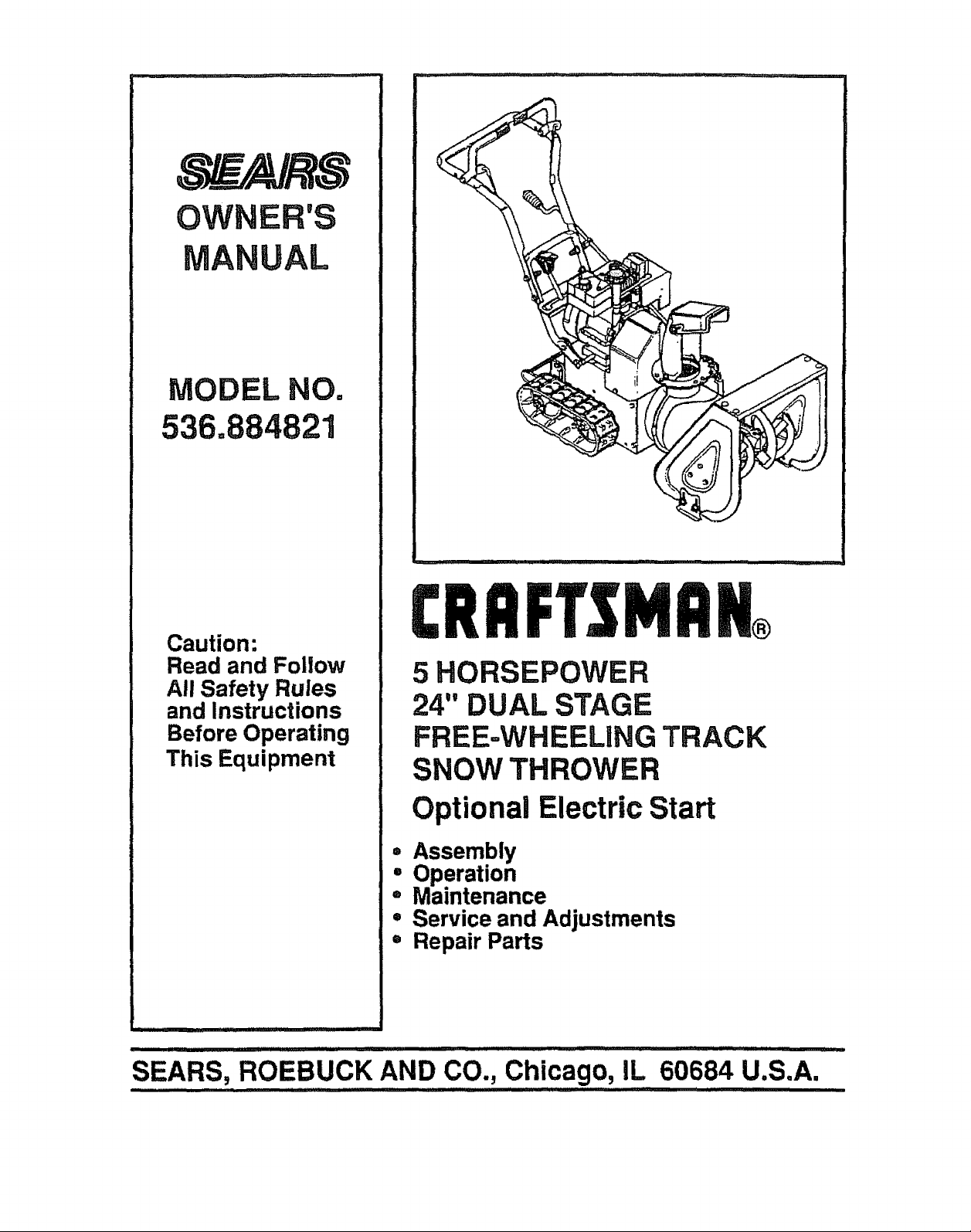
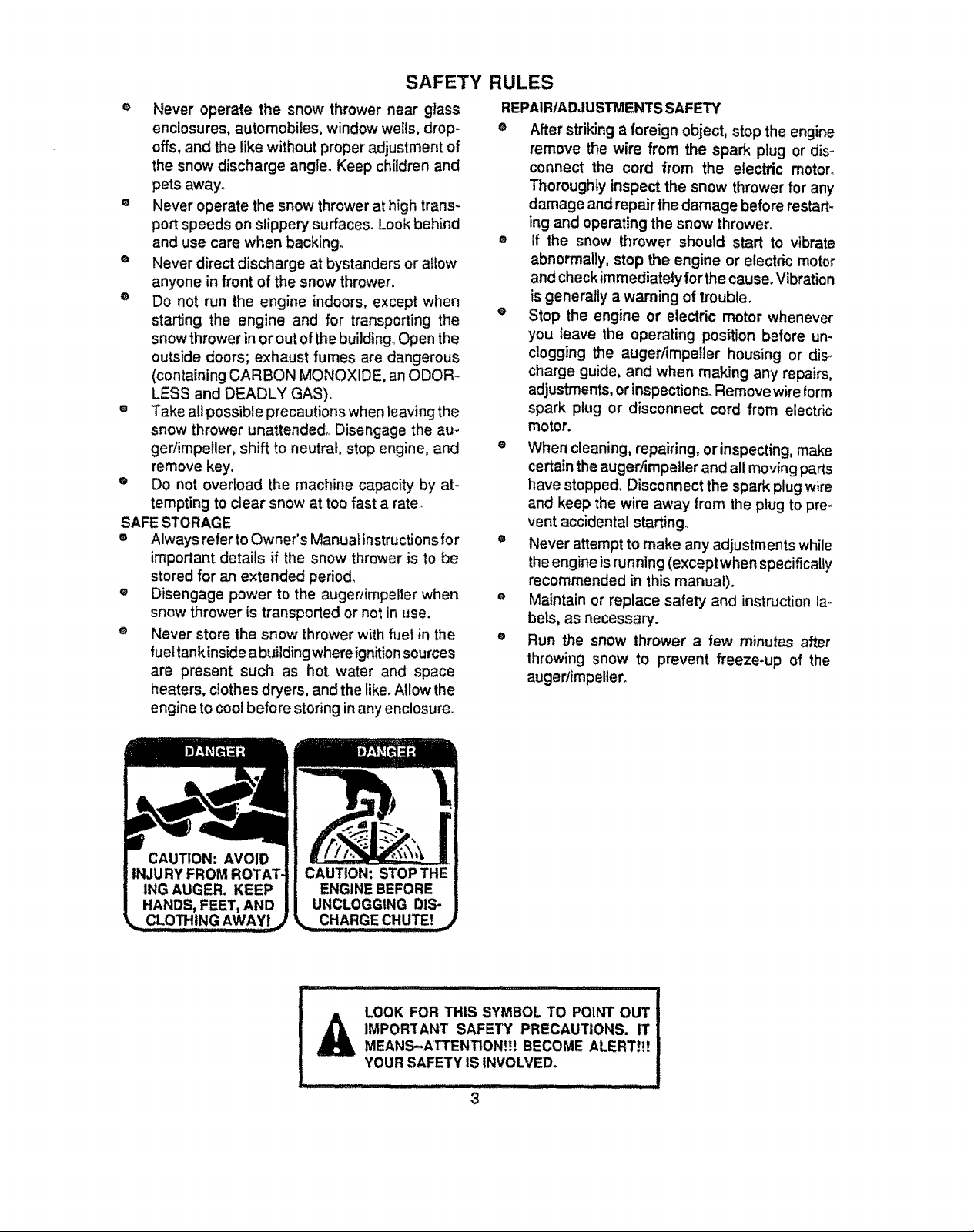
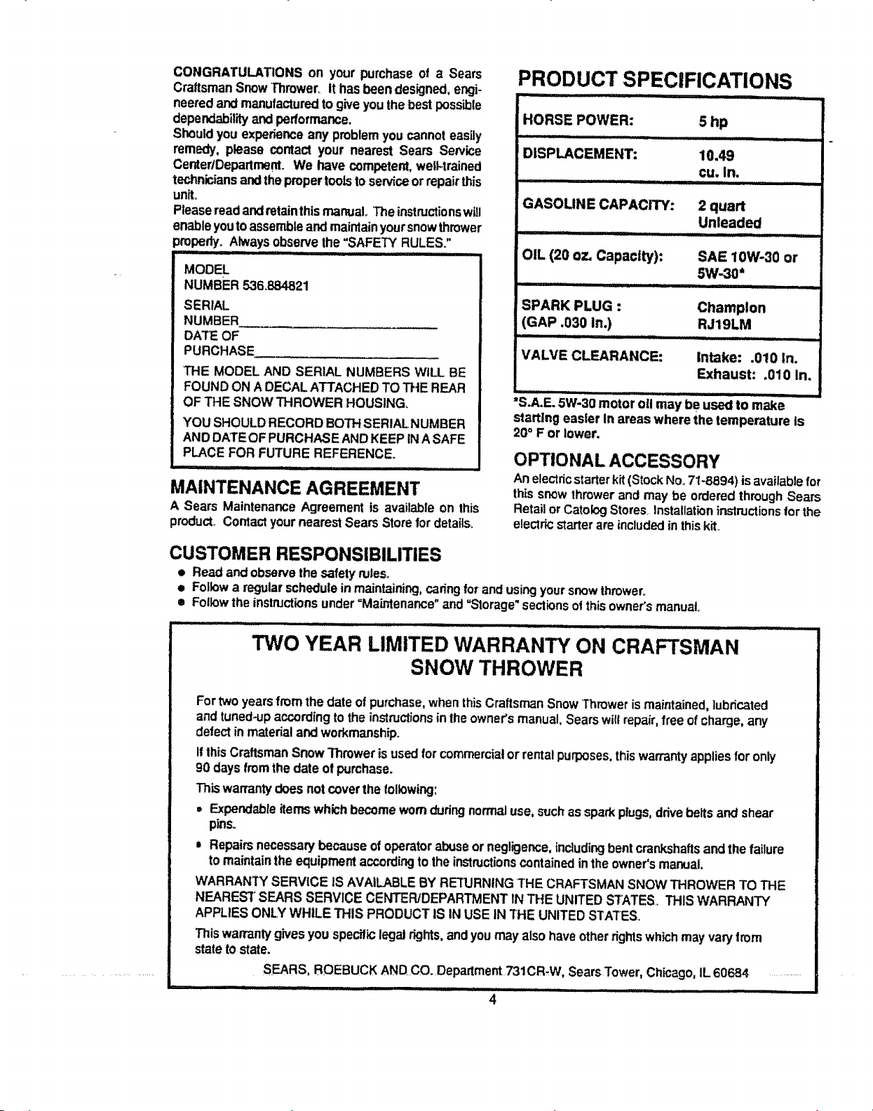
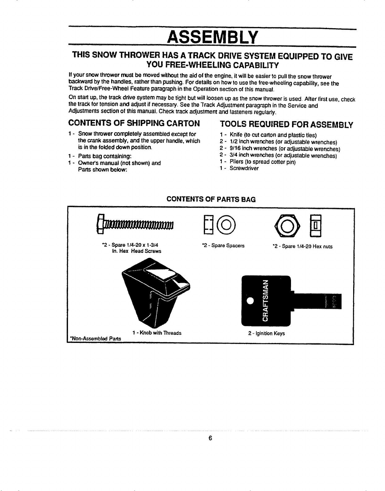
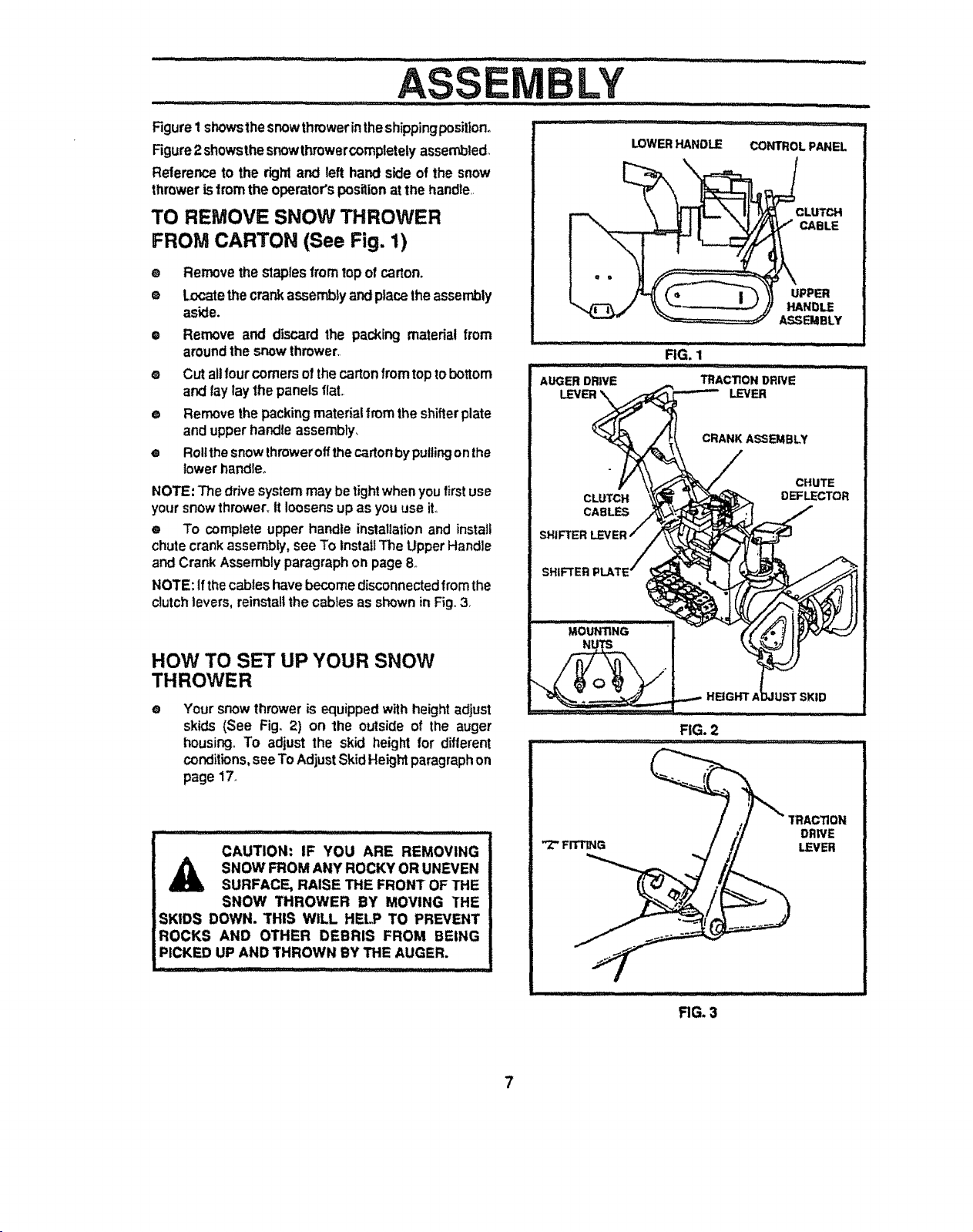
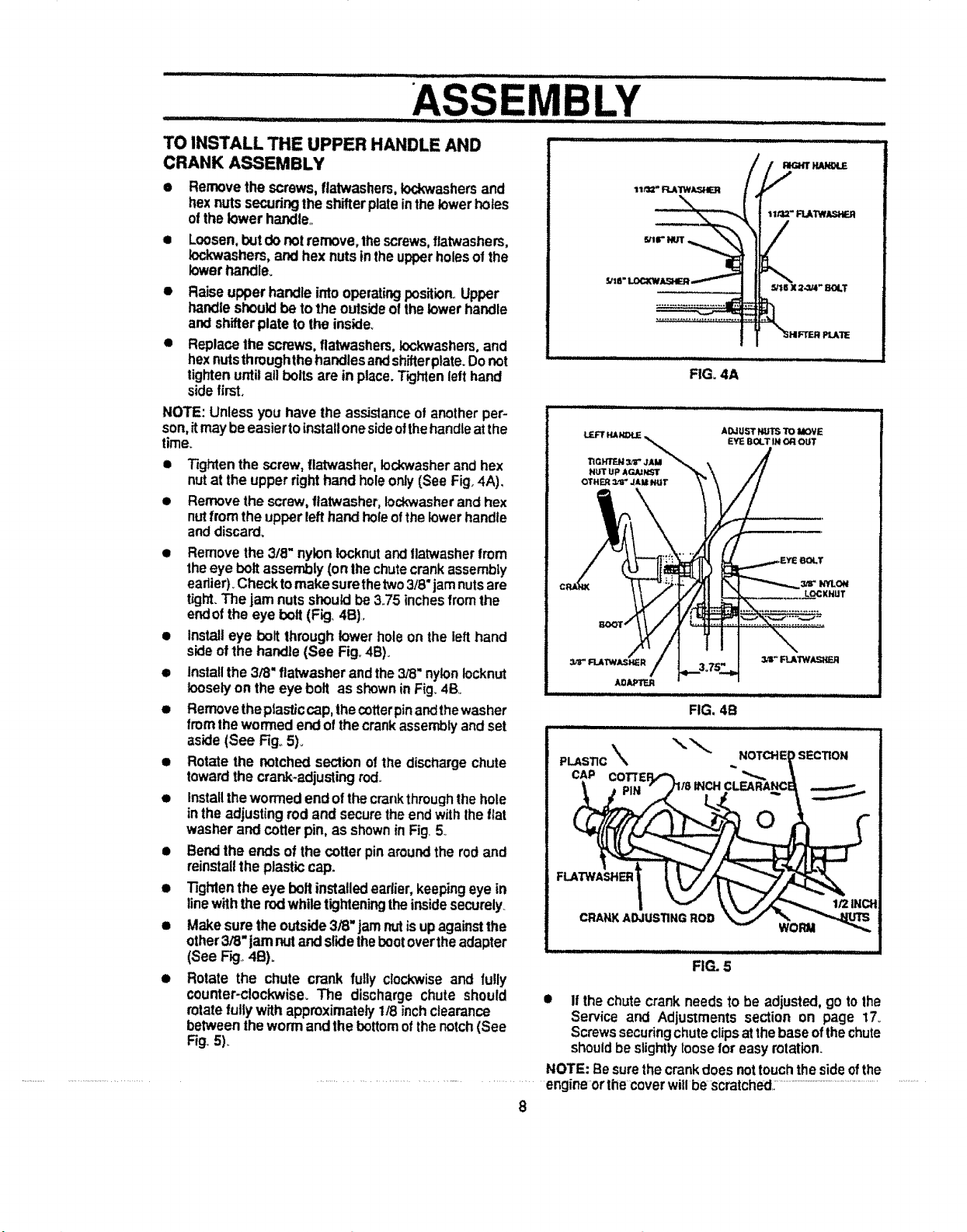
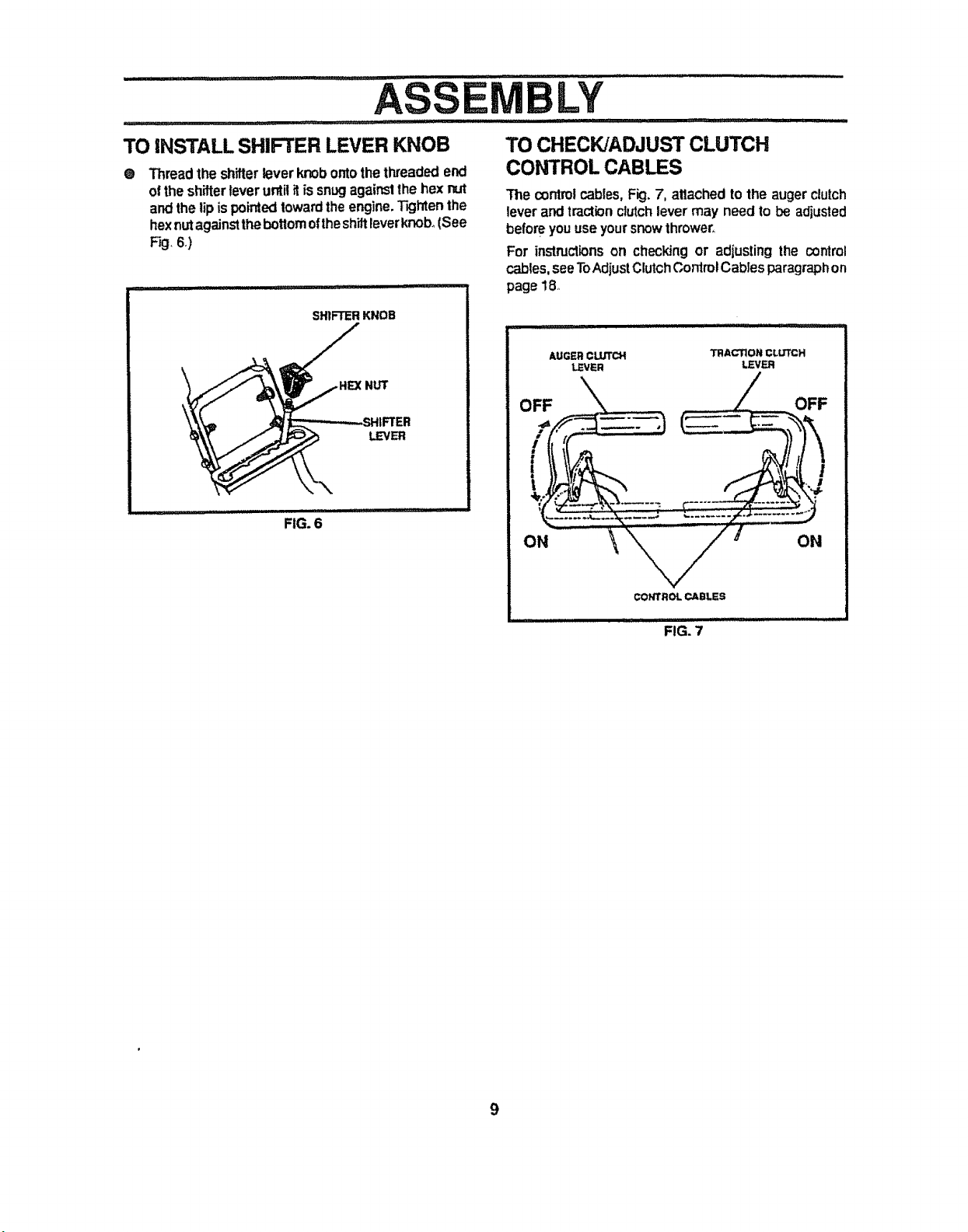
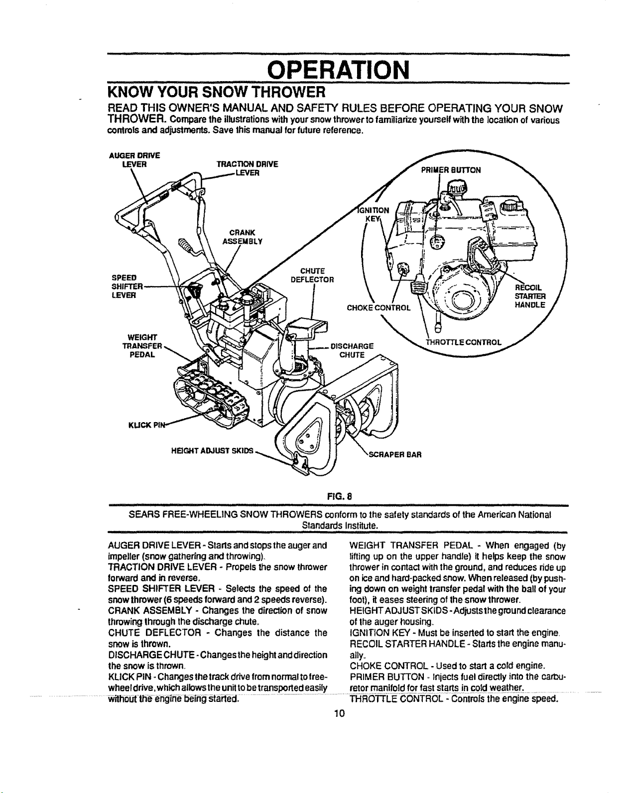
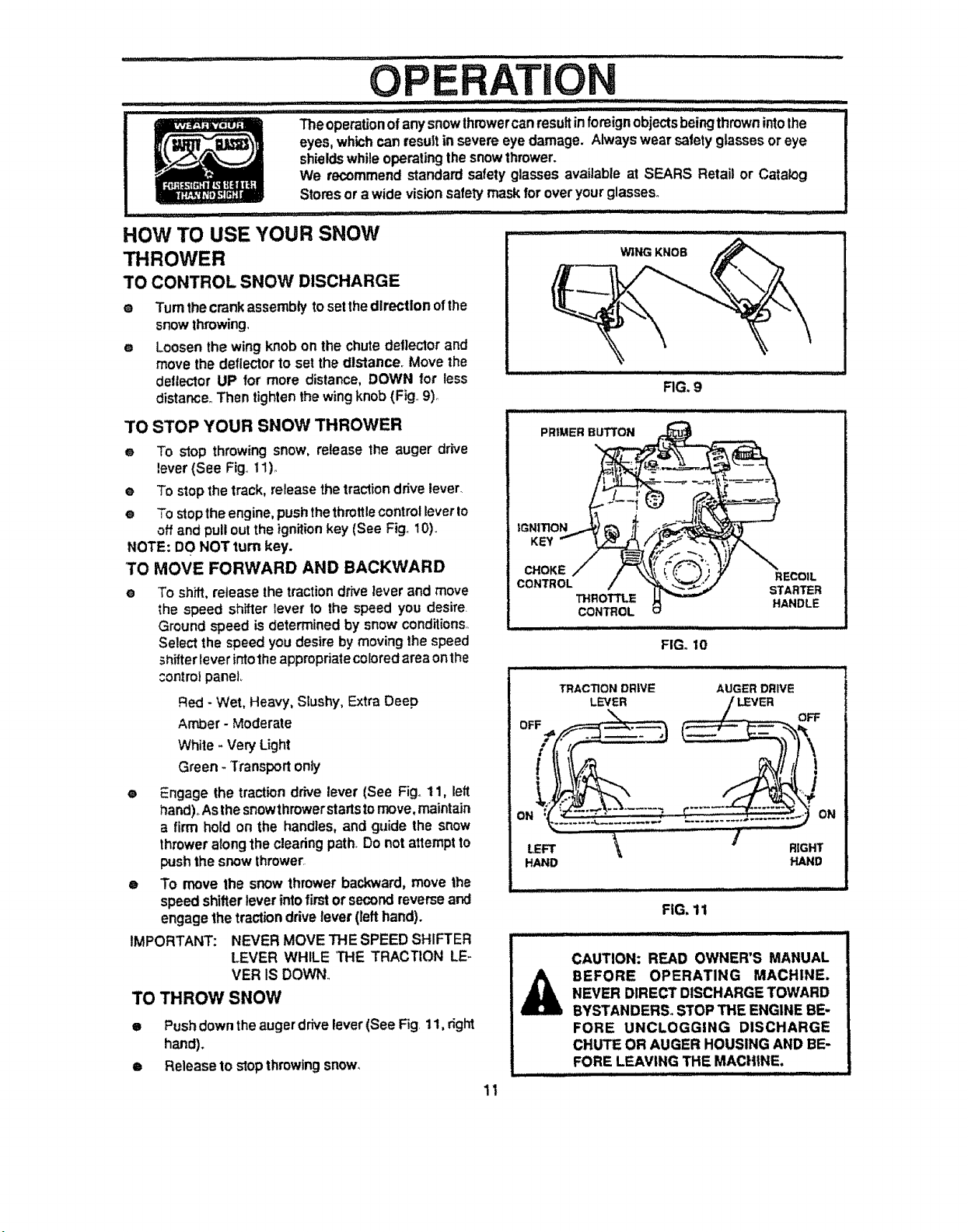
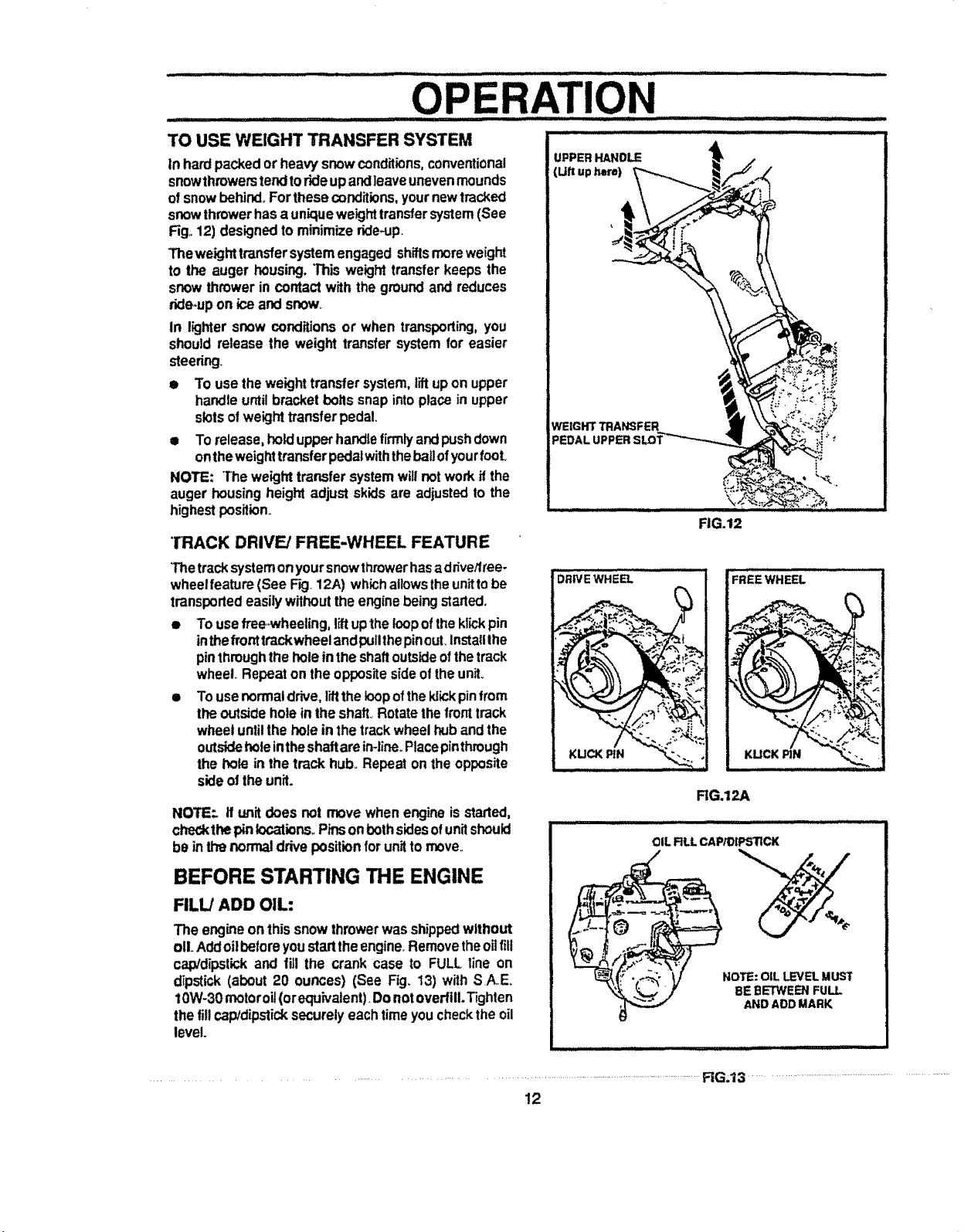
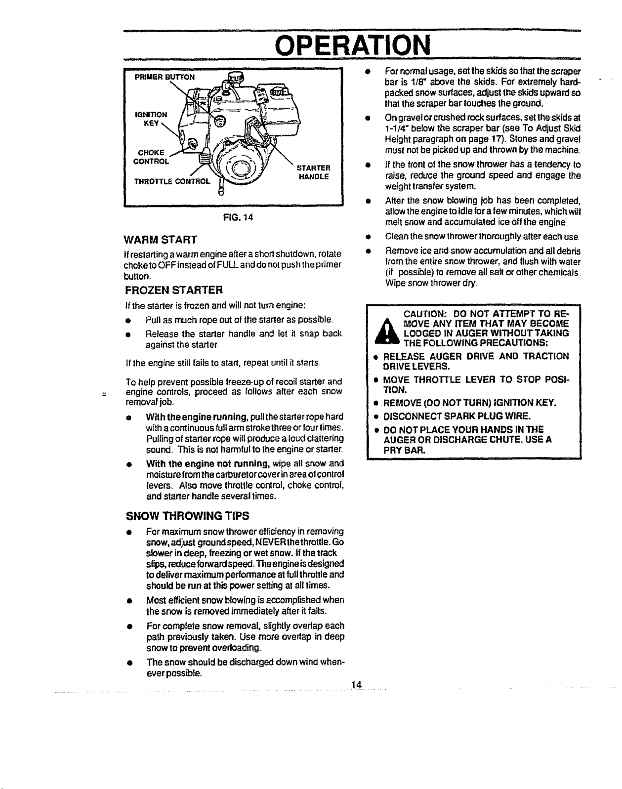


 Loading...