

Sears 536.270212 Owner's Manual
owner’s
manual
Model No.
536.270212
CAUTION:
Read And Follow
All Safety Rules
And Instructions
Before Operating
This Equipment.
To Call Toll Free
For Service
1–800–4–REPAIR
(1–800–473–7247)
13.5 HP. ELECTRIC START
30” MOWER / MULCHER
5 SPEED
REAR ENGINE RIDER
Assembly
For Parts
Operation
1–800–366–PART
Customer Responsibilities
(1–800–366–7278)
Service And Adjustment
F–000614J Sears, Roebuck and Co., Hoffman Estates, IL. 60179 U.S.A.
Printed in U.S.A.

TABLE OF CONTENTS
WARRANTY 2. . . . . . . . . . . . . . . . . . . . . . . . . . . . . . . . . . . . . . . . .
CUSTOMER RESPONSIBILITIES 3. . . . . . . . . . . . . . . . . . . . . .
PRODUCT SPECIFICATIONS 3. . . . . . . . . . . . . . . . . . . . . . . . .
SAFETY RULES 4. . . . . . . . . . . . . . . . . . . . . . . . . . . . . . . . . . . . .
RESPONSIBILITY OF THE OWNER 5. . . . . . . . . . . . . . . . . . . .
ACCESSORIES AND ATTACHMENTS 6. . . . . . . . . . . . . . . . . .
ASSEMBLY 7. . . . . . . . . . . . . . . . . . . . . . . . . . . . . . . . . . . . . . . . .
MAINTENANCE FREE BATTERY 8. . . . . . . . . . . . . . . . . . . . . . . . . .
HOW TO ASSEMBLE THE STEERING WHEEL 9. . . . . . . . . . . . . .
HOW TO ASSEMBLE THE HUB CAPS 9. . . . . . . . . . . . . . . . . . . . .
CHECK THE TIRES 9. . . . . . . . . . . . . . . . . . . . . . . . . . . . . . . . . . . . . . .
CHECK THE DRIVE BRAKE 9. . . . . . . . . . . . . . . . . . . . . . . . . . . . . . .
CHECK THE BELTS 9. . . . . . . . . . . . . . . . . . . . . . . . . . . . . . . . . . . . . .
HOW TO INSTALL THE SEAT 10. . . . . . . . . . . . . . . . . . . . . . . . . . . . .
CHECK THE LEVEL OF THE MOWER HOUSING 10. . . . . . . . . . . .
OPERATION 11. . . . . . . . . . . . . . . . . . . . . . . . . . . . . . . . . . . . . . . . .
LOCATION OF CONTROLS 11. . . . . . . . . . . . . . . . . . . . . . . . . . . . . . .
HOW TO USE THE THROTTLE CONTROL 12. . . . . . . . . . . . . . . . . .
HOW TO USE THE ATTACHMENT CLUTCH 12. . . . . . . . . . . . . . . .
HOW TO USE THE SHIFT LEVER 12. . . . . . . . . . . . . . . . . . . . . . . . . .
HOW TO SET THE PARKING BRAKE 13. . . . . . . . . . . . . . . . . . . . . .
HOW TO CHANGE THE CUTTING HEIGHT 13. . . . . . . . . . . . . . . . .
HOW TO STOP THE UNIT 13. . . . . . . . . . . . . . . . . . . . . . . . . . . . . . . . .
HOW TO TRANSPORT THE UNIT 13. . . . . . . . . . . . . . . . . . . . . . . . . .
HOW TO OPERATE WITH THE MOWER HOUSING 14. . . . . . . . . .
HOW TO OPERATE THE UNIT ON HILLS 14. . . . . . . . . . . . . . . . . . .
BEFORE STARTING THE ENGINE 15. . . . . . . . . . . . . . . . . . . . . . . . .
HOW TO START THE ENGINE 15. . . . . . . . . . . . . . . . . . . . . . . . . . . . .
HOW TO START WITH A WEAK BATTERY 15. . . . . . . . . . . . . . . . .
HOW TO CHANGE THE MULCHER PLATE 16. . . . . . . . . . . . . . . . .
OPERATING TIPS 17. . . . . . . . . . . . . . . . . . . . . . . . . . . . . . . . . . . . . . . .
MOWING AND BAGGING TIPS 17. . . . . . . . . . . . . . . . . . . . . . . . . . . .
MULCHING TIPS 17. . . . . . . . . . . . . . . . . . . . . . . . . . . . . . . . . . . . . . . . .
CUSTOMER RESPONSIBILITIES 18. . . . . . . . . . . . . . . . . . . . . .
MAINTENANCE CHART 18. . . . . . . . . . . . . . . . . . . . . . . . . . . . . . . . . .
CHECK THE TIRES 18. . . . . . . . . . . . . . . . . . . . . . . . . . . . . . . . . . . . . . .
HOW TO REMOVE AND INSTALL THE BLADE 19. . . . . . . . . . . . . .
HOW TO SHARPEN THE BLADE 19. . . . . . . . . . . . . . . . . . . . . . . . . .
HOW TO ADJUST THE ATTACHMENT CLUTCH 20. . . . . . . . . . . . .
HOW TO CHECK AND ADJUST THE DRIVE BRAKE 21. . . . . . . . .
HOW TO CHECK AND ADJUST THE CLUTCH 21. . . . . . . . . . . . . .
HOW TO REMOVE THE SIDE PANEL 22. . . . . . . . . . . . . . . . . . . . . .
BATTERY SERVICE 22. . . . . . . . . . . . . . . . . . . . . . . . . . . . . . . . . . . . . .
HOW TO CHARGE THE BATTERY 22. . . . . . . . . . . . . . . . . . . . . . . . .
WHERE TO LUBRICATE 23. . . . . . . . . . . . . . . . . . . . . . . . . . . . . . . . . .
HOW TO CHECK THE OIL 24. . . . . . . . . . . . . . . . . . . . . . . . . . . . . . . .
HOW TO CHANGE THE OIL 24. . . . . . . . . . . . . . . . . . . . . . . . . . . . . . .
HOW TO CLEAN THE COOLING SYSTEM 24. . . . . . . . . . . . . . . . . .
HOW TO CHECK THE MUFFLER 24. . . . . . . . . . . . . . . . . . . . . . . . . .
HOW TO CLEAN THE AIR FILTERS 25. . . . . . . . . . . . . . . . . . . . . . . .
HOW TO CHECK THE SPARK PLUG 25. . . . . . . . . . . . . . . . . . . . . . .
SERVICE AND ADJUSTMENT 26. . . . . . . . . . . . . . . . . . . . . . . . .
HOW TO ADJUST THE THROTTLE CONTROL 26. . . . . . . . . . . . . .
HOW TO REMOVE THE MOWER HOUSING 27. . . . . . . . . . . . . . . .
HOW TO INSTALL THE MOWER HOUSING 27. . . . . . . . . . . . . . . . .
HOW TO LEVEL THE MOWER HOUSING 28. . . . . . . . . . . . . . . . . . .
HOW TO REPLACE THE MOTION DRIVE BELT 29. . . . . . . . . . . . .
HOW TO REPLACE THE MOWER DRIVE BELT 30. . . . . . . . . . . . .
HOW TO REPLACE THE FUSE 31. . . . . . . . . . . . . . . . . . . . . . . . . . . .
HOW TO SET THE CUTTING HEIGHT 31. . . . . . . . . . . . . . . . . . . . . .
HOW TO CLEAN THE MOWER HOUSING 31. . . . . . . . . . . . . . . . . .
FRONT WHEEL ALIGNMENT 31. . . . . . . . . . . . . . . . . . . . . . . . . . . . . .
STORAGE (OVER 30 DAYS) 32. . . . . . . . . . . . . . . . . . . . . . . . . . . . . . .
TROUBLE SHOOTING CHART 33. . . . . . . . . . . . . . . . . . . . . . . .
SLOPE GUIDE 34. . . . . . . . . . . . . . . . . . . . . . . . . . . . . . . . . . . . . . .
INDEX 35. . . . . . . . . . . . . . . . . . . . . . . . . . . . . . . . . . . . . . . . . . . . . .
REPAIR PARTS 36. . . . . . . . . . . . . . . . . . . . . . . . . . . . . . . . . . . . . .
LIMITED WARRANTY ON CRAFTSMAN EQUIPMENT PARTS
For two (2) years from the date of purchase, if this Craftsman Equipment is maintained, lubricated and tuned up according to
the instructions in the owner’s manual, Sears will repair or replace free of charge any parts found to be defective in material
or workmanship. Warranty service is available free of charge by taking your Craftsman equipment to your nearest Sears Service
Center. In–home warranty service is available but a trip charge will apply. This Warranty applies only while this product is in
the United States.
This Warranty does not cover:
Expendable items which become worn during normal use, such as blades, spark plugs, air cleaners, belts, and oil filters.
Tire replacement or repair caused by punctures from outside objects, such as nails, thorns, stumps or glass.
Repairs necessary because of operator abuse, including but not limited to, damage caused by towing objects beyond the
capability of the equipment, impacting objects that bend the frame or crankshaft, or over–speeding the engine.
Repairs necessary because of operator negligence, including but not limited to, electrical and mechanical damage caused
by improper storage, failure to use the proper grade and amount of engine oil, failure to keep the deck clear of flammable
debris, or failure to maintain the equipment according to the instructions contained in the owner’s manual.
Engine (fuel system) cleaning or repairs caused by fuel determined to be contaminated or oxidized (stale). In general, fuel
should be used within 30 days of its purchase date.
Equipment used for commercial or rental purposes.
LIMITED WARRANTY ON BATTERY
For ninety (90) days from date of purchase, if any battery is included with the equipment proves defective in material or
workmanship and our testing determines the battery will not hold a charge, Sears will replace the battery at no charge. Warranty
service is available free of charge by taking your Craftsman equipment to your nearest Sears Service Center . In–home warranty
service is available but a trip charge will apply. This Warranty applies only while this product is in the United States.
TO LOCATE THE NEAREST SEARS SERVICE CENTER OR TO SCHEDULE SERVICE, SIMPLY CONTACT SEARS AT
1–800–488–1222.
This warranty gives you specific legal rights, and you may also have other rights, which vary, from state to state.
F–000614J
2

Congratulations on your purchase of a Sears Rider. It has been
designed, engineered and manufactured to give you the best
possible dependability and performance.
If you experience any problems you cannot easily remedy, please
see your nearest Sears Service Department. We have competent,
well trained technicians and the proper tools to service or repair this
unit.
Please read and keep this manual. The instructions will enable you
to assemble and maintain your unit properly. Always observe the
“Safety Rules”.
CUSTOMER RESPONSIBILITIES
NOTE: This unit is equipped with an internal combustion engine and
must not be used on or near any unimproved forest–covered,
brush–covered or grass–covered land unless the engine’s exhaust
system is equipped with a spark arrester meeting applicable local
or state laws (if any). If a spark arrester is used, it must be
maintained in effective working order by the operator.
In the State of California, the above is required by law (Section 4442
of the California Public Resources Code). Other states may have
similar laws. Federal laws apply on federal lands. See an Authorized
Service Center for a spark arrester for the muffler.
Carefully read and follow the rules for safe operation. Inspect
the unit.
Follow all the assembly instructions. Carefully adjust the unit.
Know how to operate all standard and accessary equipment on
the unit. Make sure the operator can correctly operate the unit.
Operate the unit only with guards, shields and other safety
items in place and working correctly.
Complete all maintenance on the unit. Service the unit only with
authorized or approved replacement parts.
See the Maintenance Chart.
PRODUCT SPECIFICATIONS
Engine 13.5 HP.. . . . . . . . . . . . . . . . . .
Charging System 3 amperes at 3600 rpm. . . . . . . . .
Fuel Tank SIze 1 gallon. . . . . . . . . . .
Type of Fuel Unleaded Regular. . . . . . . . . . . . .
Oil Capacity 32 ounces (1 quart). . . . . . . . . . . . . .
Oil Type Above 32 degrees SAE 30. . . . . . . . . . . . . . . . .
Below 32 degrees SAE 5W30. . . . . . . . . . . . . . . . . . . . . . . . . .
Spark Plug (Gap 0.030”) Champion RJ4C. .
Tire Air Pressure Front 22 psi (See tire sidewall). . . . . . . . .
Tire Air Pressure Rear 14 psi (See tire sidewall). . . . . . . . .
All Gear Transaxle 5 forward speeds and 1 reverse. . . . . . . .
Ground Speed Range Forward 4.3 mph. . . . .
Reverse 2.1 mph. . . . . . . . . . . . . . . . . . . . . . . . . .
Tilt Seat Tilts forward to access the battery.. . . . . . . . . . . . . . . . .
Mower Housing Full-floating suspension, one blade.. . . . . . . . . .
1
Cutting Height 8 positions from 1
Blade Nut Torque 30 foot–pounds (ft–lbs). . . . . . . . .
F–000614J
/2 to 4 inches.. . . . . . . . . . .
The engine exhaust from this product
contains chemicals known to the State
of California to cause cancer, birth
defects or other reproductive harm.
MAINTENANCE AGREEMENT
A Sears Maintenance Agreement is available on this unit. See the
nearest Sears Store for information.
Rear Engine Rider
Record in the space below the serial number and the date
of purchase of this unit.
The model number and serial number are found on a decal
attached to the rear of the frame.
Model Number: 536.270212
Serial Number:
Date of Purchase:
Keep these numbers for future reference.
3

OWNER’S INFORMATION
SAFETY RULES
Safe Operation Practices for Ride–on Mowers
WARNING: This cutting machine is capable of amputating hands and feet and throwing objects. Failure to observe the
following safety instructions could result in serious injury or death.
I. General operation
1. Read, understand and follow all instructions in the Instruction Book, on the machine, the engine and with any attachments before starting.
2. Only allow responsible adults, who are familiar with the instructions, to operate the machine.
3. Clear the area of objects such as rocks, toys, wire, etc., which could be picked up and thrown by the blade.
4. Be sure the area is clear of other people before mowing. Stop the machine if anyone enters the area.
5. Never carry passengers.
6. Turn off power to the blades or any attachments before backing up. Do not mow in reverse unless absolutely necessary. Always look
down and behind before and while backing.
7. Be aware of the mower discharge direction and do not point it at anyone. Do not operate the mower without either the entire grass bagger
or the mower guard in place.
8. Slow down before turning.
9. Never leave a machine unattended with the engine running. Always turn off the blade(s), set the parking brake, stop the engine and
remove the key before dismounting.
10. Turn off power to attachment(s) when transporting or not in use. Turn off the blade(s) when not mowing.
11. Stop the engine before removing the grass bagger or unclogging the chute.
12. Mow only in daylight or good artificial light.
13. Do not operate the machine while under the influence of alcohol or drugs or when very tired.
14. Watch for traffic when operating near or crossing roadways.
15. Use extra caution when loading or unloading the machine into a trailer or truck.
16. Disengage all attachment clutches and shift into Neutral before attempting to start the engine.
17. Always wear goggles, safety glasses, or an eye shield when you operate the unit to protect your eyes from foreign objects that can be
thrown from the unit. Always wear eye protection when you make an adjustment or repair to the machine.
18. Use care when pulling loads or using heavy equipment.
a. Use only approved drawbar hitch points.
b. Limit loads to those you can safely control.
c. Do not turn sharply. Use care when backing.
d. Use counterweights or wheel weights when suggested in the Instruction Book.
19. Do not operate this machine if you are taking drugs or other medication which can cause drowsiness or affect your ability to operate
this machine.
20. Do not use this machine if you are mentally or physically unable to operate this machine safely .
21. Data indicates that operators, age 60 years and above, are involved in a large percentage of riding mower related injuries. These operators should evaluate their ability to operate a riding mower safely enough to protect themselves and others from serious injury.
II. Slope operation
Slopes and rough terrain are major factors related to loss–of–control and tip–over accidents, which can result in severe injury
or death. ALL slopes require extra caution. If you cannot back up the slope or if you feel uneasy on the slope, do not mow it. See
the “Slope Guide” in the back of this book to check for safe operation.
DO
1. Mow up and down slopes, not across.
2. Remove obstacles such as rocks, limbs, etc...
3. Watch for holes, ruts or bumps. Uneven terrain could overturn the machine.
4. Follow the manufacturer’s recommendations for wheel weights or counterweights to improve stability.
5. Use extra care with grass baggers or other attachments, they can change the stability of the machine.
6. Keep all movement on the slopes slow and gradual. Do not make sudden changes in speed or direction.
7. Avoid starting or stopping on a slope. If tires lose traction, turn off the blades and proceed slowly
DO NOT
1. Do not turn on slopes unless absolutely necessary, then only turn slowly and gradually downhill, if possible.
2. Do not mow drop–offs, ditches or embankments. A wheel over the edge or an edge caving in could cause a sudden overturn and an
injury or death.
3. Do not mow on wet grass. Reduced traction could cause sliding.
4. Do not try to stabilize the machine by putting your foot on the ground.
5. Do not use a grass bagger or other rear mounted accessories on steep slopes (greater than 10 degrees).
F–000614J
4
Tall grass can hide obstacles.
straight
down the slope.

OWNER’S INFORMATION
III. Children
Tragic accidents can occur if the operator is not alert to the presence of children. Children are often attracted to the machine and
the mowing activity. NEVER assume that children will remain where you last saw them.
1. Keep children out of the mowing area and in the watchful care of another responsible adult.
2. Be alert and turn the engine off if children enter the area.
3. Before and when backing, look behind and down for small children.
4. Never carry children or any passengers, even with the blades off. They may fall off and be seriously injured or interfere with the safe
operation of the machine.
5. Never allow children to operate the machine. Instruct children in the potential dangers of the machine.
6. Use extra care when approaching blind corners, shrubs, trees or other objects that may obscure vision.
IV. Service
1. Use extra care when handling gasoline and other fuels. Fuels are flammable and the vapors are explosive.
a. Use only an approved container.
b. Never remove the gas cap or add fuel with the engine running. Allow the engine to cool for several minutes before refueling. Do
not smoke.
c. Never refuel the machine indoors.
d. Never store the machine with fuel in the tank or fuel container inside where there is an open flame, such as a water heater.
2. Never start or run the engine inside a closed area.
3. Keep all nuts and bolts, especially the blade attachment nuts tight. Frequently check the blade(s) for wear or damage such as cracks
and nicks. A blade that is bent or damaged must be immediately replaced with an original equipment blade from an authorized service
dealer. For safety, replace the blade every two years. Keep the equipment in good condition.
4. Never tamper with the safety devices. Check their proper operation regularly.
5. To reduce fire hazards, keep the machine free of grass, leaves or other debris build–up. Clean up oil or fuel spills. Allow the machine
to cool before storing.
6. Stop and inspect the equipment if you strike an object. Repair, if necessary, before restarting.
7. Never make adjustments or repairs with the engine running. The carburetor can be adjusted with the engine running. Do not change
the engine governor settings or over–speed the engine.
8. Grass bagger components are subject to wear, damage and deterioration, which could expose moving parts or allow objects to be
thrown. For storage, always make sure the grass bag is empty. Frequently check components and replace with manufacturer’s recommended parts when necessary.
9. Mower blade(s) are sharp and can cut. Wrap the blade(s) or wear gloves and use extra caution when servicing them or the blade housing
area.
10. Check the brake operation frequently. Adjust and service as required.
11. Wait for all movement to stop before servicing any part of the unit.
RESPONSIBILITY OF THE OWNER
Environmental Awareness
Do not fill the engine’s fuel tank completely full.
Drain fuel for off–season storage.
Use only unleaded gasoline.
Service the air cleaner regularly.
Change oil regularly. Use 30W oil in summer.
Tune–up the engine regularly.
Keep equipment in efficient operating condition.
Dispose of used engine oil properly.
Look for this symbol to indicate important safety
precautions. This symbol indicates: “Attention!
Become Alert! Your Safety Is At Risk.”
F–000614J
5
ACCESSORIES AND ATTACHMENTS
ACCESSORIES AND ATTACHMENTS
These accessories and attachments were available when the unit was purchased. They are also available at most Sears retail outlets,
catalog and service centers. Most Sears stores can order these items for you when you provide the model number of your riding mower.
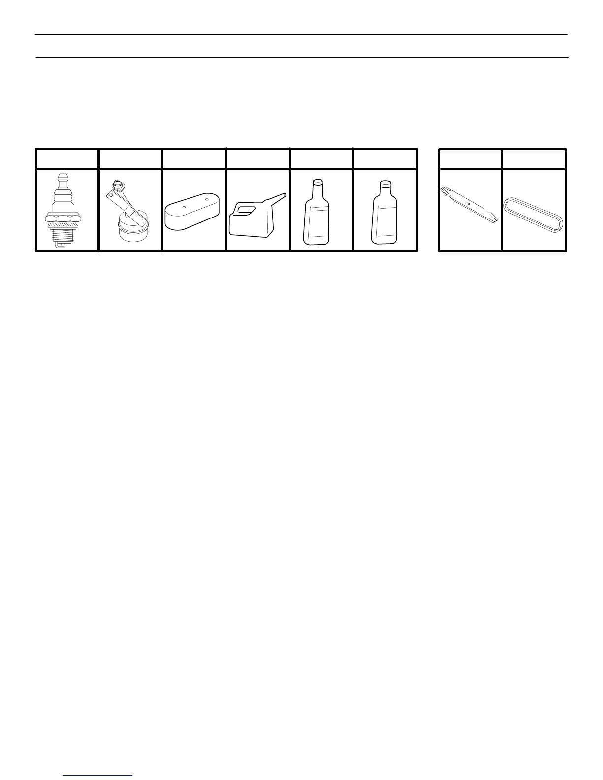
ENGINE MAINTENANCE
SPARK PLUG MUFFLER AIR FILTER GAS CAN ENGINE OIL STABILIZER BLADES BELTS
PERFORMANCE
Sears offers a wide variety of attachments that fit your riding mower. Many of these are listed below with brief explanations of how they can
help you. This list was current at the time of publication; however , it may change in future years – more attachments may be added, changes
may be mode in these attachments, or some may no longer be available or fit your model. Contact your nearest Sears store for the
accessories and attachments that are available for your unit.
Most of these attachments do not require additional hitches or conversion kits (those that do are indicated) and are designed for easy
attaching and detaching.
GRASS BAGGER lets you collect grass clippings and leaves for a
healthier, neater looking lawn. Two Grass containers hold 33 gallon
disposable plastic bags and offers 7 bushel capacity.
LAWN SWEEPERS let you collect grass clippings and leaves.
LAWN VACS for powerful collection of heavy grass clippings and
leaves. W and attachment to pick up debris in hard–to–reach places.
CARTS make hauling easy. Variety of sizes available.
ROLLER for smoother lawn surface. 36–inch wide, 18–inch
diameter water–tight drum holds up to 390–lbs. of weight. Rounded
edges prevent harm to turf. Adjustable scraper automatically cleans
drum.
SPREADER/SEEDERS make seeding, fertilizing and weed killing
easy. Broadcast spreaders are also useful for granular deicers and
sand.
CORING AERA TOR takes small plugs out of soil to allow moisture
and nutrients to reach grass roots. 36–inch swath. 24 hardened
2.5–inch steel coring tips. 150–lb. weight tray.
AERATOR promotes deep root growth for a healthy lawn. Tapered
2.5–inch steel spikes mounted on 10–inch diameter disc puncture
holes in soil at close intervals to let moisture soak in. Steel weight
tray for increased penetration.
MULCH RAKE/DETHATCHER loosens soil and flips thatch and
matted leaves to lawn surface for easy pickup. Twenty spring tine
teeth. Useful to prepare bare areas for seeding. Available for front
or rear mounting.
SPRAYERS use 12–volt DC electric motor that connects to the
riding mower battery or other 12–volt source. Includes booms for
automatic spraying when pulling, and hand held wand for spot
spraying. Wand has adjustable spray pattern. For applying
herbicides, insecticides, fungicides and liquid fertilizers.
NOTE: Do not use pull–behind attachments on slopes that are greater than 10 degrees.
F–000614J
6
ASSEMBLY
PREPARATION
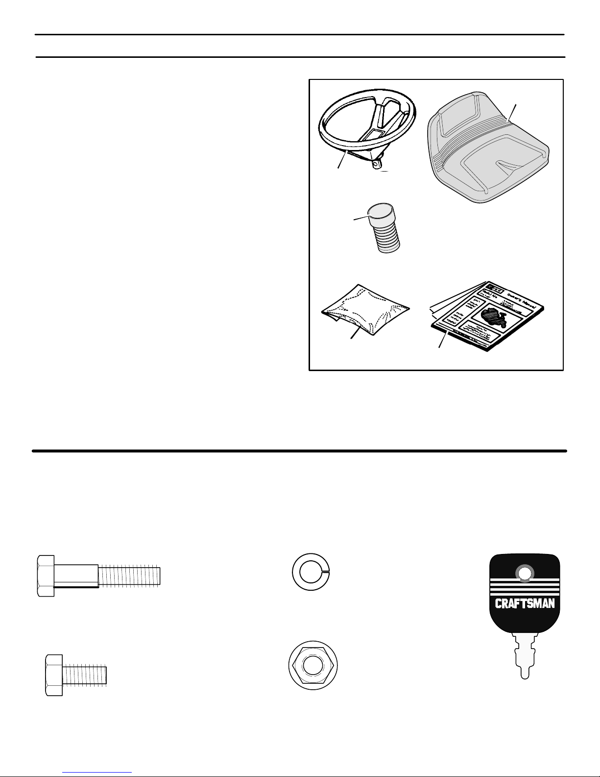
The unit is completely assembled except for the items shown in
Figure 1. These items are in the carton along with a parts bag. The
parts bag contains the fasteners needed to complete the assembly
of the unit. Find and remove these items. Do not discard any parts
or material until the unit is assembled.
HOW TO REMOVE FROM THE CARTON
To remove the unit from the carton, follow the instructions below.
1. Open the top of the carton.
2. Remove the wood frame at the top of the carton.
3. Cut each corner of the carton from the top to the bottom with a
knife. Lower the sides of the carton to the ground.
4. Move the shift lever to the neutral (N) position.
NOTE: See the Operation section, page 11, for the location
of the controls.
5. If the parking brake is engaged, completely depress the
clutch/brake pedal to release the brake.
6. Move the lift lever to the highest position.
CAUTION: Check the bottom of the carton for staples.
Remove any staples that are in the path of the tires.
7. From the front of the riding mower , carefully pull the riding mower forward off the wood frame.
Seat
Steering Wheel
Bellows
TOOLS YOU NEED TO ASSEMBLE THE UNIT
1. Adjustable wrench (2 required) 5. Phillips screwdriver
Parts Bag
Owner’s Manual
Figure 1
2. Open end wrench 1/2” –9/16” 6. Tire pressure gauge
3. Open end wrench 7/16” –1/2” 7. Knife
4. Blade type screwdriver 8. Socket Set (Optional)
MOWER PARTS BAG – CONTENTS
The fasteners and other loose parts are shown below. The fasteners are shown at full size. The quantity is shown in brackets ( ).
On some models, all of the fasteners are not required.
1x10²
(1) Hex Bolt
5/16”–18x1
STD523115
1
/2”
18x16
(2) Lockwasher
STD551131
1x45
(2) Hex Bolt
5
/16”–18x5/8”
STD523106
F–000614J
15x88
(1) Flange Nut
5/16”–18
STD541431
7
91275
(2) Ignition Key
ASSEMBLY
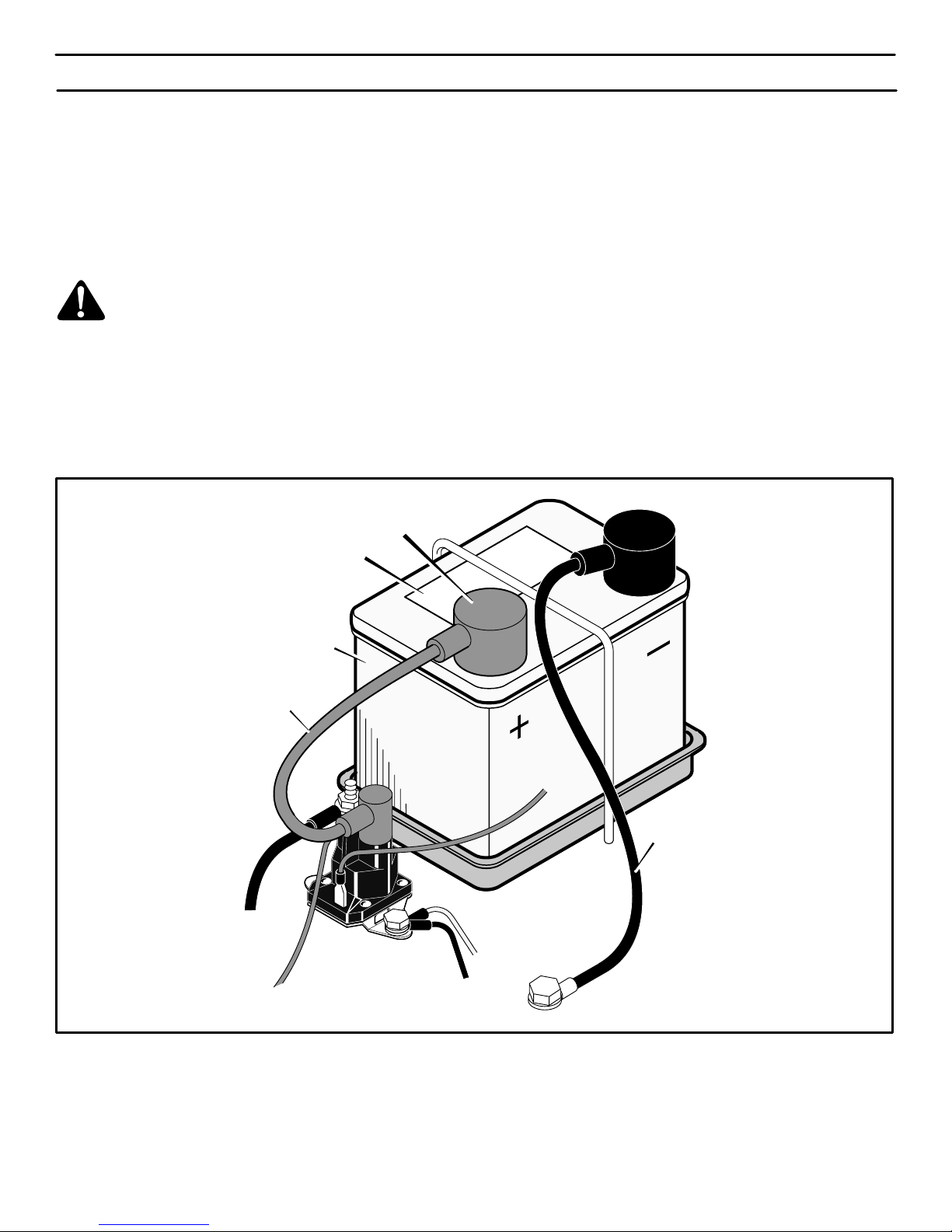
MAINTENANCE FREE BATTERY
1. Check the battery date on top of the battery (Figure 2). The
battery date tells if the battery must be charged.
2. If the battery is put into service
battery must be charged. See “How To Charge The
Maintenance Free Battery”.
after
the battery date, the
HOW TO CHARGE THE MAINTENANCE FREE BATTERY
WARNING: When you charge the battery, do not
smoke. Keep the battery away from any sparks. The
fumes from the battery acid can cause an explosion.
1. Remove the battery. See “How To Remove And Install The
Battery” in the Customer Responsibilities section.
Positive (+)
Terminal
Battery Date
2. Use a 12 volt battery charger to charge the battery. Charge at
a rate of 6 amperes for one hour. If you do not have a battery
charger, have an authorized service center charge the battery.
3. Install the battery. See “How To Remove And Install The
Battery” in the Customer Responsibilities section.
Red
Cable
Battery
Black Cable
Figure 2
F–000614J
8
ASSEMBLY
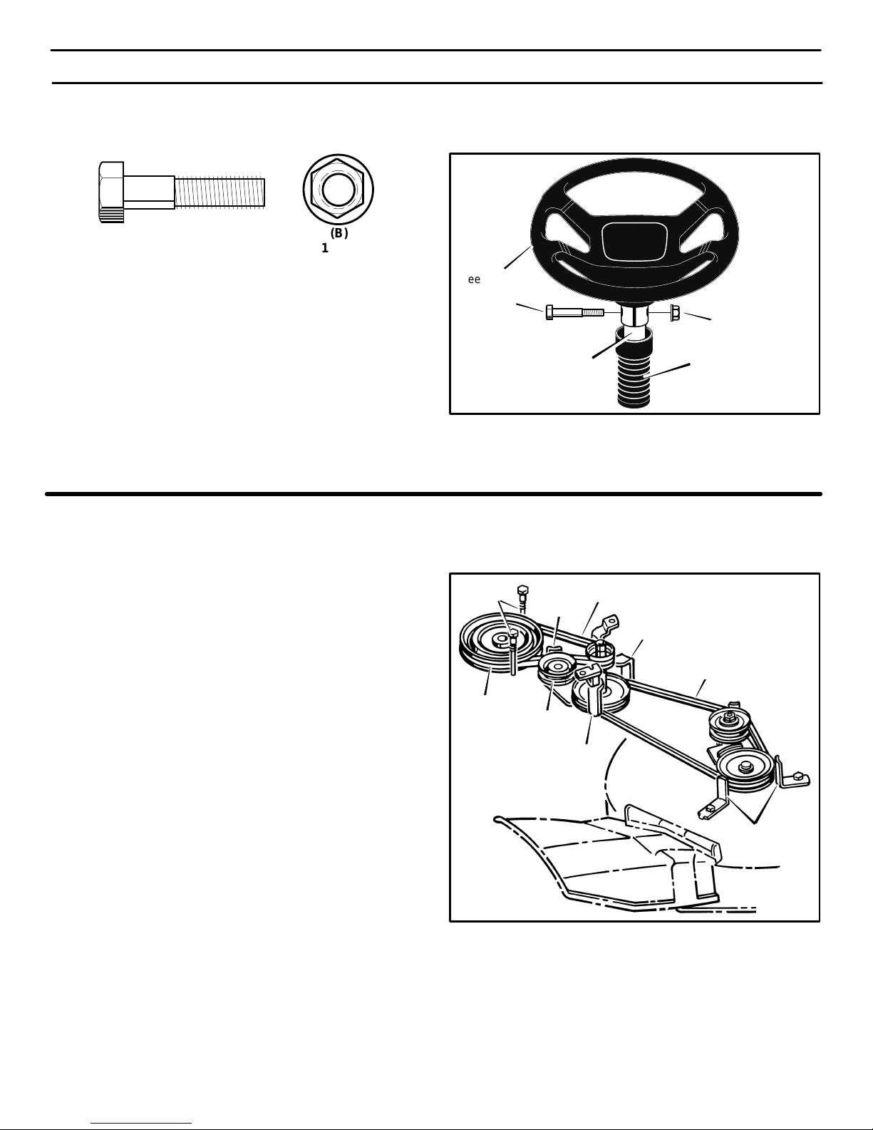
HOW TO ASSEMBLE THE STEERING WHEEL
Use the fasteners shown below to install the steering wheel. The
fasteners are shown at full size.
NOTE: Make sure the steering wheel is tight. If the steering
wheel is loose, tighten the fasteners.
(A)
1x10²
1. Make sure the front wheels point forward.
2. Some models have an
over the steering post. Make sure the collar of the bellows is
on top (Figure 3).
3. Attach the steering wheel to the steering post with the fasten-
ers. Tighten the fasteners.
optional
bellows. Slide the bellows
(B)
15x88
CHECK THE TIRES
Check the air pressure in the tires. Tires with too much air pressure
will cause the unit to ride rough. Also, the wrong air pressure will
keep the mower housing from cutting level. The correct air pressure
(PSI) is as follows.
Front Tires 22 PSI (1.5 BAR)
Rear Tires 14 PSI (1 BAR)
CHECK THE DRIVE BRAKE
The drive brake can be easily checked as follows.
1. Set the parking brake. See page 13.
2. Move the shift lever to the neutral (N) position.
3. Push the unit.
4. If the rear wheels rotate, adjust the drive brake. See “How To
Check And Adjust The Drive Brake” in the Customer
Responsibilities section.
Steering Wheel
A
Steering Post
Belt Guides
Transaxle Pulley
Idler Pulley
Motion Drive Belt
Belt Guide
Belt Guide
Belt Guide
Mower Drive Belt
B
Bellows
(Optional)
Belt Guides
Figure 3
CHECK THE BELTS
Move the lift lever to the lowest cutting height. Check the routing of
the belts. Make sure the belts are not twisted. Make sure the belts
are inside all the belt guides (Figure 4).
F–000614J
Figure 4
9
ASSEMBLY
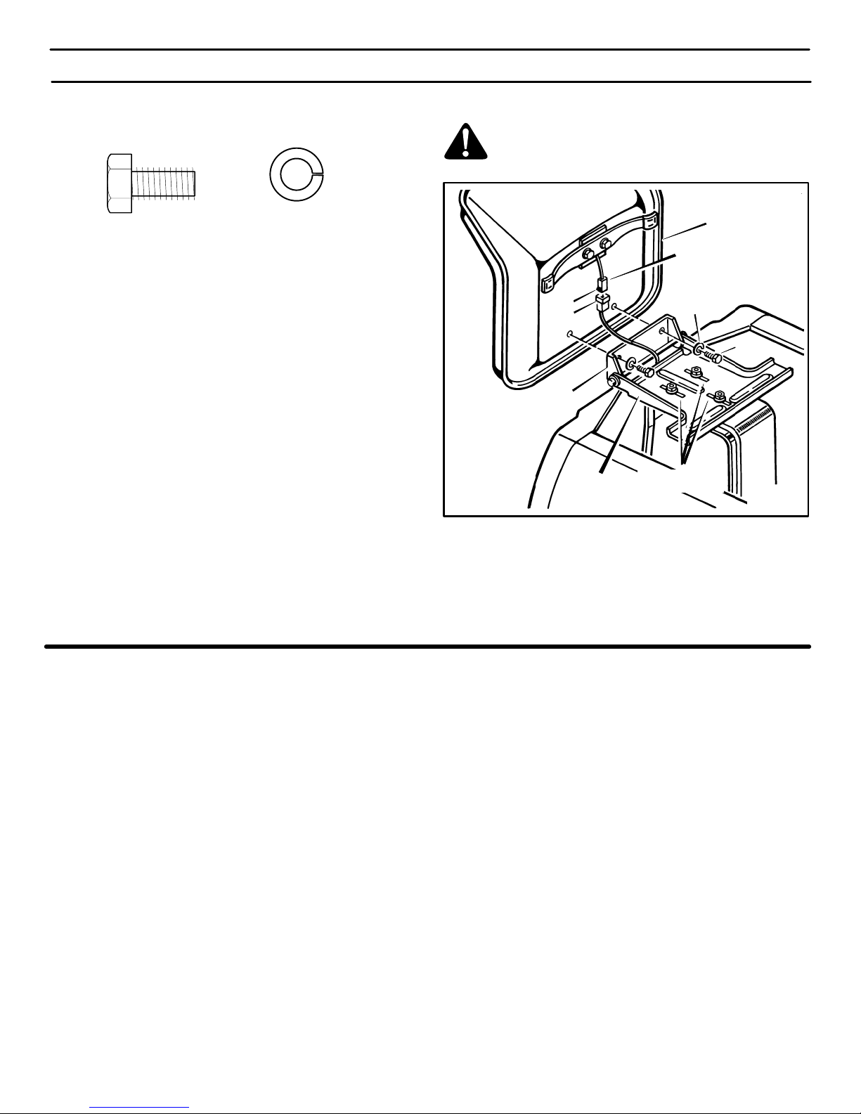
HOW TO INSTALL THE SEAT
Use the fasteners shown below to install the seat. The fasteners are
shown at full size.
WARNING: For correct and safe operation of the unit,
fasten the connector to the wire harness. If the
connector is not attached, the engine will stop when
the attachment clutch is engaged.
(A)
1x45
1. Carefully remove the protective sleeve and the plastic bag from
the seat. Do not damage the wire attached to the bottom of the
seat.
2. Pivot the seat hinge to the position shown in Figure 5.
3. Align the holes in the seat hinge to the holes in the seat
(Figure 5). Fasten the seat to the seat hinge with the fasteners
as shown. Tighten the fasteners.
4. Check the operating position of the seat. If the seat needs to
be adjusted, loosen the three nuts in the seat bracket. Slide the
seat bracket forward or backward along the seat adjusting
holes as shown. To keep the seat straight, tighten the rear nut
and then tighten the two front nuts.
5. Fasten the connector to the wire harness. Make sure the tab
on the connector locks into the wire harness.
6. Check the routing of the wire harness. Make sure the wire har-
ness is between the seat hinge and the seat bracket.
(B)
18x16
Tab
Wire
Harness
Seat Hinge
Seat
Bracket
Seat
Connector
B
A
Seat
Adjusting Holes
Figure 5
CHECK THE LEVEL OF THE MOWER HOUSING
NOTE: After the unit is fully assembled, read the Operation
section.
The level of cut was set at the factory. To check the level of cut, mow
a short distance and look at the area that was cut. If the mower
housing does not cut level, see the instructions on “How To Level
The Mower Housing” in the Service And Adjustment section of this
instruction book.
F–000614J
10
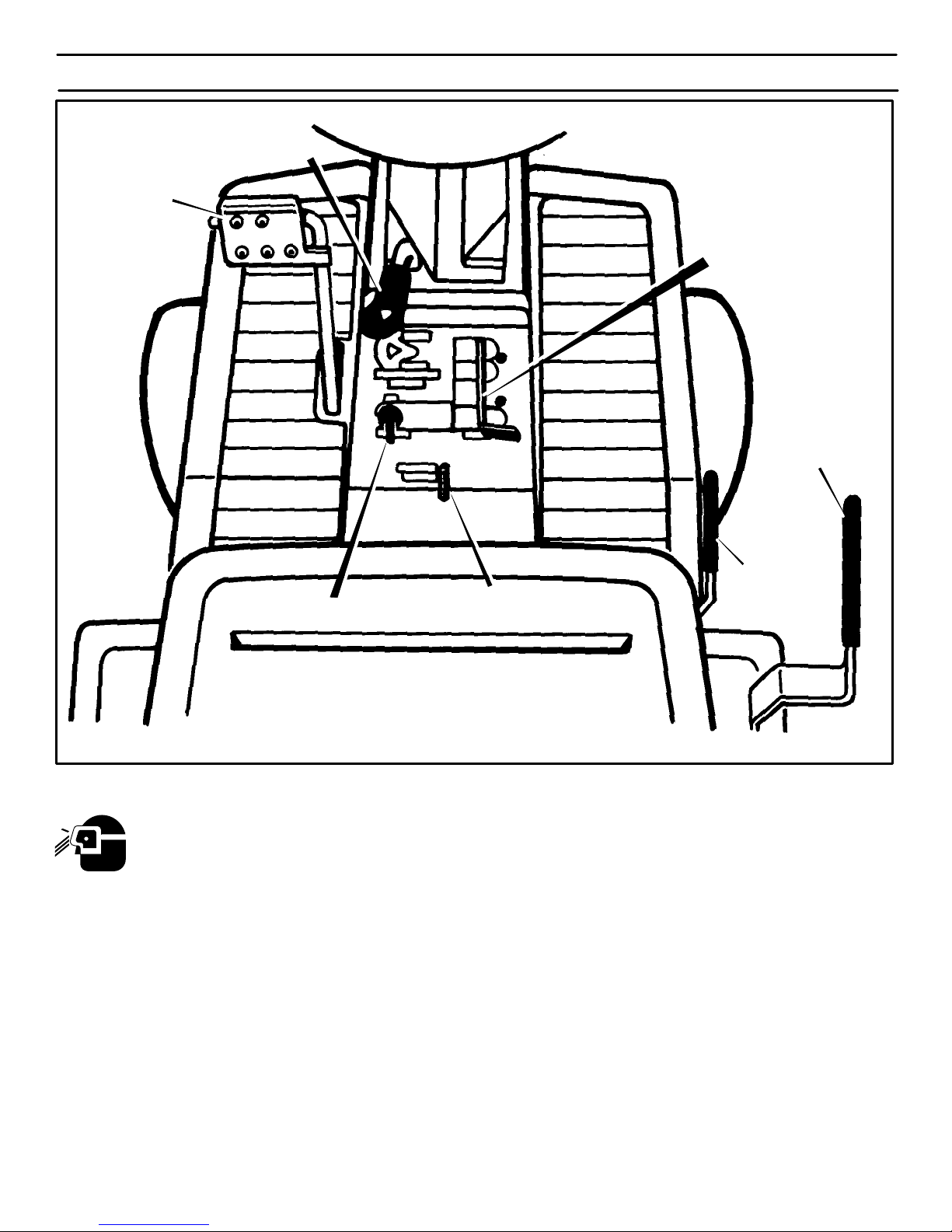
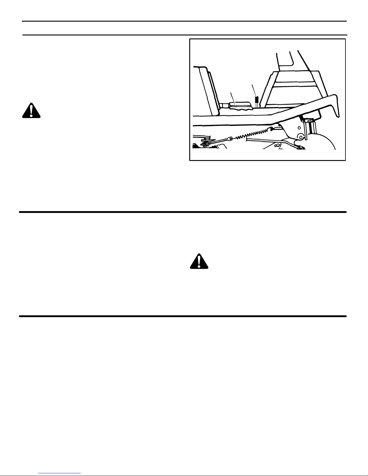
Clutch / Brake
Pedal
Attachment
Clutch
OPERATION
Throttle Control
Lever
Shift Lever
Ignition Switch
The operation of any lawn mower can result in foreign objects thrown in the eyes, which can result in severe eye
damage. Always wear safety glasses or eye shields before starting your lawn mower and while mowing. We recommend the Wide Vision Safety Mask for over the spectacles or standard safety glasses, available at Sears Retail or
Catalog Stores.
LOCATION OF CONTROLS
ATTACHMENT CLUTCH:
start and stop the rotation of the blade.
Use the attachment clutch to
CLUTCH / BRAKE PEDAL: The pedal has two functions.
The first function is a clutch. The second function is a brake.
IGNITION SWITCH: Use the ignition switch to start and stop
the engine.
Lift Lever
Parking Brake
Lever
PARKING BRAKE LEVER: Use the parking brake lever
to engage the brake when you leave the unit.
SHIFT LEVER: Use the shift lever to change the speed of the
unit.
Figure 6
LIFT LEVER: Use the lift lever to change the height of cut.
F–000614J
THROTTLE CONTROL LEVER: Use the throttle control
lever to increase or decrease the speed of the engine.
11
OPERATION
FAST
SLOW
HOW TO USE THE THROTTLE CONTROL
Use the throttle control to increase or decrease the speed of the
engine.
1. The FAST position is marked with a detent. For normal operation and when using a grass bagger , move the throttle control
to the F AST position. For maximum charging of the battery an d
also for a cooler running engine, always operate the engine in
the FAST position.
2. The engine governor is set at the factory for maximum performance. Do not adjust the governor to increase the speed of the
engine.
HOW TO USE THE ATTACHMENT CLUTCH
Note: If the engine stops when you engage the blade(s), the
seat switch is not activated. Make sure you sit in the middle of
the seat. Also, make sure the wire is connected to the seat
switch.
The attachment clutch is next to the steering wheel (Figure 7). Use
the attachment clutch to engage the blade(s).
1. Before you start the engine, make sure the attachment clutch
is in the DISENGAGE position.
2. Move the attachment clutch to the ENGAGE position to rotate the blade(s).
3. Move the attachment clutch to the DISENGAGE position to
stop the blade(s). Before you leave the operator’s position,
make sure the blade(s) has stopped rotating.
4. Before you ride the unit across a sidewalk or a road, move the
attachment clutch to the DISENGAGE position.
WARNING: Always keep your hands and feet away
from the blade, deflector opening, and the mower
housing when the engine runs.
Attachment Clutch
Engage Position
Disengage Position
Figure 7
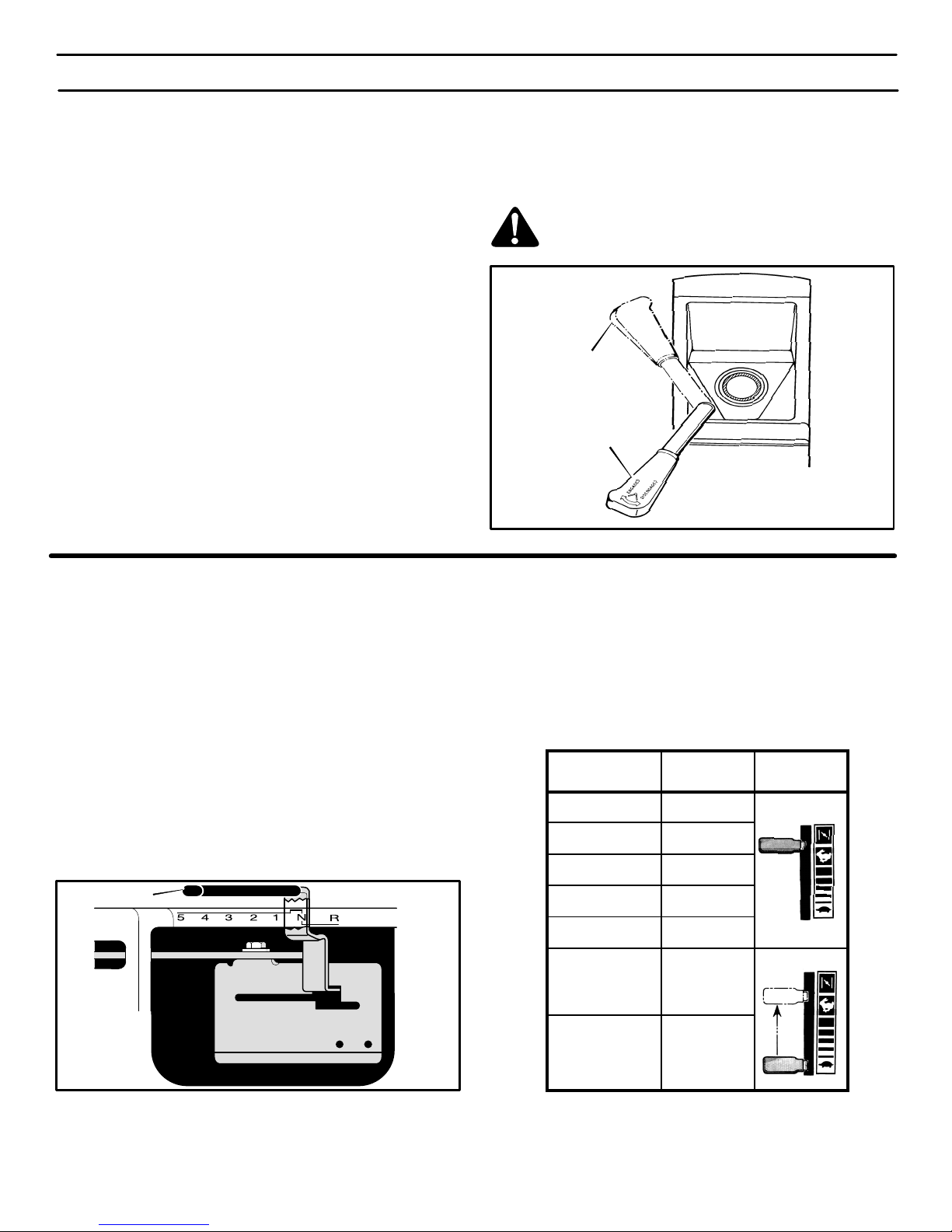
HOW TO USE THE SHIFT LEVER
To change the forward speed or the direction of the unit, follow the
steps below.
CAUTION: Before you move the shift lever, completely push
the clutch/brake pedal forward to stop the unit. If the unit is not
stopped, the gearbox can be damaged.
1. Completely push the clutch/brake pedal forward to stop the
unit. Keep your foot on the pedal.
2. Move the throttle control lever to the SLOW position.
3. To move the shift lever to neutral (N) from a forward gear, pull
the shift lever back and then move to the right (Figure 8).
4. To move the shift lever to a forward gear from neutral (N), pull
the shift lever to the left and then push the shift lever forward.
5. SLOWLY release the clutch/brake pedal. Do not keep your foot
on the pedal.
Shift Lever
Figure 8
6. Move the throttle control to the FAST position.
7. To move the shift lever to reverse, stop the unit. Move the shift
lever back to reverse (R).
NOTE: Belt noise can occur when the clutch is engaged. This
noise is normal and does not affect the operation of the unit.
FUNCTION
SHIFT LEVER
THROTTLE
5 Speeds
Trimming
1
FAST
Bagging Grass 1 or 2
Mulching Grass 1 or 2
Normal Mowing 2 or 3
Easy Mowing 3 or 4
FAST
SLOW
THROTTLE
SLOW – FAST
Transport 5
Pull Behind
2 or 3
Attachments
THROTTLE
F–000614J
12
OPERATION
HOW TO SET THE PARKING BRAKE
1. Completely push the clutch/brake pedal forward.
2. Lift the parking brake lever (Figure 9).
3. Remove your foot from the clutch/brake pedal and then release
the parking brake lever. Make sure the parking brake will hold
the unit.
4. T o release the parking brake, completely push the clutch/brake
pedal forward. The parking brake will automatically release.
WARNING: Before you leave the operator’s position,
move the shift lever to the neutral (N) position. Set the
parking brake. Move the attachment clutch to the
DISENGAGE position. Stop the engine and remove
the ignition key .
HOW TO CHANGE THE CUTTING HEIGHT
To change the cutting height, raise or lower the lift lever as follows.
1. Move the lift lever down to lower the mower housing and up to
raise the mower housing.
2. When you ride on a sidewalk or road, move the lift lever to the
highest position and move the attachment clutch to the DISENGAGE position.
Lift Lever
Parking Brake
Lever
Figure 9
HOW TO STOP THE UNIT
1. Completely push the clutch/brake pedal forward to stop the
unit. Keep your foot on the pedal.
2. Move the attachment clutch to the DISENGAGE position.
3. Move the shift lever to the NEUTRAL position.
4. Set the parking brake.
HOW TO TRANSPORT THE UNIT
To transport the unit, follow the steps below.
1. Move the attachment clutch to the DISENGAGE position
2. Raise the lift lever to the highest position.
WARNING: Make sure the parking brake will hold the
unit.
5. Move the throttle control to the SLOW position.
6. To stop the engine, turn the ignition key to the OFF position. Remove the key.
3. Move the throttle control to a position between SLOW and
FAST.
4. To go faster, move the shift lever to a faster speed.
F–000614J
13

OPERATION
HOW TO OPERATE WITH THE MOWER HOUSING
WARNING: The deflector is a safety device. Do not remove the deflector. The deflector forces the discharged material toward the ground. Always keep the
deflector in the down position. If the deflector is damaged, replace the deflector with an original equipment
part from an authorized service center.
1. Start the engine.
2. Move the lift lever to a height of cut position.
IMPORTANT: In high or thick grass, cut the grass in the
highest position first and then lower the mower housing to
a lower position.
3. Move the throttle control to the SLOW position.
4. Move the attachment clutch to the ENGAGE position.
5. Push the clutch/brake pedal completely forward.
6. Move the shift lever to one of the speed settings.
NOTE: When you mow in heavy grass or mow with a
bagger, put the shift lever in the slowest speed.
7. Slowly release the clutch/brake pedal.
8. Move the throttle control to the F AST position. If you need to go
faster or slower, stop the unit and move the shift lever to another
speed setting.
9. Make sure the level of cut is still correct. After you mow a short
distance, look at the area that was cut. If the mower housing
does not cut level, see the instructions on “How To Level The
Mower Housing” in the Service And Adjustment section.
WARNING: For better control of the unit, always
select a safe speed.
HOW TO OPERATE THE UNIT ON HILLS
WARNING: Do not ride up or down slopes that are too
steep to back straight up. Never ride the unit across
a slope. See the “Slope Guide” in the back of this
book for information on how to check slopes.
1. Before you ride up or down a hill, move the shift lever to the
slowest speed.
2. Do not stop or change speed settings on a hill. If you must stop,
quickly push the clutch/brake pedal forward and set the parking
brake.
3. To start again, make sure the shift lever is in the slowest speed.
Move the throttle control to the SLOW position. Slowly release
the pedal.
4. If you must stop or start on a hill, always have enough space
for the unit to roll when you release the brake and engage the
clutch.
5. Be very careful when you change directions on a hill. When on
a slope or in a turn on a hill, move the throttle control to the
SLOW position to help prevent an accident.
F–000614J
14
OPERATION
BEFORE STARTING THE ENGINE
CHECK THE OIL
NOTE: The engine was shipped from the factory filled with SAE
30 weight oil. Check the level of the oil. Add oil as needed.
1. Make sure the unit is level.
NOTE: Do not check the level of the oil while the engine
runs.
2. Clean the area around the dipstick. Remove the dipstick. Wipe
the oil from the dipstick.
3. Insert the dipstick into the oil fill tube. Turn the dipstick clockwise until it is tight. Remove the dipstick. Check the oil level on
the dipstick. The oil level must reach the FULL mark on the
dipstick.
4. If necessary, add oil until the oil reaches the FULL mark on the
dipstick. The quantity of oil needed from ADD to FULL is shown
on the dipstick. Do not add too much oil.
ADD GASOLINE
WARNING: Always use a safety gasoline container.
Do not smoke when adding gasoline to the fuel tank.
Do not add gasoline when you are inside an enclosure. Before you add gasoline, stop the engine and
let the engine cool for several minutes.
Fill the fuel tank with regular
unleaded gasoline. Do not use
premium unleaded gasoline.
Make sure the gasoline is fresh
and clean. Leaded gasoline will
increase deposits and shorten
the life of the valves.
Full
Fuel Tank
CAUTION: A mixture of alcohol (ethanol or methanol) and
gasoline (called gasohol), will attract moisture and cause acid
deposits during storage. While the unit is in storage, the acids
in the fuel can damage the fuel system.
To prevent engine problems with the fuel system, empty the fuel
system before storage of 30 days or longer as follows.
1. Drain the fuel tank.
2. Start the engine. Let the engine run until the fuel lines and the
carburetor are empty .
3. After storage, make sure you use fresh fuel. See the storage
instructions for additional information.
4. Never use engine cleaner or carburetor cleaner in the fuel tank
or permanent damage can occur.
CARBURETOR
The factory settings for the carburetor are for most conditions. If the
engine is operated under the following conditions, you can adjust
the carburetor mixture. See “How To Adjust The Carburetor” in the
Service And Adjustment section.
1. The engine has a loss of power or does not run smooth.
2. A change from summer to winter operation.
3. A 40 degree change in the operation temperature. The carburetor was adjusted at 80 degrees at the factory.
4. The engine is operated above 4,000 feet.
HOW TO START THE ENGINE
WARNING: The electrical system has an operator
presence system that includes a sensor switch
mounted in the seat. These components tell the electrical system if the operator is sitting on the seat. This
system will stop the engine when the operator leaves
the seat if the attachment clutch is engaged. For your
protection, always make sure this system operates
correctly.
NOTE: The engine will not start unless you depress the
clutch/brake pedal, move the shift lever to the neutral (N)
position, and move the attachment clutch to the DISENGAGE
position.
1. Sit in the middle of the seat. Push the clutch/brake pedal completely forward. Keep your foot on the pedal.
2. Move the shift lever to the neutral (N) position.
HOW TO START WITH A WEAK BATTERY
If the battery is too weak to start the engine, the battery needs to be
charged. If “Jumper Cables” are used to start the engine in an
emergency, follow the procedure below.
NOTE: The unit is equipped with a 12 volt negative to ground
system. Also, the other vehicle must have a 12 volt negative to
ground system.
WARNING: Do not smoke. The fumes from the battery
acid can cause an explosion. Keep the battery away
from any flames or sparks. To prevent sparks, fasten
the red “Jumper cable” to the positive (+) terminal before connecting the black “Jumper cable”.
F–000614J
3. Make sure the attachment clutch is in the DISENGAGE position.
4. Move the throttle control completely forward to the CHOKE or
FAST position. Some models have a separate choke knob. Pull
the choke knob to the full CHOKE position.
5. Turn the ignition key to the START position. Release the key
when the engine starts.
NOTE: If the engine does not start after four or five tries,
move the throttle control to the F AST position. Again try to
start the engine. If the engine will not start, see the
TROUBLE SHOOTING CHART.
6. Slowly move the throttle control to the SLOW position. If model
has a separate choke knob, push in the choke knob.
7. Let a cold engine run for several minutes. Begin work when the
engine is warm. To start a hot engine, move the throttle control
to a position between FAST and SLOW.
NOTE: If the seat is raised when starting the engine, move the
attachment clutch to the DISENGAGED position and engage
the parking brake.
1. Connect each end of the RED “Jumper Cable” to the positive
(+) terminals of each battery. Make sure you do not touch the
chassis with the cables.
2. Connect one end of the BLACK “Jumper Cable” to the negative
(–) terminal of the charged battery .
3. Connect the other end of the BLACK “Jumper Cable” to the
mower’s engine block.
4. Start the engine that has the weak battery last. Allow the engine
to run.
5. To disconnect the “Jumper Cables”, reverse the above steps.
15
OPERATION
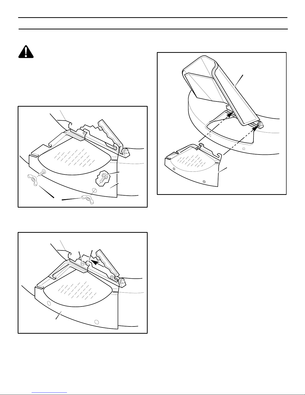
HOW TO CHANGE THE MULCHER PLATE
WARNING: To prevent the engine from starting, disconnect the wire from the spark plug. Make sure the
attachment clutch is in the DISENGAGE position.
The mulcher plate lets you mulch the grass for a clean, fine cut. To
discharge the grass out the side or into a grass bagger, remove the
mulcher plate as follows.
How To Remove The Mulcher Plate
1. Raise the deflector. Remove the two wingnuts B and two car-
riage bolts A (Figure 10).
A
3. Lift the mulcher plate away from the mower housing
(Figure 12).
Deflector
Mulcher Plate
Mulcher Plate
B
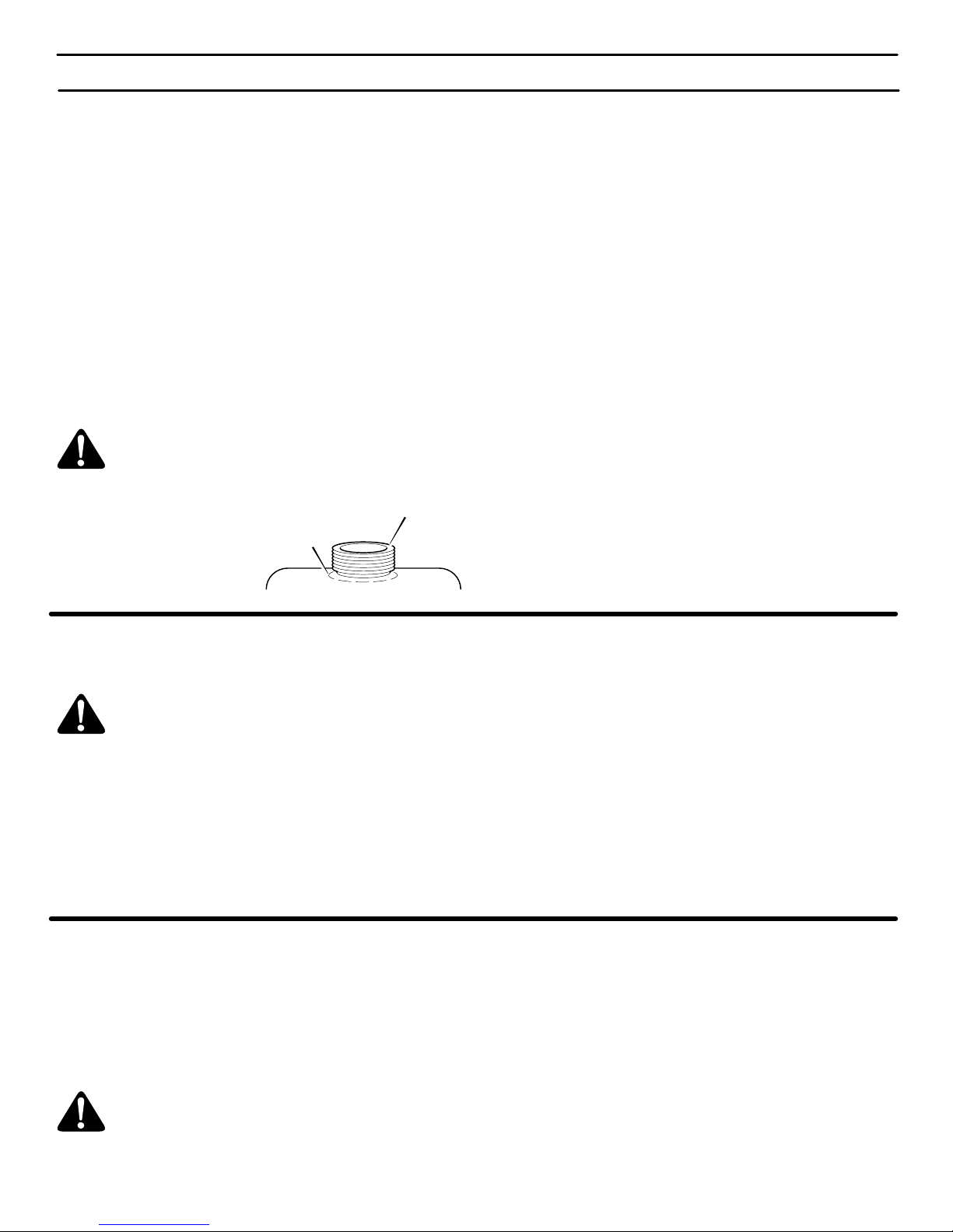
2. Slide the mulcher plate toward the front (Figure 11). Make
sure the tabs on the mulcher plate are not locked behind the
nuts.
To remove, slide forward
T o install, slide backward
Tab
Nut
Mulcher Plate
Figure 10
Figure 11
Figure 12
4. Attach wingnuts B and carriage bolts A to the mulcher plate
for future use.
IMPORTANT: There are several different types of grass. Some
types of grass are more difficult to cut. If you remove the
mulcher plate and the grass does not discharge correctly,
replace the blade with a standard blade. The part number of the
standard blade is 56212E701.
How To Install The Mulcher Plate
1. Remove wingnuts B and carriage bolts A from the mulcher
plate.
2. Raise the deflector. Slide the mulcher plate under the deflec-
tor (Figure 12).
3. Push the mulcher plate to the rear . (Figure 11). Make sure the
two tabs on the mulcher plate are locked around the two nuts
for the deflector bracket.
4. Fasten the mulcher plate with two wingnuts B and two carriage bolts A (Figure 10).
F–000614J
16
OPERATING TIPS
OPERATION
1. Check the attachment clutch for correct adjustment. For the
blade(s) to disengage correctly, the adjustment must be correct.
2. Before you use the unit, check the oil in the engine and add oil
if necessary.
3. If the engine will not start, first make sure the wire is attached
to the spark plug.
4. Make sure all the belts are inside all the belt guides. See the instructions on how to remove and install the motion drive and
mower drive belts.
MOWING AND BAGGING TIPS
1. For a lawn to look better, check the cutting level of the mower
housing. See “How To Level The Mower Housing” in the Service And Adjustment section.
2. For the mower housing to cut level, make sure the tires have
the correct amount of air pressure (PSI).
3. Every time you use the unit, check the blade. If the blade is bent
or damaged, immediately replace the blade. Also, make sure
the nut for the blade is tight.
4. Keep the blade(s) sharpened. A worn blade(s) will cause the
ends of the grass to turn brown.
5. Do not cut or bag grass that is wet. W et grass will not discharge
correctly. Let the grass dry before cutting.
6. Use the left side of the mower housing to trim near an object.
7. Discharge the cut grass onto the mowed area. The result is a
more even discharge of cut grass.
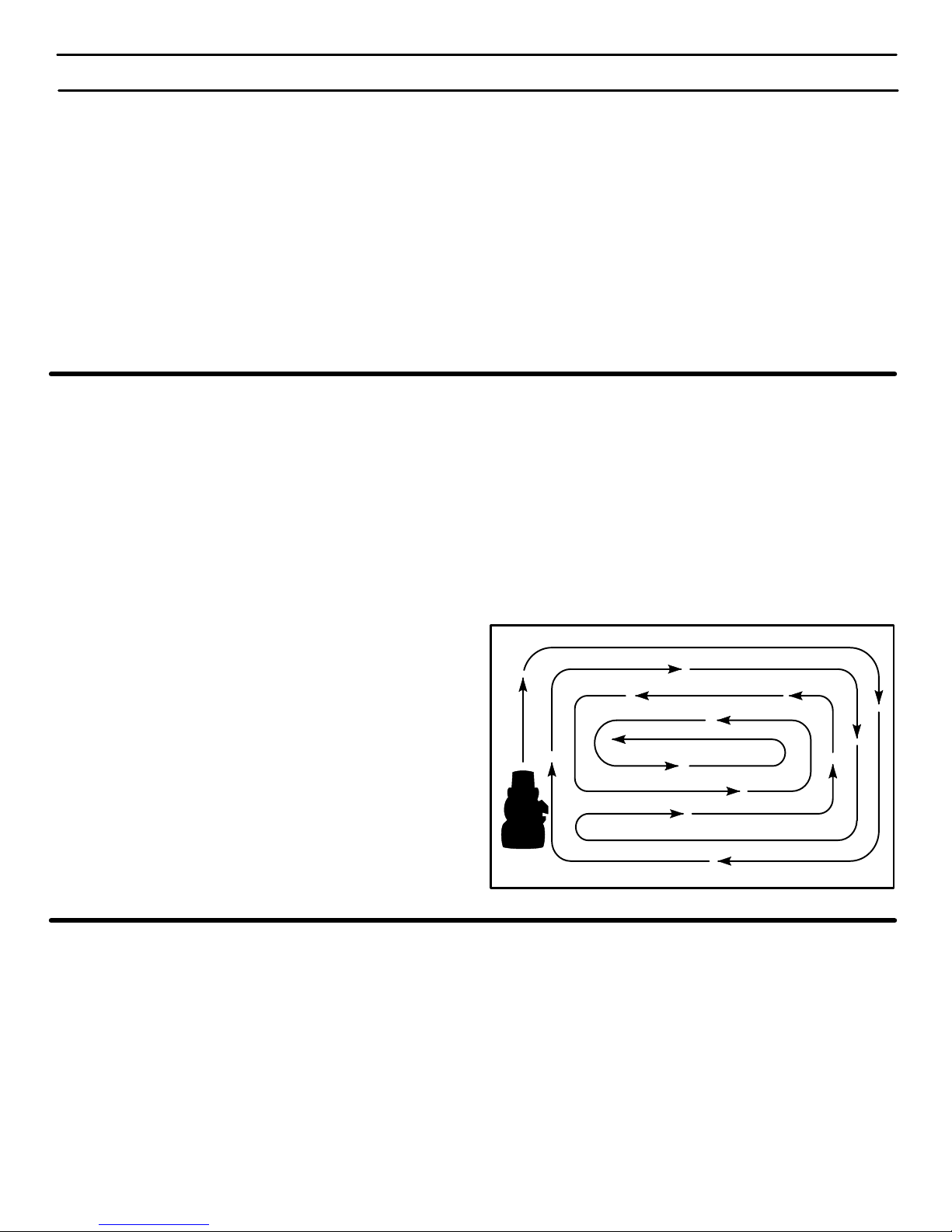
8. When you mow large areas, start by turning to the right so that
the cut grass will discharge away from shrubs, fences, driveways, etc. After one or two rounds, mow in the opposite direction making left turns until finished (Figure 13).
9. If the grass is very high, cut two times to decrease the load on
the engine. First cut with the mower housing in the highest position and then lower the mower housing for the second cut.
10. For better engine performance and an even discharge of the
cut grass, always operate the engine with the throttle in FAST
position.
5. Before you make an inspection, adjustment (except for the carburetor) or repair, make sure the wire from the spark plug is disconnected.
6. Make sure the seat switch wire is connected. If the wire is not
connected, the engine will not start.
7. For longer life of the battery, charge the battery every three
months.
8. Use the shift lever to change the ground speed, not the throttle
control.
9. Belt noise can occur when the blade or clutch is engaged. This
noise is normal and does not affect the operation of the unit.
10. To move forward, always release the clutch/brake pedal slowly.
11. When you use a bagger, operate the engine with the throttle in
FAST position and the shift lever in first or second gear.
12. For better cutting performance and a quality cut, mow with the
shift lever in one of the slower speeds.
13. After each use, clean the bottom and top of the mower housing
for better performance. Also, a clean mower housing will help
prevent a fire.
Figure 13
MULCHING TIPS
When you use a mulcher attachment, the grass is cut into very small
pieces. These small pieces will quickly break down. Because the
nutrients are returned to the soil, the lawn will need less fertilizer. Too
correctly mulch the grass, follow the steps below.
1. Set the throttle in the FAST position. Operate the mower at a
slower ground speed. If ground speed is too fast, the grass will
not have an even cut.
2. Keep a sharp edge on the blade. A blade that is not sharp will
cause the ends of the grass to become brown.
3. Make sure the grass is dry. Wet grass is difficult to cut.
F–000614J
4. Set the height of the mower housing so that only the top third
of the grass is cut. If the grass is too high, set the height of the
mower housing to the maximum height. Then, lower the mower
housing for the second cut. Also, instead of using the full width
of the mower housing, mulch at half the width.
5. Clean the bottom of the mower housing. Grass and other debris
can keep the mower from working correctly.
6. If the grass grows fast, mulch more often.
7. If an area needs improvement, mulch a second time.
17

M
E
N
G
G
CUSTOMER RESPONSIBILITIES
MAINTENANCE CHART
PROCEDURE
Blade, Inspect and Sharpen
Attachment Clutch, Check
Brake, Check
M
O
Clutch, Check
W
Tires, Check
R
Battery, Check and Charge
Battery, Clean
Lubrication
Oil, Check
Cooling System, Clean
E
Oil, Change
Air Filter, Clean
I
Muffler, Check
N
Spark Plug, Check
E
Fuel Filter, Replace (Remote Fuel Tanks Only)
Spark Plug, Replace
EACH
USE
√
√
FIRST
2
HOURS
EVERY
25
HOURS
EVERY
50
HOURS
EVERY
100
HOURS
√
√
√
√
√ √
√ √
√ √
√ √
√ √ √
√ √
√
√ √
√
√
BEFORE
STORAGE
GENERAL RECOMMENDATIONS
1. The owner’s responsibility is to maintain this product. This will
extend the life of the product and is also necessary to maintain
warranty coverage.
2. Check the spark plug, drive brake, lubricate the unit, and clean
the air filter once a year.
3. Check the fasteners. Make sure all fasteners are tight.
CHECK THE TIRES
Check the air pressure in the tires. Tires with too much air pressure
will cause the unit to ride rough. Also, the wrong air pressure will
keep the mower housing from cutting level. The correct air pressure
(PSI) is as follows. Semi–pneumatic front tires do not require air.
Front Tires 22 PSI (1.5 BAR)
Rear Tires 14 PSI (1 BAR)
F–000614J
4. Follow the Customer Responsibility and the Service And Adjustment section to keep the unit in good operating condition.
WARNING: Before you make an inspection, adjustment, or repair to the unit, disconnect the wire to the
spark plug. Remove the wire from the spark plug to
prevent the engine from starting by accident.
18
 Loading...