

Sears 507.459820,507.459830,SPYDER,SCREAMER,SPYDER 500,CONVERTA-BIKE Owner's Manual

Sears
owners manual
..
--"
MODEl NO.
507.459820
507.459830
CAUTION:
Read Rules for
Safe Operation
and Instructions
Carefully
/
SPYDER
.Assembly
. Operating
. Maintenance
. Repair Parts
-t
o
-t
m
I
n
-<
n
r-
m
SCREAMER
SPYDER
500
---~~ ~~
.
-
l[
f\
-
-S5~~~
~@~~~~ ~~; (£0)0--
. .
I'
II @}{]O:[;&@@, mlJl.
@
0;0
."
11 ~. :1
Printed in U.S.A.
J
TOTE-CYCLE ASSEMBLY
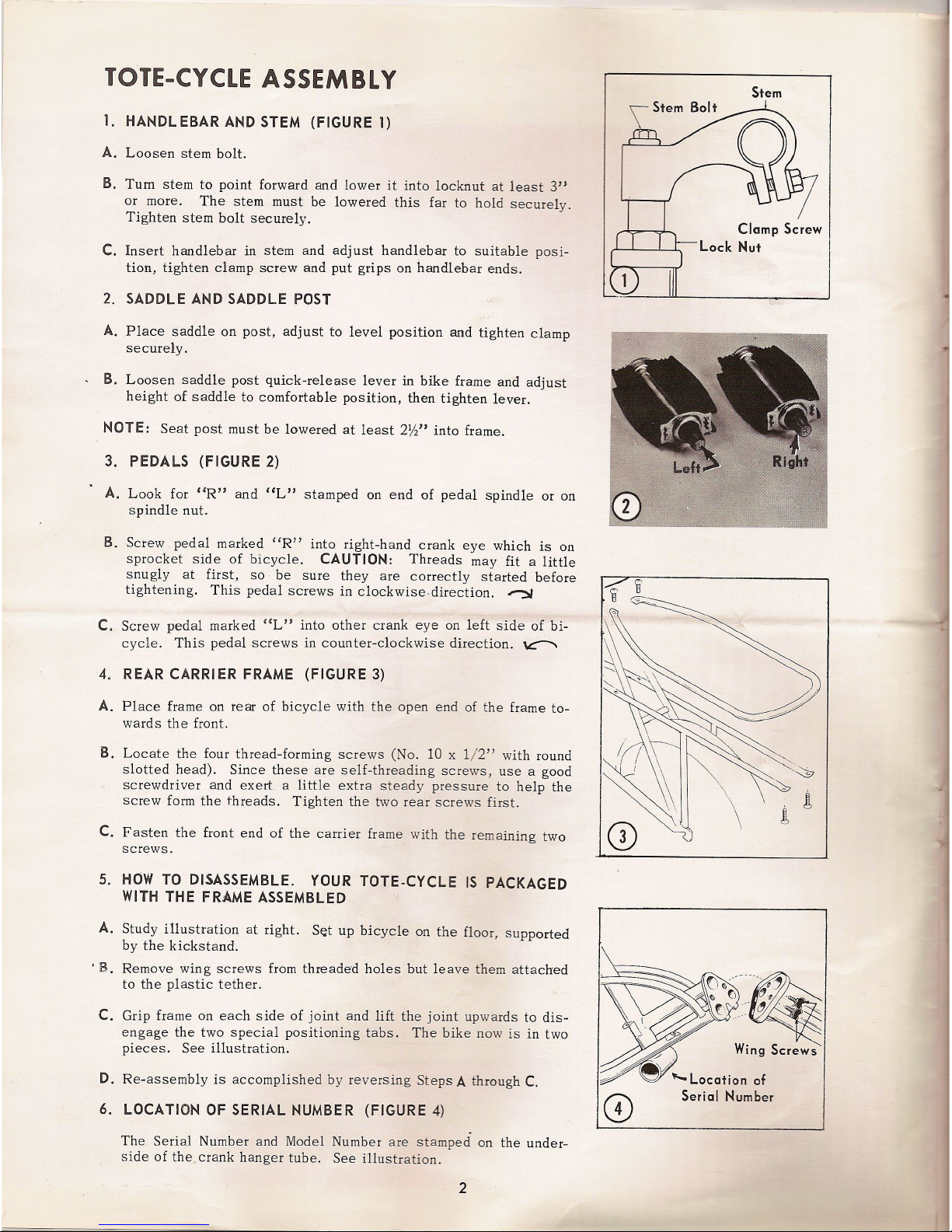
1. HANDL EBAR AND STEM (FIGURE 1)
A. Loosen stem bolt.
B.
Turn
stem to point forward and lower it into locknut at least 3"
or more. The stem must be lowered this far to hold securely.
Tighten stem bolt securely.
C. Insert handlebar in stem and adjust handlebar to suitable posi-
tion, tighten clamp screw and put grips on handlebar ends.
2. SADDLE AND SADDLE POST
A. Place saddle on post, adjust to level position and tighten clamp
securely.
-
B. Loosen saddle post quick-release lever in bike frame and adjust
height of saddle to comfortable position, then tighten lever.
NOTE: Seat post must be lowered at least
2W'
into frame.
3. PEDALS (FIGURE 2)
.
A. Look for «R" and "L" stamped on end of pedal spindle or on
spindle nut.
B. Screw pedal marked
"R" into right-hand crank eye which is on
sprocket side of bicycle. CAUTION: Threads may fit a little
snugly at first, so be sure they are correctly started before
tightening. This pedal screws in clockwise. direction.
"':S
C. Screw pedal
marked
C(L"
into other crank eye on left side of bi-
cycle. This pedal screws in counter-clockwise direction.
~
4.
REAR CARRI ER FRAME (FIGURE 3)
A. Place frame on rear of bicycle with the open end of the frame to-
wards the front.
B.
Locate the four thread-forming screws (No. 10 x 1/2" with round
slotted head). Since these are self-threading screws, use a good
screwdriver and exert. a
little extra steady pressure to help the
screw form the threads. Tighten the two rear screws first.
C. Fasten the front end of the carrier frame with the remaining two
screws.
5. HOW TO DISASSEMBLE.
YOUR
TOTE.CYCLE IS PACKAGED
WITH THE FRAME ASSEMBLED
A.
Study illustration
at right. S~t up bicycle on the floor, supported
by the kickstand.
.
B.Remove
wing
screws from threaded holes but leave them attached
to the plastic tether.
C. Grip frame on each side of joint and lift the joint upwards to dis-
engage the two special positioning tabs. The bike now is in two
pieces.
See
illustration.
D. Re-assembly is accomplished by reversing Steps A throughC.
6. LOCATION OF SERIAL NUMBER (FIGURE 4)
The Serial Number and Model Number are stamped on the under-
side of the,
crank
hanger tube. See illustration.
2
Stem
Clamp Screw
I
Lock Nut
I
CD
7. TIRES
Never ride on under-inflated tires. Tires should be
kept inflated to the pressure marked on the tire.
CALI
PER BRAKE ADJUSTMENT
Make
sure the brake releases evenly on each side. If not, tap the
return spring on the side which releases too far.
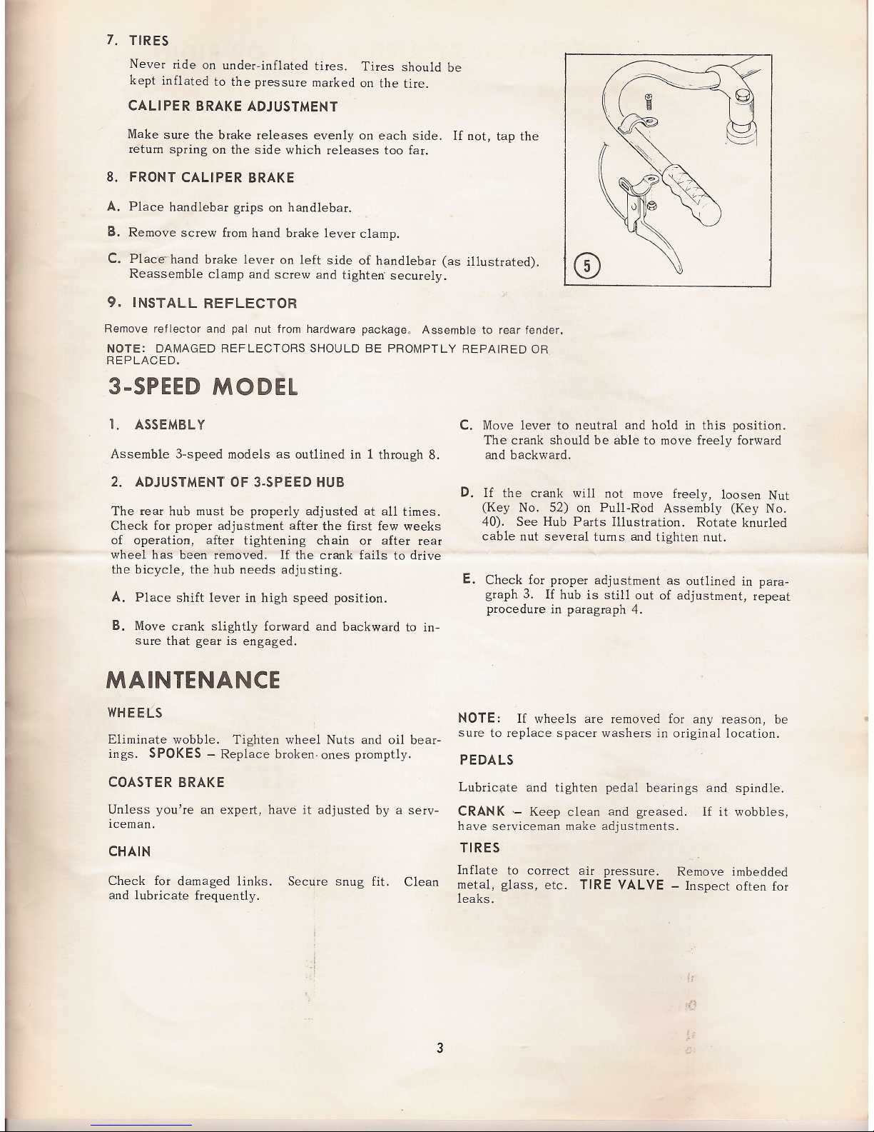
8.
FRONT CALIPER BRAKE
A. Place handlebar grips on handlebar.
S. Remove screw from hand brake lever clamp.
C. Place" hand brake lever on left side of handlebar (as illustrated).
Reassemble clamp and screw and tighten: securely.
9. INSTALL REFLECTOR
Remove reflector and pal nut from hardware packageo Assemble to rear fender.
NOTE: DAMAGED REFLECTORS SHOULD BE PROMPTLY REPAIRED OR
REPLACED.
3-SPEED MODEL
1.
ASSEMBL
Y
Assemble 3-speed models as outlined in 1 through
8.
2. ADJUSTMENT OF 3.SPEED
HUB
The rear hub must be properly adjusted at all times.
Check for proper adjustment after the first few weeks
of operation, after tightening chain or after rear
wheel has been removed. If the crank fails to drive
the bicycle, the hub needs adjusting.
A. Place shift lever in high speed position.
B. Move crank slightly forward and backward to in-
sure that gear is engaged.
MAINTENANCE
WHEELS
Eliminate wobble. Tighten wheel Nuts and oil bear-
ings.
SPOKES
- Replace broken. ones promptly.
COASTER
BRAKE
Unless you're an expert, have it adjusted by a serv-
Iceman.
CHAIN
Check for damaged links.
and lubricate frequently.
Secure snug fit.
Clean
,
i
.,
C. Move lever to neutral and hold in this position.
The crank should be able to move freely forward
and backward.
D. If the crank will not move freely, loosen Nut
(Key No. 52) on Pull-Rod Assembly (Key No.
40). See Hub Parts Illustration. Rotate knurled
cable nut several turns and tighten nut.
E. Check for proper adjustment as outlined in para-
graph 3. If hub is still out of adjustment, repeat
procedure in paragraph 4.
NOTE:
If wheels are removed for any reason, be
sure to replace spacer washers in original location.
PEDALS
Lubricate and tighten pedal bearings and spindle.
CRAN K
'-
Keep clean and greased.
have serviceman make adjustments.
If it wobbles,
TIRES
Inflate to correct air pressure. Remove imbedded
metal, glass, etc. TIRE
VALVE -
Inspect often for
leaks.
I.
3
-
 Loading...