

Page 1

Owner's Manual
®
STOP
DO NOT RETURN TO STORE
For Missing Parts or Assembly
Questions Call 1-866-576-8388
15 GALLON 35 PSI SPRAYER
Model No. 486.245313
CAUTION:
Before using this product, read
this manual and follow all Safety
Rules and Operating Instructions.
Sears, Roebuck and Co., Hoffman Estates, IL 60179 U.S.A.
www.sears.com/craftsman
PRINTED IN U.S.A. FORM NO. 41054 (03/07/08)
• Safety
• Assembly
• Operation
• Maintenance
• Parts
Page 2

TABLE OF CONTENTS
SAFETY RULES .............................................................. 2
FULL SIZE HARDWARE CHART .................................... 3
CARTON CONTENTS ..................................................... 4
ASSEMBLY ...................................................................... 4
OPERATION .................................................................... 7
MAINTENANCE .............................................................. 8
STORAGE ....................................................................... 8
SPRAYING CHARTS ....................................................... 9
REPAIR PARTS ILLUSTRATION .................................. 10
REPAIR PARTS LIST..................................................... 11
PARTS ORDERING/SERVICE ......................... Back Page
WARRANTY
ONE YEAR FULL WARRANTY
When operated and maintained according to the instructions supplied with it, if this Sprayer fails due to a defect in
material or workmanship within one year from the date of purchase, call 1-800-4-MY-HOME® to arrange for free repair (or
replacement if repair proves impossible).
If this product is used for commercial or rental purposes, this warranty applies for only 90 days from the date of purchase.
This warranty gives you specic legal rights, and you may also have other rights which vary from state to state.
Sears, Roebuck and Co., D817WA, Hoffman Estates, IL 60179
The model number and serial numbers will be found on
a decal attached to the sprayer.
You should record both the serial number and the date of
purchase and keep in a safe place for future reference.
MODEL NUMBER: 486.245313
SERIAL NUMBER: __________________
DATE OF PURCHASE: __________________
SAFETY
Any power equipment can cause injury if operated improperly or if the user does not understand how to operate the equipment.
Exercise caution at all times when using power equipment.
• Read this owners manual carefully before attempting
to assemble or operate this sprayer.
• Read your vehicle owners manual for operating and
safety rules before using this equipment.
• Never allow children to operate this sprayer, and do
not allow adults to operate without proper instructions.
• Do not allow anyone to ride on or sit on this sprayer.
• Do not allow passengers on the towing vehicle.
• Keep the area of operation clear of all persons,
particularly small children. Also keep area clear of
pets.
• Read the chemical label carefully for instructions and
caution notes on handling and mixing of chemicals.
• Wear eye and hand protection and wear protective
clothing when handling and applying lawn chemicals.
• Do not spray on windy days.
• Attachment of this sprayer may affect your tractor's
braking and stability. Be aware of your tractor's
capabilities. Refer to the safety rules in the vehicle
owner's manual concerning safe operation on slopes.
Be aware of changing conditions on slopes. STAY
OFF OF STEEP SLOPES.
• Operate at reduced speed on rough terrain, along
ditches and on hillsides to prevent loss of control.
• Follow maintenance and lubrication instructions as
outlined in this manual.
Look for this symbol to point out important safety precautions. It means — Attention!! Become
alert!! Your safety is involved.
2
Page 3
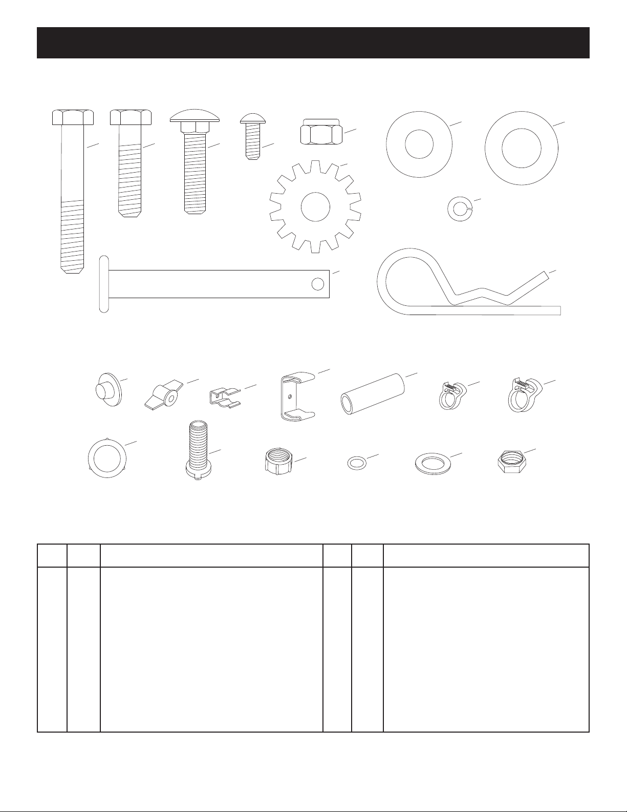
HARDWARE PACKAGE CONTENTS
A
G
I
N
O
J
K
B
C
D
F
E
NOT SHOWN FULL SIZE
R
P
S
T
U
Q
V
H
L
M
W
X
SHOWN FULL SIZE
KEY QTY. DESCRIPTION
A 8 Hex Bolt, 5/16" x 2"
B 2 Hex Bolt, 5/16" x 1-1/4"
C 2 Carriage Bolt, 5/16" x 1-1/4"
D 2 Screw, #10 x 1/2"
E 10 Nylock Nut, 5/16"
F 2 Flat Washer, 5/16"
G 4 Flat Washer, 1/2"
H 2 Lock Washer, #10
I 2 Washer, 5/16" Tooth Lock
J 1 Hitch Pin
K 1 Hair Cotter Pin
L 2 Palnut
KEY QTY. DESCRIPTION
M 2 Knob
N 1 Spray Gun Clip, Small
O 1 Spray Gun Clip, Large
P 2 Spacer
Q 1 Coiled Hose Clamp
R 2 Hose Clamp, 3/8"
S 1 Gasket, 3/4" Garden Hose
T 1 Drain Body
U 1 Nylon Cap
V 1 O-Ring
W 1 Nylon Washer, 11/16"
X 1 Nylon Nut
3
Page 4
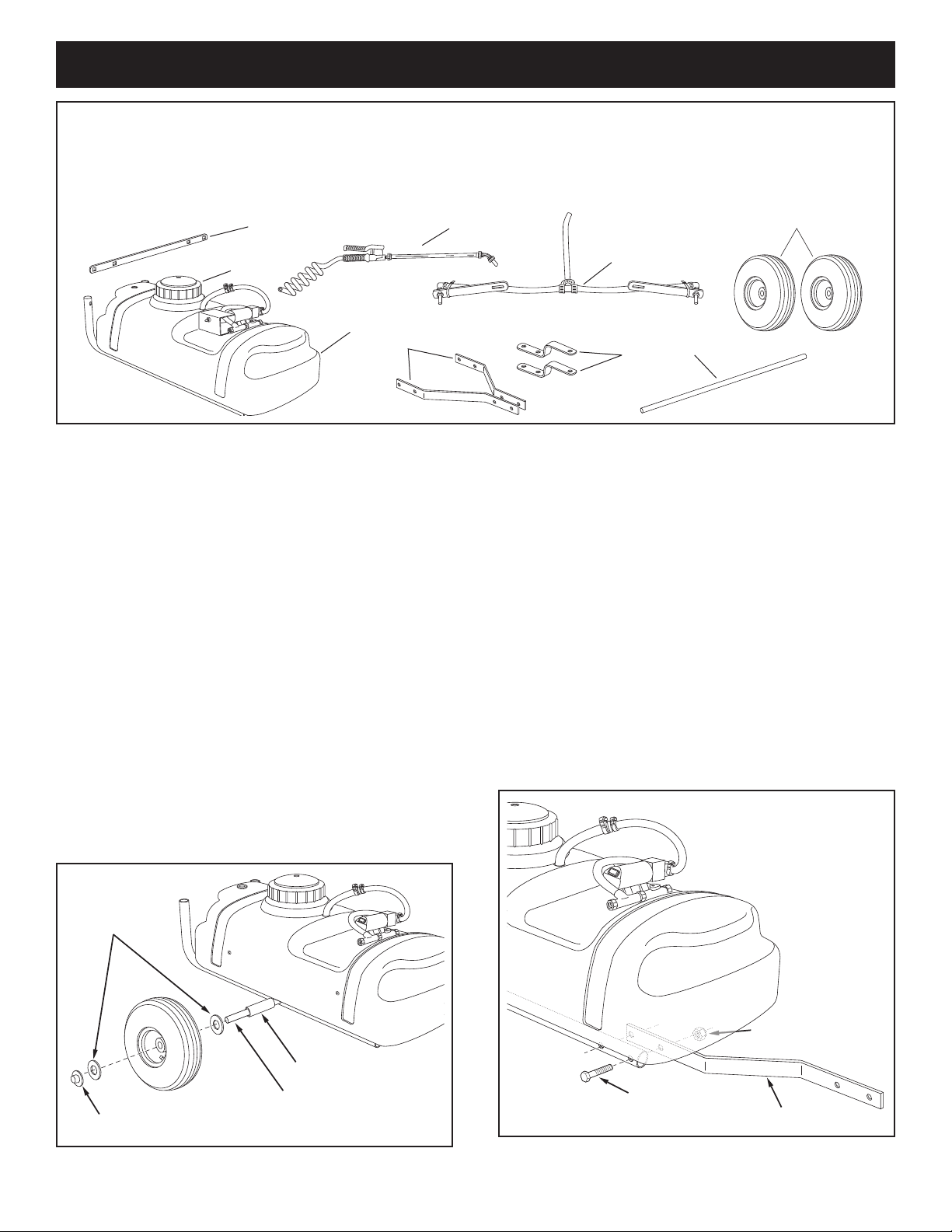
CARTON CONTENTS
2
1
5
8
7
3
4
9
6
1/2" FLAT
WASHER
SPACER
AXLE
PALNUT
5/16" x 2"
HEX BOLT
5/16" NYLOCK NUT
HITCH ARM
ASSEMBLY
1. Boom Mount Bracket
2. Lid
3. Tank with Frame Tubes
4. Spray Gun Assembly
5. Boom Assembly
6. Hitch Arms (2)
REMOVAL OF PARTS FROM CARTON
• Remove all parts and hardware packages from the
carton. Lay out all parts and hardware and identify
using the illustrations on pages 3 and 4.
TOOLS REQUIRED FOR ASSEMBLY
(2) 1/2" Wrenches
(1) Screwdriver
(1) Pliers
(1) Hammer
7. Hitch Brackets (2)
8. Axle
9. Wheels (2)
• Assemble the axle through the holes in the frame
tubes. You may need to slightly loosen the bolts in the
frame tubes to make the axle t. Retighten the bolts
only enough to atten the lockwashers. See gure 1.
• Assemble a spacer, a 1/2" at washer, a wheel and
another 1/2" at washer onto the axle. Lightly tap a
palnut onto the end of the axle. Repeat on other end
of axle. See gure 1.
FIGURE 1
• Assemble a hitch arm to the inside of a frame tube
underneath the tank. Use two 5/16" x 2" hex bolts and
5/16" nylock nuts as shown in gure 2. Do not tighten
yet. Repeat for other side.
FIGURE 2
4
Page 5
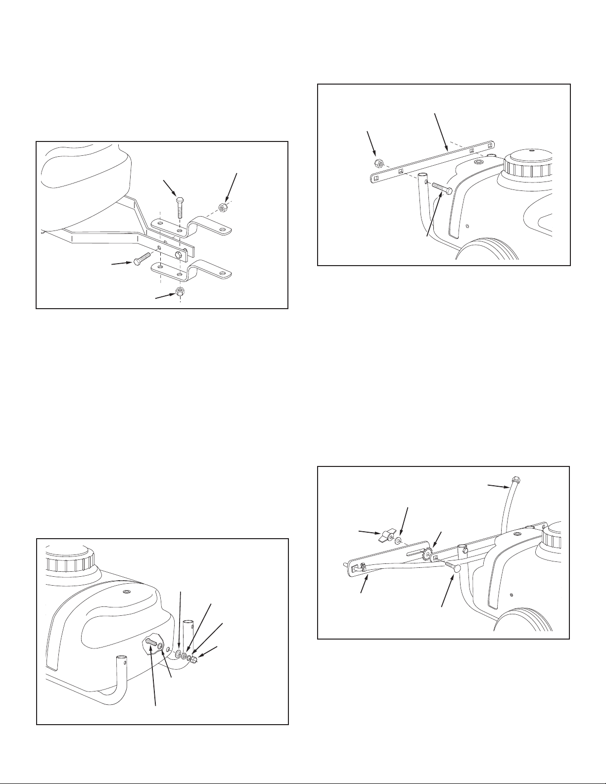
• Fasten the ends of the hitch arms together using two
NYLON CAP
DRAIN BODY
HOSE
GASKET
NYLON
WASHER
NYLON NUT
O-RING
5/16" NYLOCK NUT
BOOM MOUNT
BRACKET
5/16" x 2"
HEX BOLT
5/16" x 2"
HEX BOLT
5/16" NYLOCK NUT
5/16" x 1-1/4"
HEX BOLT
5/16" NYLOCK NUT
CARRIAGE BOLT
5/16" x 1-1/4"
KNOB
5/16" WASHER
WASHER
(TOOTH LOCK)
BOOM BAR
BOOM CONNECTING HOSE
5/16" x 1-1/4" hex bolts and 5/16" nylock nuts. Do not
tighten yet. See gure 3.
• Assemble the hitch brackets to the hitch arms using
two 5/16" x 2" hex bolts and 5/16" nylock nuts.
Position each bolt behind one of the cross bolts in the
hitch arms. Do not tighten yet. See gure 3.
FIGURE 3
• Assemble the boom mount bracket to the rear of the
hitch tubes using two 5/16" x 2" hex bolts and 5/16"
nylock nuts. See gure 5.
FIGURE 5
• At this time tighten all bolts starting with the bolts in
gure 2, then the bolts in gure 3.
• Install the drain in the rear of the tank as shown in
gure 4. Place a 3/4" garden hose gasket onto the
drain body and insert the drain body out through the
hole in rear of the tank. Outside the tank, assemble
the nylon washer and then the nylon nut onto the
drain body. Tighten the nut securely enough to prevent
leaking, being careful not to damage the plastic parts.
Place the O-ring inside the nylon cap and screw the
cap onto the end of the drain body.
• Assemble the boom bars to the boom mount bracket
using two 5/16" x 1-1/4" carriage bolts, tooth lock
washers (between the bar and bracket), 5/16" at
washers and knobs. The boom connecting hose
should extend upward. See gure 6.
NOTE: Make sure the nozzle openings face straight
down when the boom bars are in the horizontal operating
position.
FIGURE 6
FIGURE 4
5
Page 6
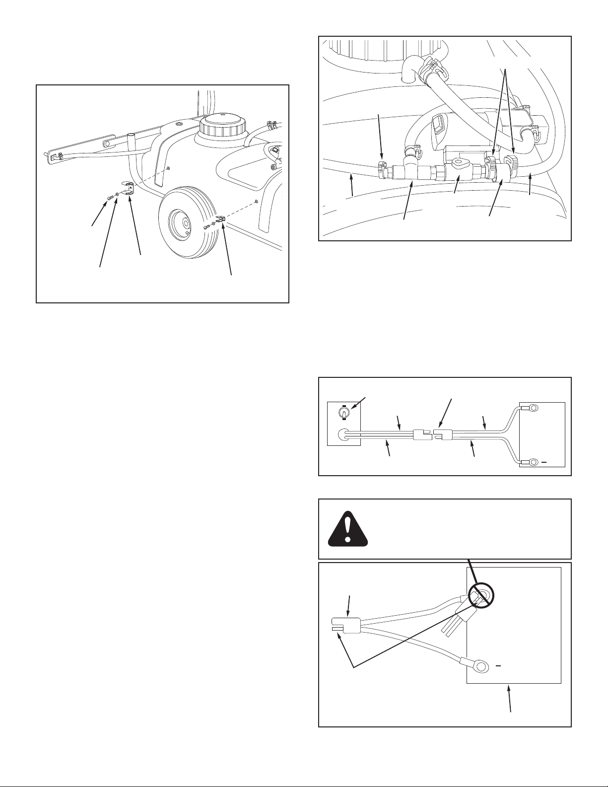
• Assemble the large and small spray gun clips to the
SPRAY GUN
CLIP (LARGE)
SPRAY GUN
CLIP (SMALL)
#10 x 1/2"
SCREW
#10 LOCK
WASHER
COILED HOSE CLAMP
CONDUIT
1/4" TEE
ON - OFF
VALVE
SPRAY GUN
HOSE
BOOM
CONNECTING
HOSE
3/8" HOSE CLAMPS
BROWN
PUMP SWITCH
RED
QUICK COUPLER
BATTERY
+
RED
BROWN
PLUG
NEGATIVE PIN
12 VOLT TRACTOR BATTERY
POSITIVE
"HOT"
POST
+
NEGATIVE
POST
side of the tank using two #10 x 1/2" screws and #10
lock washers. See gure 7.
FIGURE 7
FIGURE 8 VIEWED FROM FRONT
• To connect the wire harness to the tractor, attach the
red wire to the positive post on the battery or to the
"HOT" connection on a tractor switch or ammeter.
The brown wire may be grounded or connected to the
negative battery post. See gures 9 and 10.
• Slide a 3/8" hose clamp onto the boom connecting
hose. Place the end of the hose through the conduit
clamp (attached to the pump) and then slide a second
3/8" hose clamp onto the hose. Leave hose clamps
loose for now. See Figure 8.
• Push the hose onto the hose adapter in the end of
the "On-Off" valve. Tighten the hose clamp around the
hose and adapter. See gure 8.
• Position the valve and hose clamp up against the
conduit clamp. Slide the other hose clamp against the
other side of the conduit clamp. Tighten the clamp
without collapsing the hose. See gure 8.
• Slide the coiled hose clamp onto the spray gun hose
and then push the hose onto the hose adapter on the
1/4" tee tting. Tighten the hose clamp around the
hose and adapter. See gure 8.
• Snap the spray gun into the clips on the front of the
tank. (The large clip holds the spray gun handle and
the small clip holds the wand.) Refer to gure 7.
IMPORTANT: This sprayer should be connected to 12
volt batteries only!
FIGURE 9
DANGER! Never allow negative pin on
plug to come in contact with positive
"hot" post on battery. Fire or explosion
may result!
FIGURE 10
6
Page 7
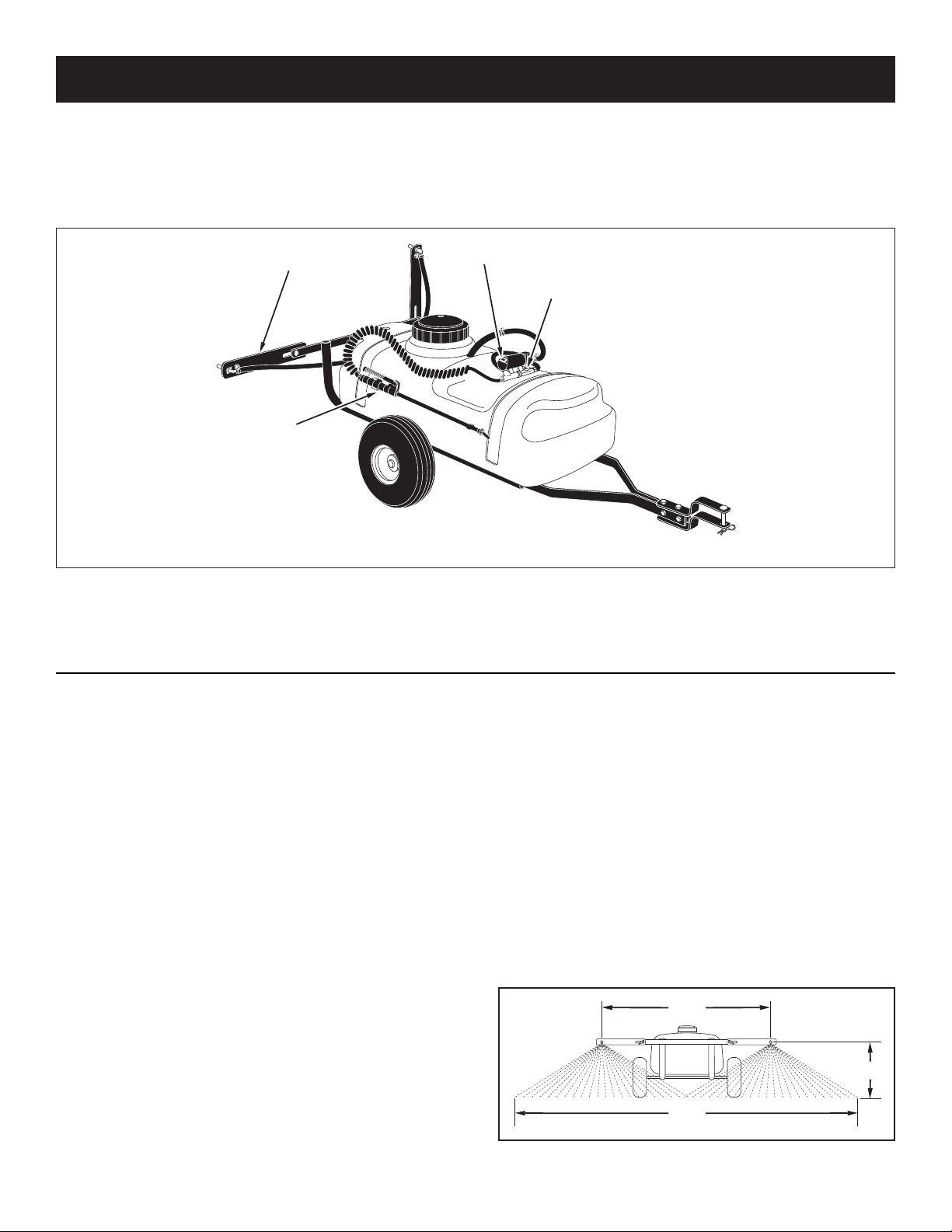
OPERATION
80"
40"
14"
ON-OFF SWITCH
ON-OFF VALVE
SPRAY GUN
BOOM ARM
KNOW YOUR SPRAYER
Read this owner's manual and safety rules before operating your sprayer.
Compare the illustration below with your sprayer to familiarize yourself with the various controls and their locations.
ON-OFF SWITCH Turns pump/motor on or off.
ON-OFF VALVE Turns the ow on or off from the pump
to the boom nozzles.
BOOM ARM Swivels up and down and adjusts in and
BEFORE STARTING
It is important to test the boom and spray gun with
plain water before attempting actual spraying. This will
enable you to check the sprayer for leaks and to set the
spray pattern and nozzle pressure. If a leak should occur,
thread tape may be used to better seal the tting.
PUMP PRESSURE SWITCH
The pump is equipped with a pressure switch. The
pressure switch senses outlet pressure of the pump
and will turn off the electrical power to the pump at a
predetermined high pressure point (35 PSI). If the ow
demand is very low, the pump may reach this high
pressure point and the switch will cause "cycling" (the
pump cycles on and off rapidly). This is not a problem
unless the pump is subject to continuous cycling within
one second intervals for long periods of time.
ON-OFF ADJUSTMENT OF BOOM NOZZLES
The sprayer is equipped with an "On-Off" valve for the
boom which allows the ow to the boom nozzles to be
shut off.
out to obtain proper nozzle positioning.
SPRAY GUN Unhooks from tank for spraying shrubs,
small trees or areas inaccessible to the towed sprayer.
ADJUSTING SPRAY GUN NOZZLE
Turn the nozzle on the spray gun to adjust the spray from
a cone shaped ne mist to a straight stream. Maximum
gun pressure is attained with the ON-OFF valve shut off.
SETTING THE BOOM FOR SPRAYING
The correct positioning of the boom places the nozzles
approximately 40" apart and 14" above the ground. This
gives a spray width of approximately 80" with a slight
center overlap. See gure 11.
a. Slide the boom bars out to the ends of the slots.
b. Swivel the boom bars until the nozzles are
approximately 14" above the ground.
c. Make sure the nozzles are adjusted so that the
openings point straight down.
FIGURE 11
7
Page 8
HOW TO USE YOUR SPRAYER
• Determine the approximate square footage of the
area to be sprayed. Use this amount to estimate
the number of gallons that will be required, based
on product recommendations. This can help avoid
unneeded solution left in the tank.
• Determine the application rate (gallons per 1,000
sq. feet or gallons per acre) based on the chemical
manufacturers recommendations.
• Use the tip chart on page 9 to determine what ground
speed will achieve the recommended application rate.
• To determine the throttle setting for attaining the
desired ground speed, mark off 100, 200 and 300
feet intervals. The speed chart at the bottom of
page 9 indicates the number of seconds it takes to
travel these distances. Set the throttle and, with a
running start, travel the distances in the number of
seconds indicated by the speed chart. Once you have
determined the throttle and gear settings needed,
mark the throttle location so that you can easily
resume the same speed after stopping.
• Add the chemical solution to the tank, following the
product instructions.
• Drive to the starting place for spraying.
• Set the boom in position for spraying.
• Set the throttle at the position determined in the 4th
step. Reach back and ip the pump/motor switch to
the "ON" position to start spraying.
• Stay clear of owers, shrubs and evergreen trees
when spraying weed control solutions to prevent
contact of the solution with these sensitive plants.
ATTENTION!
Do not allow chemicals to sit in pump for extended
times of idleness. Some chemicals will damage the
pump valve if allowed to soak untreated for a length
of time. Always ush the pump with water after each
use. See the instructions for cleaning the tank in the
maintenance section for ushing and disposal of
chemicals.
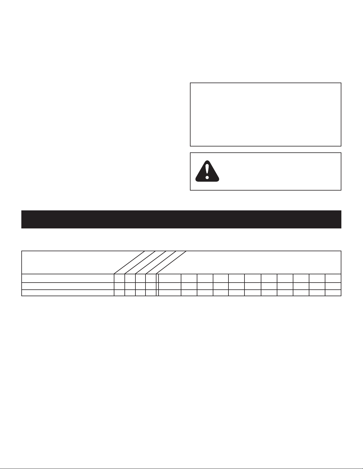
CAUTION: Wear eye protection, gloves
and protective clothing when handling
and working with lawn chemicals.
MAINTENANCE/STORAGE
CUSTOMER RESPONSIBILITIES
• Read and follow the maintenance schedule and the maintenance procedures listed in this section.
MAINTENANCE SCHEDULE
Fill in dates as you
complete regular service.
Check for loose fasteners X
Clean tank X
Lubrication X
Before each use
Every season
After each use
Before storage
CHECK FOR LOOSE FASTENERS
• Before each use make a thorough visual check of
the sprayer for any bolts and nuts which may have
loosened. Retighten any loose bolts and nuts.
CLEANING TANK
• After use, ll the tank part way with water, start the
sprayer and allow clear water to be pumped through
the plumbing system and out through the boom
assembly and the handgun. Use the handgun to
thoroughly wash all internal parts of the tank, the
outside of the tank and the boom.
• Rell the tank about half full with plain water and
a chemical neutralizer and repeat the cleaning
instructions above. Flush the entire sprayer with the
neutralizing agent. Follow the chemical manufacturers
instructions for disposal of all wash or rinsing water.
LUBRICATION
• Oil the wheels at least once a season.
CLEANING STRAINERS
• Periodically clean the strainer in the end of the intake
hose at the bottom of the tank. Remove the nylon
swivel nut from the hose, pull out the screen and ush
it with clear water.
• Periodically clean the strainers in the boom nozzles.
Remove the nozzle, pull out the screen and ush it
with clear water.
STORING
• Drain all water out of the sprayer, paying special
attention to the pump and handgun. These items
are especially prone to damage from chemicals and
freezing weather.
• The sprayer should be winterized before storage by
pumping a 50-50 solution of water and R. V. antifreeze
through the entire plumbing. Proper care and
maintenance will prolong the life of the sprayer.
8
Service Dates
Page 9
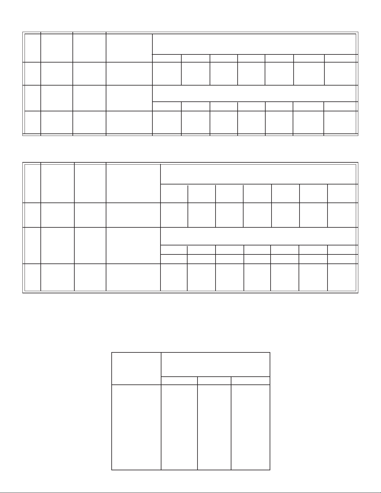
U.S. GALLON TIP CHART
Tip Spray Pressure Tip Capacity GALLONS PER ACRE (BASED ON WATER)
No. Width PSI US Gallons
Inches Per Minute 1 MPH 2 MPH 3 MPH 4 MPH 5 MPH 7.5 MPH 10 MPH
#3 80" 25 .36 53 26.5 17.7 13.3 10.6 7.1 5.3
Tip Spray Pressure Tip Capacity GALLONS PER 1000 SQ. FT. (BASED ON WATER)
No. Width PSI U.S. Gallons
Inches Per Minute 1 MPH 2 MPH 3 MPH 4 MPH 5 MPH 7.5 MPH 10 MPH
#3 80" 25 .36 1.22 0.6 0.41 0.31 0.24 0.16 0.12
IMPERIAL GALLON (LITER) TIP CHART
Tip Spray Pressure Tip Capacity
No. Width PSI Imperial Gallons
Inches (Bar) per minute 1 MPH 2 MPH 3 MPH 4 MPH 5 MPH 7.5 MPH 10 MPH
(mm) (liters per minute) 1.6 K/H 3.2 K/H 4.8 K/H 6.4 K/H 8 K/H 12 K/H 16 K/H
#3 80" 25 .30 44.2 22.1 14.8 11.1 8.9 5.9 4.4
(2032 mm) (1.75) (1.36) (201.0) (100.5) (67.8) (50.5) (40.5) (26.8) (20.0)
Jet Spray Pressure Tip Capacity
Size Width PSI Imperial Gallons
Inches (Bar) per minute 1 MPH 2 MPH 3 MPH 4 MPH 5 MPH 7.5 MPH 10 MPH
(mm) (liters per minute) 1.6 K/H 3.2 K/H 4.8 K/H 6.4 K/H 8 K/H 12 K/H 16 K/H
#3 80" 25 .30 1.0 0.50 0.34 0.26 0.20 0.14 0.10
(2032 mm) (1.75) (1.36) (4.54) (2.27) (1.55) (1.18) (0.91) (0.64) (0.54)
IMPERIAL GALLONS (Liters) PER ACRE (BASED ON WATER)
IMPERIAL GALLONS (Liters) PER 1000 SQ. FT. (BASED ON WATER)
GROUND SPEED CHART
M.P.H. (K/H) Time Required in Seconds to
Travel a Distance of:
1.0 (1.6) 68 136 205
2.0 (3.2) 34 68 102
3.0 (4.8) 23 45 68
4.0 (6.4) 17 34 51
5.0 (8.0) 14 27 41
6.0 (9.7) 11 23 34
7.0 (11.3) 9.7 19 29
8.0 (12.9) 8.5 17 26
9.0 (14.5) 7.6 15 23
10.0 (16.1) 6.8 14 20
100 ft (30.5 M) 200 ft (61 M) 300 ft (91.5 M)
9
Page 10
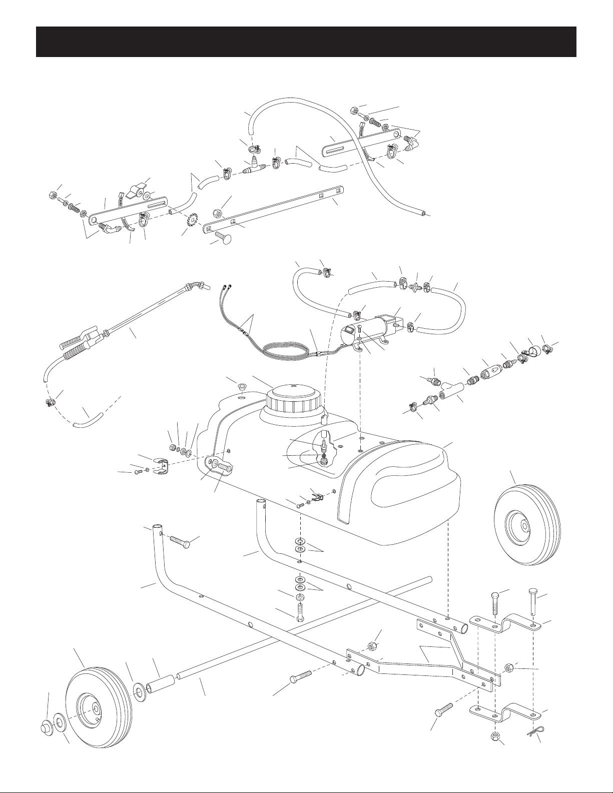
PARTS
34
A
25
32
26
2
60
4
9
10
37
44
27
43
36
42
39
41
40
57
12
27
38
27
36
43
42
27
39
41
40
12
27
64
55
46
D
5
19
7
35
1
B
B
C
A
C
3
6
6
27
27
21
8
20
23
23
24
28
59
61
32
27
27
27
27
13
18
14
15
16
17
52
56
54
56
54
53
31
44
63
49
47
33
30
31
48
57
62
C
63
29
63
44
63
34
51
50
50
58
45
11
22
57
29
REPAIR PARTS FOR 15 GALLON SPRAYER MODEL 486.245313
10
Page 11
REPAIR PARTS FOR 15 GALLON SPRAYER MODEL 486.245313
REF. PART NO. QTY. DESCRIPTION
1 49725 1 Tank (15 Gal.)
2 48297 1 Pump and Motor
3 45022 1 Hose, 1/2" ID (14" Lg.)
4 46287 1 Caplug Plug
5 45024 1 Strainer, Cap Type 1"
6 47002 2 Hose, 3/8" ID (10" Lg.)
7 45032 1 Nut, Swivel 3/4" Garden Hose
8 47005 1 Reducer, Hose Mender 1/2" x 3/8"
9 47078 4 Screw, Pan Hd. 10-24 x 3/4" Lg.
10 43910 4 Washer, Flat #10 SAE
11 46075 2 Terminal (not shown)
12 47392 2 Hose, 3/8" ID (20" Lg.)
13 47399 1 Drain Body
14 47398 1 Washer, Nylon
15 47402 1 Nut, Nylon 11/16" Thd.
16 47206 1 O-Ring
17 47403 1 Cap, Nylon 11/16" Thd.
18 45072 1 Gasket, 3/4" Garden Hose
19 46276 1 Adapter, 3/4" GH x 1/2" Barb
20 47411 1 Nipple (nylon) 1/4"
21 45025 1 Clamp, 1/2" (For Black Hose)
45026 1 Clamp, 3/8" (For Clear Hose)
22 45018 1 Connector with Wire
23 47412 2 Adapter (nylon) 1/4" x 3/8"
24 47413 1 Clamp, Conduit
25 47406 1 Spray Gun
26 49761 1 Hose, 1/4" ID (15' Lg)
27 45026 11 Clamp, 3/8" (For Black Hose)
47405 11 Clamp, 1/4" (For Clear Hose)
28 47415 1 Tee, Nylon 1/4" NPT.
29 48296 2 Frame Tube
30 24860 2 Hitch Arm
31 23014 2 Hitch Bracket
32 49779 1 Coiled Hose Clamp
REF. PART NO. QTY. DESCRIPTION
33 24584 1 Axle, 1/2"
34 46503 2 Wheel
35 46700 1 Lid
36 24122 2 Boom Bar
37 24585 1 Bracket, Boom Mount
38 47394 1 Tee, Plastic 3/8" Hose
39 45028 2 Nozzle, SS Floodjet
40 45029 2 Strainer, Screen Type
41 45037 2 Nut, Screen Body
42 47396 2 Elbow, Plastic 11/16" Thd.
43 726-0178 2 Nylon Tie
44 44180 8 Bolt, Hex 5/16-18 x 2"
45 43840 2 Bolt, Hex 5/16-18 x 1-1/4"
46 44732 2 Washer, Tooth Lock 5/16"
47 47623 1 Hitch Pin
48 43086 4 Lock Washer, 5/16"
49 43343 1 Pin, Hair Cotter #4 (1/8")
50
R19171616
51 44166 2 Hub Cap (1/2" Palnut)
52 47397 1 Clip (Large), Spray Gun
53 45180 1 Clip (Small), Spray Gun
54 736-0722 2 Lock Washer, #10
55 43682 2 Bolt, Carriage 5/16-18 x 1-1/4"
56 45040 2 Screw, Phillips Hd. #10-24 x 1/2"
57 43081 18 Washer, 5/16" Std. Wrt.
58 46578 2 Spacer
59 47416 1 Valve, Nylon 1/4"
60 47421 1 Hose, 3/8" ID (28" Lg.)
61 47414 1 Adapter, 1/4" NPT x 1/4" Barb
62 43084 4 Bolt, Hex 5/16-18 x 1-3/4"
63 47810 10 Nut, Nylock Hex 5/16-18
64 712-0421 2 Knob
41054 1 Owners Manual
4 Washer, 17/32" x 1"
11
Page 12

® Registered Trademark / TM Trademark /SM Service Mark of Sears Brands, LLC
® Marca Registrada / TM Marca de Fábrica / SM Marca de Servicio de Sears Brands, LLC
MC
Marque de commerce / MD Marque déposée de Sears Brands, LLC © Sears Brands, LLC
Get it fixed, at your home or ours!
Your Home
For repair – in your home – of all major brand appliances,
lawn and garden equipment, or heating and cooling systems,
no matter who made it, no matter who sold it!
For the replacement parts, accessories and
owner’s manuals that you need to do-it-yourself.
For Sears professional installation of home appliances
and items like garage door openers and water heaters.
1-800-4-MY-HOME
®
(1-800-469-4663)
Call anytime, day or night (U.S.A. and Canada)
www.sears.com www.sears.ca
For expert home solutions advice: www.managemyhome.com
Our Home
For repair of carry-in items like vacuums, lawn equipment,
and electronics, call or go on-line for the location of your nearest
Sears Parts & Repair Service Center
1-800-488-1222 (U.S.A.) 1-800-469-4663 (Canada)
Call anytime, day or night
www.sears.com www.sears.ca
To purchase a protection agreement on a product serviced by Sears:
1-800-827-6655 (U.S.A.) 1-800-361-6665 (Canada)
Para pedir servicio de reparación
a domicilio, y para ordenar piezas:
1-888-SU-HOGAR
®
(1-888-784-6427)
Au Canada pour service en français:
1-800-LE-FOYER
MC
(1-800-533-6937)
www.sears.ca
 Loading...