

Page 1
owners
manual
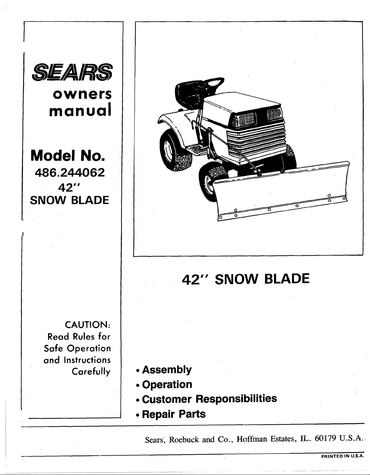
Model No.
486.244062
42""
SNOW BLADE
CAUTION:
Read Rules for
Safe Operation
and Instructions
Carefully
42"" SNOW BLADE
• Assembly
• Operation
• Customer Responsibilities
• Repair Parts
Sears; Roebuck and Co., Hoffman Estates, IL. 60179 U.S.A.
PRINTED IN U.S.A.
Page 2
RULES FOR SAFE OPERATIONS
Any power equipment can cause injury if operated improperly or if the user does not understand how to operate
the equipment.
LOOK FOR THIS SYMBOL TO POINT OUT
IMPORTANT SAFETY PRECAUTIONS, IT MEANS
-- ATTENTION! BECOME ALERTJ YOUR SAFETY IS
INVOLVED,
Exercise caution at all times, when using power equipment.
1. Read the tractor and snow blade owners manuals and know how to operate your tractor before using
tractor with snow blade attachment.
2. Never operate tractor and snow blade without wearing proper clothing suited to weather conditions and
operation of controls.
3. Never allow children to operate tractor and snow blade, and do not allow adults to operate without proper
instructions.
4.. Always begin with transmission in first (low) gear and gradually increase speed as required.
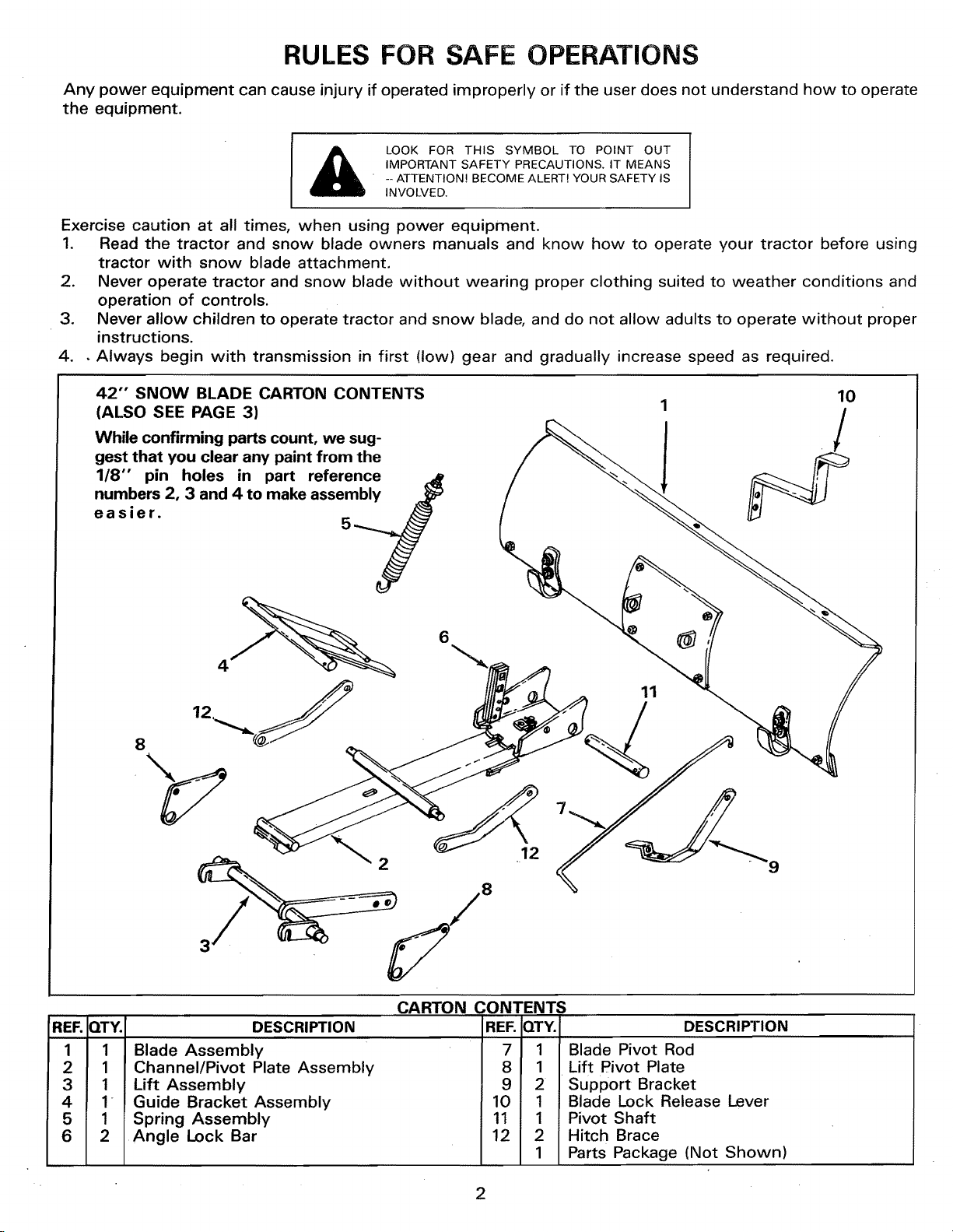
42"" SNOW BLADE CARTON CONTENTS
(ALSO SEE PAGE 3)
While confirming parts count, we sug-
gest that you clear any paint from the
1/8" pin holes in part reference
numbers 2, 3 and 4 to make assembly
easier.
10
6
11
REF. QTY.
1 1
2 1
3 1
4 1
5 1
6 2
3
DESCRIPTION
Blade Assembly
Channel/Pivot Plate Assembly
Lift Assembly
Guide Bracket Assembly
Spring Assembly
Angle Lock Bar
12
CARTON CONTENTS
REF. QTY.i DESCRIPTION
7 1
8 1
9 2
10 1
11 1
12 2
1
2
9
Blade Pivot Rod
Lift Pivot Plate
Support Bracket
Blade Lock Release Lever
Pivot Shaft
Hitch Brace
Parts Package (Not Shown)
Page 3
U
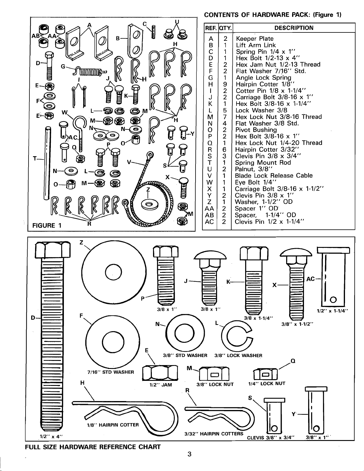
CONTENTS OF HARDWARE PACK: (Figure 1)
REF, QTY. DESCRIPTION
FIGURE 1
H
R
A 2 Keeper Plate
B 1 Lift Arm Link
C 1 Spring Pin 1/4 x 1"
D 1 Hex Bolt 1/2-13 x 4"
E 2 Hex Jam Nut 1/2-13 Thread
F 2 Flat Washer 7/.16" Std.
G 1 Angle Lock Spring
H 9 Hairpin Cotter 1/8"
I 2 Cotter Pin 1/8 x 1-1/4"
J 2 Carriage Bolt 3/8-16 x 1"
K 1 Hex Bolt 3/8-16 x 1-1/4"
L 5 Lock Washer 3/8
M 7 Hex Lock Nut 3/8-16 Thread
N 4 Flat Washer 3/8 Std.
O 2 Pivot Bushing
P 2 Hex Bolt 3/8-16 x 1"
Q 1 Hex Lock Nut 1/4-20 Thread
R 6 Hairpin Cotter 3/32"
S 3 Clevis Pin 3/8 x 3/4"
T 1 Spring Mount Rod
U 2 Palnut, 3/8"
V 1 Blade Lock Release Cable
W 1 Eye Bolt 1/4"
X 1 Carriage Bolt 3/8-16 x 1-1/2"
Y 2 Clevis Pin 3/8 x 1"
Z 1 Washer, 1-1/2" OD
AA 2 Spacer 1" OD
AB 2 Spacer, 1-1/4" OD
AC 2 Clevis Pin 1/2 x 1-1/4"
Z
3/8 x 1" 3/8 x 1"
3/8"" x 1-1/2""
3/8" STD WASHER 3/8'" LOCK WASHER
H 112- JAM 3/8" LOCK NUT 1/4" LOCK NUT
" Q
\ \ '
y._
1/2" x 4"
FULL SIZE HARDWARE REFERENCE CHART
3/32" HAIRPIN COTTERS
3
CLEVIS 3/8" x 3/4"
0
m
3/8"" x 1";"
Page 4
ASSEMBLY INSTRUCTIONS
TOOLS REQUIRED FOR ASSEMBLY
(1) Pliers
(1) Hammer
(1) 7/16" Open End or Box Wrench
(1) 1/2'3 Open End or Box Wrench
(1) 9/16" Open End or Box Wrench
(1) 3/4" Open End or Box Wrench
(1) Adjustable Wrench
Refer to carton contents figure on page 2 and figure
1 on page 3 for parts and hardware needed to
assemble snow blade.
RIGHT HAND (R.H.) AND LEFT HAND
(L.H.) ARE DETERMINED FROM
OPERATOR'S POSITION WHILE
SEATED ON TRACTOR.
.
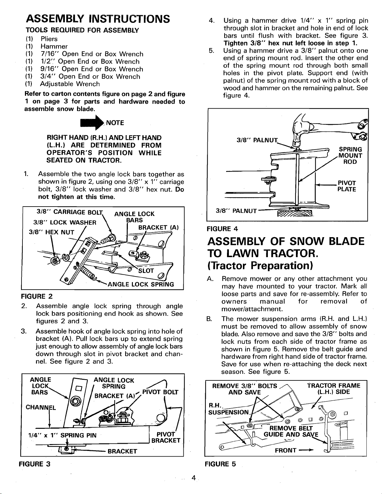
Assemble the two angle lock bars together as
shown in figure 2, using one 3/8" x 1" carriage
bolt, 3/8" lock washer and 3/8" hex nut. Do
not tighten at this time.
.
Using a hammer drive 1/4" x 1"' spring pin
through slot in bracket and hole in end of lock
bars until flush with bracket. See figure 3.
Tighten 3/8"" hex nut left loose in step 1.
.
Using a hammer drive a 3/8" palnut onto one
end of spring mount rod. Insert the other end
Of the spring mount rod through both small
holes in the pivot plate. Support end (with
palnut) of the spring mount rod with a block of
wood and hammer on the remaining palnut. See
figure 4.
3,8
.MouNT
3/8"" CARRIAGE BOLT\ ANGLE LOCK
3/8" LOCK WASHER \ BARS
/ _ I BRACKET (A)
3/8" HEX NUT / _ /______/=========_
/'_ "_ANGLE LOCK SP_'NG
FIGURE 2
2. Assemble angle lock spring through angle
lock bars positioning end hook as shown. See
figures 2 and 3.
3. Assemble hook of angle lock spring into hole of
bracket (A). Pull lock bars up to extend spring
just enough to allow assembly of angle lock bars
down through slot in pivot bracket and chan-
nel. See figure 2 and 3.
ANGLE ANGLE LOCK
LocK.. 3
BARS _,_ (A). PIVOT BOLT
3/8" PALNUT =-_=
FIGURE 4
ASSEMBLY OF SNOW BLADE
TO LAWN TRACTOR.
(Tractor Preparation)
A=
Remove mower or any other attachment you
may have mounted to your tractor. Mark all
loose parts and save for re-assembly. Refer to
owners manual for removal of
mower/attachment.
g.
The mower suspension arms (R.H. and L.H.)
must be removed to allow assembly of snow
blade. Also remove and save the 3/8" bolts and
lock nuts from each side of tractor frame as
shown in figure 5. Remove the belt guide and
hardware from right hand side of tractor frame.
Save for use when re-attaching the deck next
season. See figure 5.
REMOVE 3/8"' BOLTS _ TRACTOR FRAME
AND SAVE _ (L.H.) SIDE
/>,.//\\
R.H. __[ _ _---X _-_
1/4" x 1" SPRING PIN
FIGURE 3 FIGURE 5
=
' _ ' - BRACKET
PIVOT
-- 4,
_.__UIDE AND SAVE I\ I I
FRONT _
Page 5
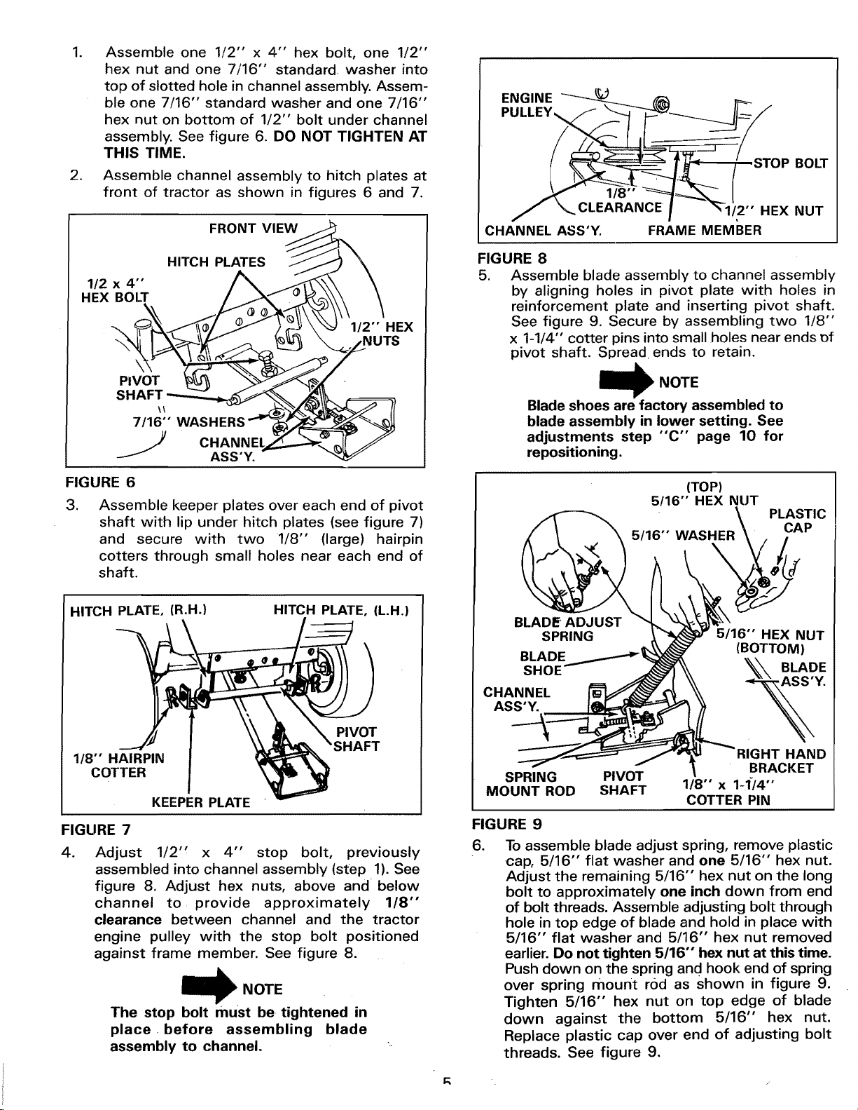
.
Assemble one 1/2" x 4" hex bolt, one 1/2"
hex nut and one 7/16" standard washer into
top of slotted hole in channel assembly. Assem-
ble one 7/16" standard washer and one 7/16"
hex nut on bottom of 1/2" bolt under channel
assembly. See figure 6. DO NOT TIGHTEN AT
THIS TIME.
.
Assemble channel assembly to hitch plates at
front of tractor as shown in figures 6 and 7.
FRONT VIEW
ENGINE
PULLEY,,,,
BOLT
1/8"
CLEARANCE 1/2"" HEX NUT
CHANNEL ASS'Y, FRAME MEMBER
HITCH PLATES
1/2 x 4"
HEX BOLT
PIVOT
\\
7/16" WASHERS
ASS'Y.
FIGURE 6
.
Assemble keeper plates over each end of pivot
shaft with lip under hitch plates (see figure 7)
and secure with two 1/8" (large) hairpin
cotters through small holes near each end of
shaft.
HITCH PLATE, (R.H.)
HITCH PLATE, (L.H.)
1/2'" HEX
FIGURE 8
5. Assemble blade assembly to channel assembly
by aligning holes in pivot plate with holes in
reinforcement plate and inserting pivot shaft.
See figure 9. Secure by assembling two 1/8"
x 1-1/4" cotter pins into small holes near ends t)f
pivot shaft. Spread ends to retain.
NOTE
Blade shoes are factory assembled to
blade assembly in lower setting. See
adjustments step "'C'" page 10 for
repositioning.
(TOP)
5/16"' HEX NUT
PLASTIC
CAP
BLADE ADJUST
SPRING
BLADE
5/16"" HEX NUT
(BOTTOM)
SHOE
CHANNEL
ASS'Y.
1/8"" HAIRPIN
COTTER
KEEPER PLATE
FIGURE 7
.
Adjust 1/2" x 4" stop bolt, previously
assembled into channel assembly (step 1). See
figure 8. Adjust hex nuts, above and below
channel to provide approximately 1/8"
clearance between channel and the tractor
engine pulley with the stop bolt positioned
against frame member. See figure 8.
NOTE
The stop bolt must be tightened in
place before blade
assembly to channel.
PIVOT
&FT
SPRING PIVOT
MOUNT ROD SHAFT
118" x 1-1"/4'"
COTTER PIN
BRACKET
FIGURE 9
.
To assemble blade adjust spring, remove plastic
cap, 5/16" flat washer and one 5/16" hex nut.
Adjust the remaining 5/16" hex nut on the long
bolt to approximately one inch down from end
of bolt threads. Assemble adjusting bolt through
hole in top edge of blade and hold in place with
5/16" flat washer and 5/16" hex nut removed
earlier. Do not tighten 5/16" hex nut at this time.
Push down on the spring and hook end of spring
over spring mount rod as shown in figure 9.
Tighten 5/16" hex nut on top edge of blade
down against the bottom 5/16" hex nut.
Replace plastic cap over end of adjusting bolt
threads. See figure 9,
3HT HAND
Page 6

.
Assemble one lift pivot plate under left hand foot
rest and outside of frame. Secure front of lift
pivot plate with one 3/8" x 1" c_levis pin, 3/8"
flat washer and 3/32" (small) hairpin cotter.
Secure rear of lift pivot plate with one 3/8" x
3/4" clevis pin and one 3/32" (small) hairpin
cotter. DO NOT ASSEMBLE LiFT PIVOT PLATE
UNDER THE RIGHT HAND FOOT REST AT THIS
TIME.
.
Assemble one 3/8" x 1-1/4" hex bolt through
3/8" flat washer, through pivot bushing,
through large hole in lift arm link near angle end
and through hole in long arm nearest the end.
Secure with one 3/8" lock washer and one 3/8"
hex nut. See figure 12. NOTE: Lift arm link must
pivot freely.
•_ FRONT LEFT HAND
FRAI_E _ CLEVIS PIN
..... _'.'_ ', _, \_ll FOOT REST
._/_ x ]-" __ _ (LEFT HAND)
LIFT PIVOT PLATE _ _,
FIGURE 10
FRONT (L.H.) SIDE VIEW
c_
l=l
3/32" HAIR PIN
COTTERS
-_ _ -"3/8" FLAT WASHER
;T HAND FOOT REST
SIDE VIEW
LIFT PIVOT PLATE
,
NOTE
Lift arm link must be positioned as
shown in figures 12 and 13.
10.
Assemble one 3/8" x 1" hex bolt through
second hole from end of long arm. Secure with
one 3/8" lock washer and one 3/8" hex nut.
This bolt is used as a limit stop for the lift arm
link. See figure 13.
11.
Move attachment lift lever all the way forward
and lock in position. See figure 20, page 9.
12.
Hook lift assembly arms over both link rods,
assemble lift arm link over channel rod and
secure with one 1/8" (large) hairpin cotter. See
figure 13.
13.
Assemble one hitch brace (endwiththe large
hole), one 1-1/4" OD spacer onto each end of
the lift assembly pivot shaft. See figure 14.
14.
Insert pivot shaft end (from R.H. side of tractor)
into hole in L.H. lift pivot mount plate. See figure
14.
FIGURE 11
8. Pre-assemble lift arm link to inside of long arm
on lift assembly. As shown in figure 12.
3/8" x 1-1/4"_.=_ 3
HEX BOLT
I.IFT ASSEMBLY
LONG ARM
3/8" LOCK WASHER
FIGURE 12 FIGURE 13
" FLAT WASHER
_BU PIVOT
,_LIFT ARM
\
SHING
LINK
318" HEX
/
SHAFT END
LIFT PIVOT MOUNT PLATE
.
RIGHT HAND SIDE VIEW
FRONT_
3/8'" x 1" HEX BOLT
3/8" LOCK WASHER
3/8" HEX NUT
LIFT ARM LINK
CHANNEL
ROD
\
LIFT
HAIRPIN
COTTER
Page 7

L.H. LIFT PIVOT
MOUNT PLATE
Assemble the front end of each hitch brace
16.
to the rear hole in each hitch plate using one
1/2" x 1-1/4" clevis pin, one 1" OD spacer and
one 1/8" hairpin cotter. See figure 16.
HITCH" PLATE
HAIRPIN COTTER
LIFT ASSEMBLY
PIVOT SHAFT
FIGURE 14
15.
Assemble the other lift pivot plate, over right
hand end of lift assembly pivot shaft and
connect to outside of frame (see figure 15)
using one 3/8" x 1" clevis pin from inside
through front hole in lift pivot plate. Secure with
3/8" flat washer and 3/32"" (small) hairpin
cotter. Secure rear of plate with one 3/8" x 3/4"
clevis pin and one 3/32" (small) hairpin cotter.
Secure ends of pivot shaft to each lift pivot plate
with 1/8" (large) hairpin cotter. See figures 14
and 15.
HITCH BRACE
1-1/4" OD SPACER
1" OD SPACER 1/_'; x 1-i/4"
HITCH BRACE CLEVIS PIN
FIGURE 16
17. Assemble guide bracket assembly shaft end
into the left hand hitch plate. See figure 17. Slide
guide assembly back to the right and into hole
of the right hand hitch plate. Secure with a 1/8"
(large) hairpin cotter in each end. See figure 17.
Lower front end of guide bracket assembly to
straddle channel assembly.
3/32"" 318"" X 3/4'" CLEVIS PINS
HAIRPIN
COTTER-------_ 3/8"
J ._ FLAT WASHER
LI
ROD ,
LIFT ASS'Y. _ LIFT PIVOT
PIVOT SHAFT MOUNT PLATE
RIGHT HAND SIDE VIEW
FIGURE 15
FRONT --_
_ I FRONT PIVOT SHAFT
HITCH ! 1/R-'
PLATE (R.H.) I HAIRPI_I_coTTER
• i
• T
[ / GUIDE BRAICKET ASS,Y.PLATE''/'__'_ ' HITC(L H )
FIGURE 17
Page 8

18.
Raise hood and remove 3/8" carriage bolt and
nut from right hand side of frame. See figure 18.
LIFT
LEVER
. PLUNGER
REMOVE FRONT
CARRIAGE BOLT
AND NUT
23. Secure one end of blade lock release cable to
small hole in blade lock release lever using one
3/8" x 3/4" clevis pin and one 3/32" hairpin
cotter• See figure 20.
BLADE LOCK
RELEASE LEVER
1-1/2" O D WASHER
3/8" x 1"
HEX BOLT
D
RIGHT SIDE VIEW
FIGURE 18
!9. Assemble support bracket onto right hand side
of tractor frame (where carriage bolt was
removed in step 15) using 3/8" x 1"" carriage
bolt inside of frame and secure with 3/8" lock
washer and 3/8" hex nut, on outside of frame.
See figure 19.
ATTACHMENT
LIFT LEVER
3/8"'x 1"
CARRIAGE EYE BOLT
BOLT HAIRPIN
3/8" LOCK COTTER
WASHER 3/8" HEX NUT
FIGURE 19
20. Assemble the 1/4" eye bolt at the top of the
support bracket and secure with one 1/4'" hex
. lock nut. See figure 19.
21. Assemble blade pivot rod through 1/4" eye
bolt as shown in figure 19. Secure lower end
of blade pivot rod through hole on right hand
side of blade assembly with small hairpin
cotter. See figure 19.
22. Assemble blade lock release lever to right side
of tractor frame using one 1-1/2" OD washer,
one 3/8" x 1" hex bolt, spacer, 3/8" flat washer
and secure tightly with one 3/8" hex lock nut.
See figure 20.
LIFT LEVER FRONT---_
PLUNGER
BLADE PIVOT
1/4" HEX LOCK ROD
RIGHT SIDE VIEW
CLEVIS PIN
COTTER PIN
SPACER
FLAT WASHER
3/8" HEX LOCK NUT
FIGURE 20
24. Thread cable toward front of tractor under
steering tie rod and front axle and above guide
bracket assembly• See figure 21.
25.
Assemble one 3/8" x 1-1/2" carriage bolt into
top hole in angle lock bars and tighten secure-
ly with one 3/8" hex lock nut. Place free end
of cable over threaded end of carriage bolt and
retain loosely with 3/8" hex lock nut. See figure
21.
RIGHT SIDE VIEW
SUPPORT BRACKET
3/8"" x 1-1/2"' CARRIAGE BOLT
NUTS (2)
FRONT .
il
STEERING
TIE ROD
CHANNEL
ASS'Y.
FIGURE 21
FREE END
OF CABLE
GUIDE BRACKET
ASS'Y.
Q
Page 9

OPERATION INSTRUCTIONS
AND ADJUSTMENTS
The snow blade attachement is designed to move
new loose snow in depths up to 6" - 8'".
SUDDEN STOPS OR CHANGE IN
HIDDEN OBJECTS CAN CAUSE
DIRECTION.
CONTROLS
Become familiar with all of the controls and
adjustments on the tractor and sn.ow blade
before operating. Refer to tractor owner's manual for
tractor controls. Controls for operating snow blade
are as follows:
A,
Attachment lift lever:
Located on right hand side of tractor. See figure
22. Move lever forward to lower snow blade. Pull
lever back to raise and lock snow blade.
B.
Lift lever plunger:
Located on top of attachment lift lever. See
figure 22. Pull back on attachment lift lever and
depress plunger to release.
WITH THE SNOW BLADE IN THE "'UP"
POSITION DO NOT DEPRESS THE
PLUNGER WITHOUT HOLDING BACK
ON THE LIFT CONTROL LEVER OR
SNOW BLADE MAY SUDDENLY DROP.
C.
Attachment depth control knob:
Adjust attachment lift lever movement with
attachment DEPTH CONTROL KNOB (See
figure 22) for maximum movement between
locking notches and to prevent lever from lock-
ing in the down lock notch. See figure 22 .
NOTE
Some tractors are equipped with
depth control notches instead of a
depth control knob. See below.
Attachment depth control notches: (some models)
To adjust your snow blade to the best operating
height, depress plunger on attachment lift lever,
select one of six settings and release plunger.
D. Blade lock release:
Located on the right hand side of tractor at front
of foot rest. See figur e 22. Raise blade to
transport position. Push forward on the blade
lock release lever (with right foot) and hold while
pushing or pulling on the blade pivot rod to move
snow blade angle to left, center and right.
Remove foot from blade lock release lever to
lock blade into position.
FIGURE 22
LIFT LEVER
DEPTH CONTROL KNOB
LOCK DOWN
ATTACHMENT
NOTCH
ATTACHMENT LIFT
LEVER
BLADE LOCK
RELEASE LEVER
BLADE
PIVOT ROD
BLADE
ADJUST SPRING
BLADE SHOE
ALTERNATE DESIGN SIX NOTCHES
(NO DEPTH CONTROL KNOB)
9
Page 10

ADJUSTMENT
A.
Blade angle lock bars:
Blade angle can be adjusted at the blade pivot
in front of tractor by first raising the blade to
transport position, pull back on angle lock bars
to release the blade and pivot to the right,
center, or left positions. Release lock bars to
lock.
To adjust blade angle from the tractor seat:
Raise blade to transport position. Push forward
on the blade lock release lever (with right foot)
and hold while pushing or pulling on the blade
pivot rod to move snow blade angle to left,
center and right. Remove foot from blade lock
release lever to lock blade into position.
B.
Adjust blade spring:
Blade adjust spring tension is adjustable to
permit blade to tilt forward to by-pass solid
obstructions.
KNOW THE TERRAIN. AVOID
EXCEPTIONALLY SHARP SLOPES OR
DROPOFFS WHICH MAY BE HIDDEN
BY THE SNOW.
NEVER RUN THE SNOW BLADE
INTO HEAVY MATERIAL AT HIGH
SPEED.
C.
Blade shoe adjustment:
Blade shoes on ends of blade, (see figure 22),
may be raised for close work on smooth sur-
faces or lowered to raise the blade to work on
rough or uneven areas. Make sure both shoes
are set evenly and nuts are tightened securely.
_NOTE
Wheel weights and tire chains must
be used with your snow blade for
traction. These accessories are
available at your nearest Sears retail
or catalog store. See page 12.
OPERATION
3. DO NOT push snow in the same direction
causing excessive build up with each succesive
pass.
4. If blade is stored in heated area, allow lawn
tractor and blade to adjust to outdoor
temperature before operating to reduce icing on
the metal surfaces.
GROUND BEFORE LEAVING
ALWAYS LOWER BLADE TO
TRACTOR.
TO REMOVE SNOW BLADE
FROM TRACTOR
1. Lower blade to ground with blade in the center
(straight) position.
2. Refer to figure 23 below and;
A.
Remove 1/8" hairpin cotter from the lift
arm link and channel assembly.
B.
Remove 3/32" (small) hairpin cotters from
right hand and left hand lift pivot plates,
remove two 3/8" clevis pins from each
side of frame, unhook and lower the lift
assembly to the ground.
C.
Re-assemble one 3/8"-16 x 3/4 carriage
bolt and 3/8" hex nut in hole labeled A and
B in figure 23 on each side of tractor frame.
Also see figure 5 on page 4.
D. The belt guide must be re-assembled
to right hand side of tractor frame. See
figure 5 on page 4.
3/32'" HAIRPIN
INSPECT THE AREA TO BE WORKED
CAREFULLY BEFORE OPERATING
THE SNOW BLADE. AVOID PIPES,
ROOTS, CURBS'OR OTHER HEAVY
OBSTRUCTIONS.•
.
Prepare lawn tractor engine for cold weather
use following instructions furnished with lawn
tractor.
.
Always begin with transmission in first (low)
gear and gradually increase speed as required.
MOUNT PLATE (R.H.I
RIGHT HAND SIDE VIEW FRONT----_
FIGURE 23
lt"t
Page 11

E.
Re-install suspension arms removed on
page 4. See figure 5 on page 4.
CAUTION: If the suspension arms
are ever removed from tractor
(which may be necessary for
mounting other attachments) the
lift link on the LEFT side of the trac-
tor must be removed from tractor
if it is not needed or used with the
attachment. Refer also to tractor
manual. Failure to do so will allow
the lift link to interfere with tractor
steering which could cause loss of
control while driving resulting in
property damage and/or personal
injury.
.
Refer to figure 24 and remove 1/8" (large)
hairpin cotters from ends of channel assembly
pivot shaft and remove keeper plates. Lift the
channel assembly pivot shaft out of the hitch
plates and lower channel to the ground.
CUSTOMER RESPONSIBILITIES
During the operating season, check all bolts, nuts and
hairpin cotters to be sure they are secure. For
improved snow removal performance, coat the blade
with automotive type paste wax.
LUBRICATION
Oil all pivot points so that they will work freely.
STORAGE
3_
Refer to figure 24 below and remove t/8" (large)
hairpin cotters from ends of guide bracket
assembly and remove guide bracket assembly.
r32"" HAIRPIN COTTER
1/8" HAIRPIN COTTERS
CLEVIS PIN
/
(R.H.)
HITCH
PLATE
KEEPER
PLATE CHANNEL
1/8" HAIRPIN PIVOT SHAFT BRACKET
COTTER ASS'Y.
ASS'Y. GUIDE
When the snow blade is not being used, remove all
dirt and rust and touch up with paint.
Apply a light coat of grease or rust preventative to
the blade and oil pivot points.
Store in an area where it is protected from weather.
FIGURE 24
.
Refer to figure 24 above and remove 3/32"
(small) hairpin cotter from 3/8" clevis pin which
holds end of blade lock release cable to blade
lock release lever. Pull cable free from tractor
and reassemble clevis pin and cotter pin for
storage. See figure 24.
.
Refer to figure 16 on page 7 and remove 1/8"
(large) hairpin cotter from each clevis pin that
holds each hitch brace in place. Remove hitch
braces and spacers. Reassemble clevis pin and
spacer to each hitch brace for storage.
11
Page 12

Attachments That Add to the Usefulness of Your
Craftsman Tractor
Sears offers a wide variety of attachments that fit your tractor. Many of these are listed below with brief
explanations of how they can help you. This list was current at the time of publication: however, it may change
in future years -- more attachments may be added, changes (including changes in the stock number) may be
made in these attachments, or some may be available.
Most of these attachments do not require additional hitches or conversion kits (those that do are indicated)
and are designed for easy attaching and detaching. You may order these attachments at most Sears retail stores,
catalog sales offices, and through the catalog.
TIRE CHAINS are heavy duty; closely-spaced, extra-large cross links give smooth ride, outstanding traction.
WHEEL WEIGHTS for rear wheels provide needed traction for snow removal or dozing heavy materials.
Weight (each)
30 lb.
33 lb.
A mounting bracket is available to mount one 55 pound weight on the rear of your tractor frame for added traction.
Lawn Tractors with 8 in. rims
Lawn or Yard Tractors with 10-in. rims
Fits
12
Page 13

13
Page 14

REPAIR PARTS FOR MODEL 486.244062--42" SNOW BLADE
25
€
7
3
46
3/* l.
¢
31
5
I
55
Page 15

REPAIR PARTS FOR MODEL 486,244062 -- 42'" SNOW BLADE
REF.
NO.
1
2
3
4
5
6
7
8
9
10
11
12
13
14
15
16
17
18
19
20
21
22
23
24
25
26
27
28
29
PART NO.
43080
43079
43064
43081
23863
23070
23117
62870
23131
43262
43349
62869
23855
23130
43263
44043
43083
43081
43331
23151
43069
43352
23122
23859
23856
62854
62868
43010
43348
QTY.
8
2
10
4
1
2
1
1
1
1
2
1
1
1
1
1
2
1
1
2
1
1
1
2
1
1
1
2
1
DESCRIPTION
Carriage Bolt 5/16-18 x 3/4"*
Carriage Bolt 5/16-18 x 1"*
Hex Lock Nut 5/16-18"
Washer 5/16 Std. Wrt.*
Blade 42"
Shoe
Wear Plate 42"
Reinforcement Plate Ass'y.
Special Pivot Bolt
Hex Lock Nut 1 /2-13"
Spring Pin 1/4 x 1"*
Channel Ass'y.
Pivot Plate Ass'y.
Spring Mount Bracket
Adjustment Spring
Hex Bolt 5/16-18 x 3-1/2 (special)
Hex Nut 5/16-18"
Washer 5/16 Std. Wrt.*
Plastic Cap
Angle Lock Bar
Carriage Bolt 3/8-16 x 1-1/2"
Washer 7/16" Std. Wrt.*
Pivot Shaft
Lift Pivot Plate
Spring Mount Rod
Lift Ass'y.
Guide Brk't Ass'y.
Cotter Pin 1/8 x 1-1/4"*
Angle Lock Spring
REF.
NO.
30
31
32
33
34
35
36
37
38
39
4O
41
42
43!
44
45_
46
471
48i
491
50J
_1 I
u . ,
531
54!
56!
57
PART NO.
45100
43350
43003
43082
43343
44917
43087
43070
43019
44044
43055
23857
43013
23624
23625
23631
44915
43352
43001
44419
44417
23745
45091
141
23896
44049
45133
45132
45134
QTY,
1
2
5
7
9
2
1
4
2
1
1
2
2
1
1
2
2
1
1
1
2
1
2
2
2
2
1
DESCRIPTION
Hex Bolt 1/2-13 x 4"*
Carriage Bolt 3/8-16 x 1"*
Spring Lock Washer 3/8"
Hex Lock Nut 3/8-16"
Hairpin Cotter 1/8"
Palnut, 3/8
Hex Bolt 3/8-16 x 1-1/4"*
Washer 3/8 Std. Wrt.*
Hex Jam Nut 1/2-13"
Clevis Pin 3/8 Dia. x 3/4" Lg.
.
Hairpin Cotter 3/32"
Pivot Release Lever
Hex Lock Nut 1/4-20 Thd.*
Keeper Plate
Pivot Bushing
Lift Arm Link
Blade Lock Release Cable
Washer 7/16 Std. Wrt.*
Hex Bolt 3/8-16 x 1"*
Eye Bolt 1/4-20
Blade Pivot Rod
Support Bracket
Clevis Pin 3/8" Dia. x 1" Lg.
Washer, 3/8 ID x 1-1/2" OD
Hitch Brace
Clevis Pin 1/2 Dia. x 1-1/4" Lg.
Spacer, 1/2" ID x 1" OD
Spacer, 1" ID x 1-1/4" OD
Owner's Manual
Sears, Roebuck and Co. reserves the right to make
any changes in design or improvements without
imposing any obligation to install the same upon its
items heretofore manufactured.
Page 16

owners
42"" SNOW BLADE
Always mention the Model Number when requesting service
or repair parts for your Snow Blade.
All parts listed herein may be ordered from any Sears Service
Center and most Sears stores.
manual
Model No.
486.244062
42""
SNOW BLADE
How to Order
Repair Parts
WHEN ORDERING REPAIR PARTS, ALWAYS GIVE THE
FOLLOWING INFORMATION:
• THE PART NUMBER
eTHE PART DESCRIPTION
eTHE MODEL NUMBER
eTRE NAME OF MERCHANDISE
If the parts you need are not stocked locally, your order will
be electronically transmitted to a Sears Repair Parts Distribu-
tion Center for handling.
LIMITED ONE YEAR WARRANTY
ON 42" SNOW BLADE
For one year from date of purchase, when this Snow Blade is
maintained and lubricated according to the operating and
maintenance instructions in the owner's manual, Sears will repair
free of charge any defect in material or workmanship.
If this Snow Blade is used for commercial or rental purposes, this
warranty applies for only 90 days from the date of purchase.
This warranty does not cover:
--repairs necessary because of operator abuse or negligence,
including the failure to maintain the equipment according to
instructions contained in the owner's manual.
WARRANTY SERVICE IS AVAILABLE BY RETURNING IT TO "I-HE
NEAREST SEARS SERVICE CENTER/DEPARTMENT IN THE
UNITED STATES.
This warranty applies only while this product is in use in the
United States.
This warranty gives you specific legal rights, and you may also
have other rights which vary from state to state.
Sears, Roebuck and Co. Di817WA, Hoffman Estates, IL. 60179
Sears, Roebuck and Co., Hoffman Estates, IL. 60179 U.S.A.
l::r11_i_A-iMr_ _I_P-,I":IA lR_w llQ_t PRINTED IN U.S.A.
 Loading...