

Page 1
Operator's Manual
®
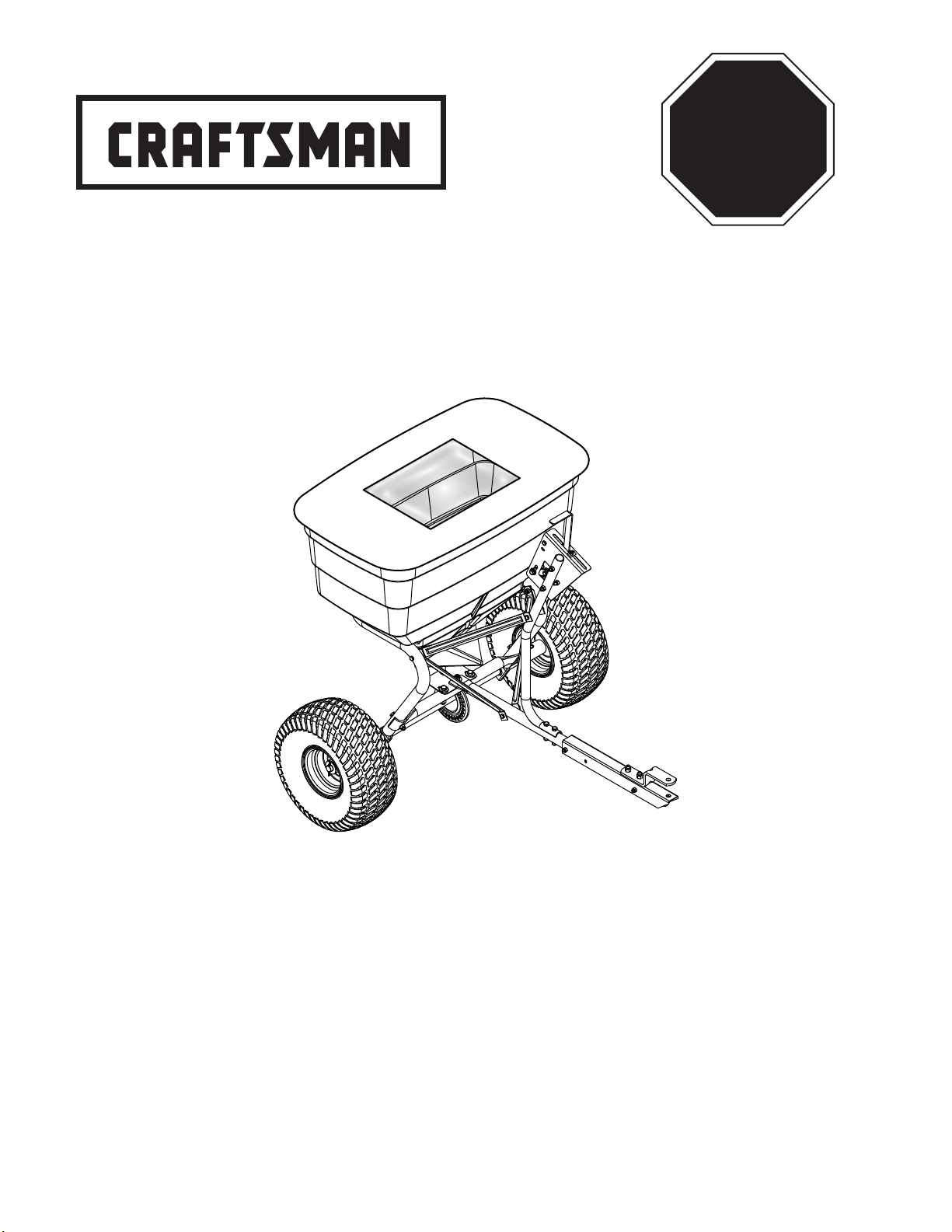
BROADCAST SPREADER
Model No. 486.24009
STOP
DO NOT RETURN TO STORE
For Missing Parts or Assembly
Questions Call 1-866-576-8388
CAUTION:
Before using this product, read
this manual and follow all Safety
Rules and Operating Instructions.
• Safety
• Assembly
• Operation
• Maintenance
• Parts
Sears Brands Management Corporation, Hoffman Estates, IL 60179 U.S.A.
www.sears.com/craftsman
PRINTED IN U.S.A. FORM NO. 42523 (09/07/12)
Page 2
TABLE OF CONTENTS
WARRANTY .................................................................... 2
SAFETY ........................................................................... 2
CARTON CONTENTS ..................................................... 3
ASSEMBLY ...................................................................... 4
OPERATION .................................................................... 7
MAINTENANCE .............................................................. 9
TROUBLESHOOTING ..................................................... 9
REPAIR PARTS ILLUSTRATION ................................... 10
REPAIR PARTS LIST ......................................................11
ORDERING REPLACEMENT PARTS ........... BACK PAGE
WARRANTY
CRAFTSMAN ONE YEAR FULL WARRANTY
FOR ONE YEAR from the date of purchase, this product is warranted against any defects in material or workmanship. A
defective product will be replaced free of charge.
For warranty coverage details to obtain free replacement, visit the web site: www.craftsman.com
This warranty is void if this product is ever used while providing commercial services or if rented to another person.
This warranty gives you specic legal rights, and you may also have other rights which vary from state to state.
Sears Brands Management Corporation, Hoffman Estates, IL 60179
DO NOT RETURN TO STORE for Missing Parts or Assembly Questions
Call 1-866-576-8388 Attachment Hotline
The model number and serial numbers will be found on a
decal attached to the [product name].
You should record both the serial number and the date of
purchase and keep in a safe place for future reference.
MODEL NUMBER: 486.24009
SERIAL NUMBER: __________________
DATE OF PURCHASE: __________________
SAFETY
Remember, any power equipment can cause injury if operated improperly or if the user does not understand how to
operate the equipment. Exercise caution at all times when using power equipment.
• Read the towing vehicle owners manual and towing
vehicle safety rules. Know how to operate your tractor
before using the broadcast spreader attachment.
• Read the chemical label instructions and cautions for
handling and applying the chemicals purchased for
spreading.
• Wear eye and hand protection when handling and
when applying lawn or garden chemicals.
• Never operate tractor and spreader attachment
without wearing substantial footwear, and do not
allow anyone to ride or sit on spreader attachment
frame.
• Never allow children to operate the tractor or spreader
attachment, and do not allow adults to operate
without proper instructions.
LOOK FOR THIS SYMBOL TO POINT OUT IMPORTANT SAFETY PRECAUTIONS. IT
MEANS — ATTENTION! BECOME ALERT! YOUR SAFETY IS INVOLVED.
• Always begin with the transmission in rst (low) gear
with the engine at low speed, and gradually increase
speed as conditions permit.
• When towing broadcast spreader do not drive too
close to a creek or ditch and be alert for holes and
other hazards which could cause you to lose control
of the broadcast spreader and tractor.
• Before operating vehicle on any grade (hill) refer
to the safety rules in the vehicle owner's manual
concerning safe operation on slopes. Stay off steep
slopes!
• Follow maintenance and lubrication instructions as
outlined in this manual.
2
Page 3
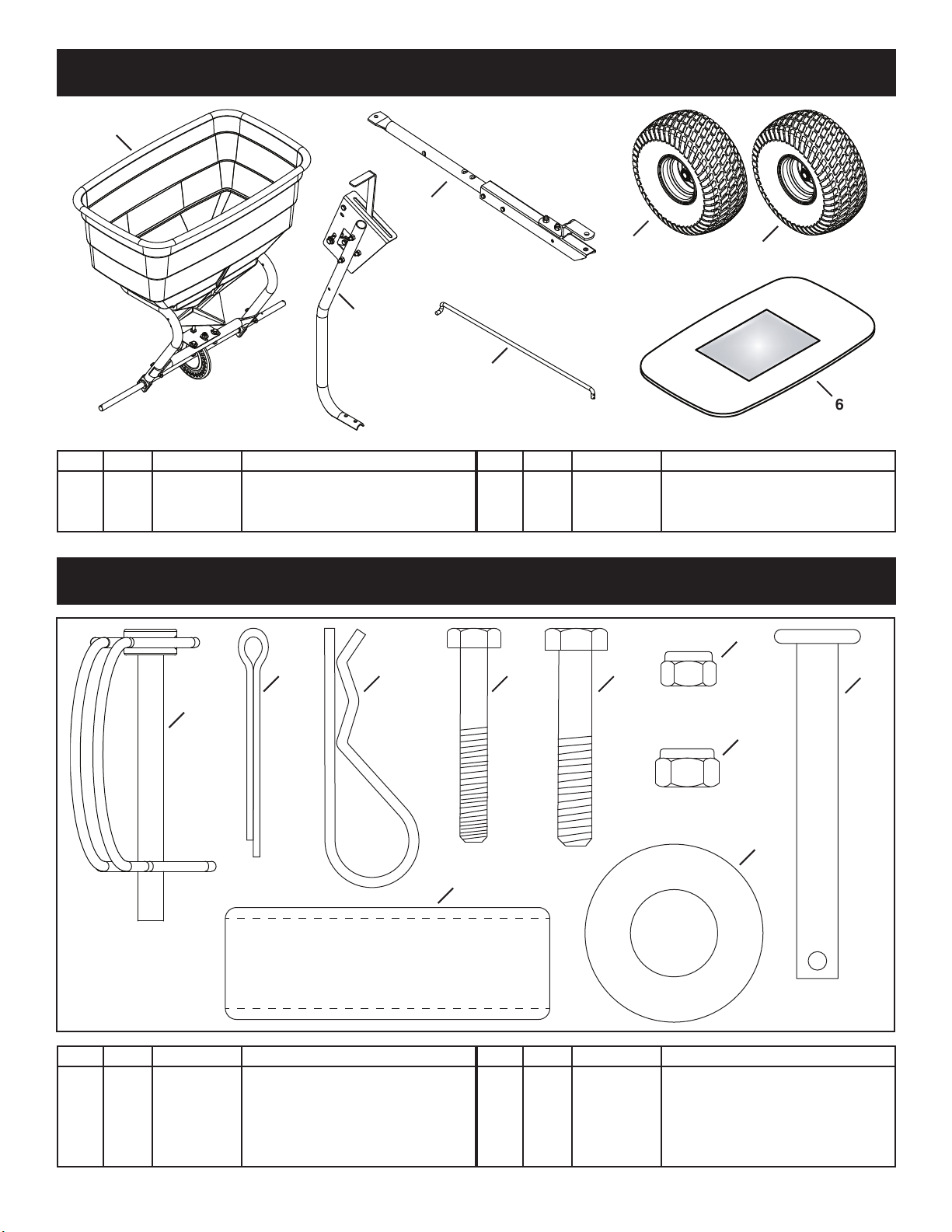
CARTON CONTENTS
12
1
2
3
REF QTY PART NO DESCRIPTION
1 1 — Hopper Assembly
2 1 — Hitch Tube Assembly
3 1 — Flow Control Tube Assembly
HARDWARE PACKAGE
8 9 10 11
4
5
REF QTY PART NO DESCRIPTION
4 2 42493 Wheel
5 1 41549 Flow Control Rod
6 1 40825 Hopper Cover
4
6
14
7
REF QTY PART NO DESCRIPTION
7 1 48515 Drive Pin w/ Bail
8 2 43093 Cotter Pin, 1/8" x 1-1/2"
9 1 43343 Hair Cotter Pin, 1/8"
10 2 1509-69 Hex Bolt, 1/4-20 x 1-3/4"
11 2 43084 Hex Bolt, 5/16-18 x 1/34"
13
15
REF QTY PART NO DESCRIPTION
12 2 47189 Nylock Nut, 1/4"
13 2 47810 Nylock Nut, 5/16"
14 1 47623 Hitch Pin
15 2 47683 Spacer
16 4 43009 Washer
3
16
Page 4
ASSEMBLY
1/4 NYLOCK
WHEEL
TOOLS REQUIRED FOR ASSEMBLY
(1) Pliers
(2) 7/16" Wrenches
(2) 1/2" Wrenches
(2) 9/16" Wrenches
REMOVAL OF PARTS FROM CARTON
Remove all parts and hardware packages from the
carton. Lay out all parts and hardware and identify using
the illustrations on pages 3.
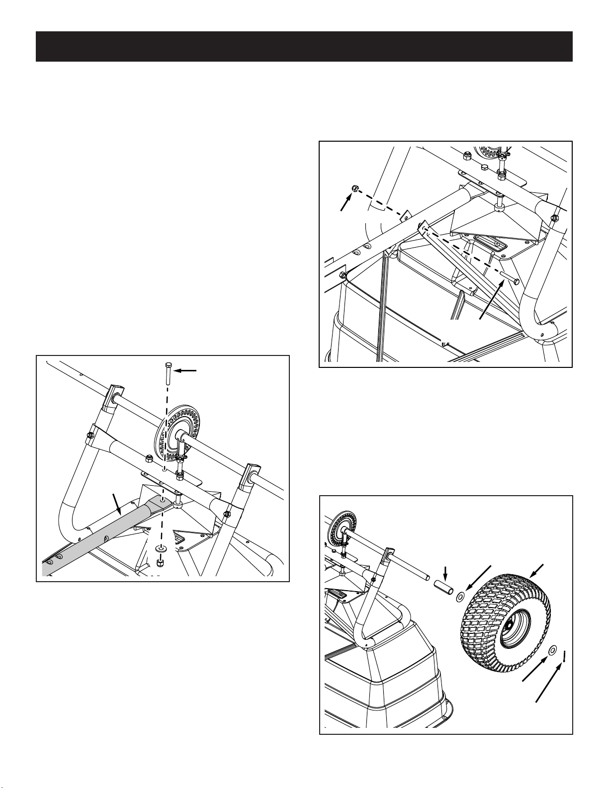
STEP 1: (SEE FIGURE 1)
• Turn the spreader upside down.
• Remove the lock nut from the middle bolt in the
crossover tube and shaft support plate. Leave the bolt
in place.
• Assemble the hitch tube onto the middle bolt and
secure it with the same lock nut you removed. DO
NOT TIGHTEN YET.
STEP 2: (SEE FIGURE 2)
• Assemble the OUTER hitch braces to the hitch tube
using a 1/4" x 1-3/4" hex bolt and a 1/4" nylock hex
nut. DO NOT TIGHTEN YET. Do not assemble the
inner hitch braces at this time.
NUT
1/4 x 1-3/4
HEX BOLT
FIGURE 1
HITCH
TUBE
MIDDLE BOLT
FIGURE 2
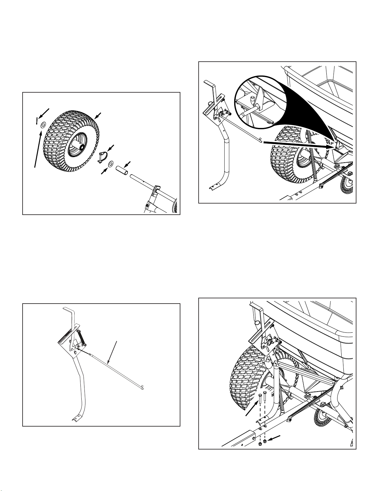
STEP 3: (SEE FIGURE 3)
• Assemble a spacer, a washer, a wheel (air valve
facing out) and another washer onto the end of the
axle that has only the small hole.
• Install a 1/8" x 1-1/2" cotter pin into hole in the axle.
SPACER
WASHER
FIGURE 3
4
WASHER
1/8 x 1-1/2
COTTER PIN
Page 5
1/8 x 1-1/2
STEP 4: (SEE FIGURE 4)
• Assemble a spacer, a washer, a wheel (air valve
facing out) and another washer onto the end of the
axle that has both the large and small holes.
• Install a 1/8" x 1-1/2" cotter pin into the small hole in
the end of the axle.
• Open the bail on the drive pin and install it through
the wheel and the large hole in the axle. Close the
bail to lock the pin in place.
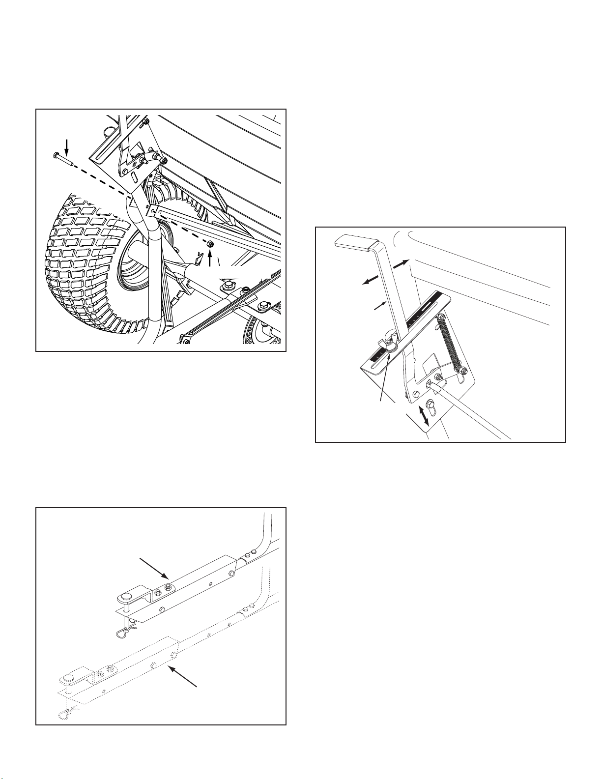
STEP 6: (SEE FIGURE 6)
• Turn the spreader upright on its wheels.
• Hook the double bent end of the ow control rod
through the hole in the slide gate bracket located near
the bottom of the hopper.
COTTER PIN
WHEEL
DRIVE PIN
SPACER
WASHER
WASHER
FIGURE 4
STEP 5: (SEE FIGURE 5)
• Insert the end of the ow control rod with only one
bend into the hole in the lever on the ow control tube
assembly.
FIGURE 6
STEP 7: (SEE FIGURE 7)
• Assemble the ow control mounting tube to the hitch
tube using two 5/16" x 1-3/4" hex bolts and 5/16"
nylock hex nuts. DO NOT TIGHTEN YET.
FIGURE 5
OFF
ON
1
2
3
4
5
6
7
8
9
10
CONTROL
ROD
5/16 x 1-3/4
HEX BOLT
5/16 NYLOCK NUT
FIGURE 7
5
FLOW
Page 6
1/4 x 1-3/4
STEP 8: (SEE FIGURE 8)
• Assemble the two INNER hitch braces to the ow
control mounting tube using a 1/4" x 1-3/4" hex bolt
and a 1/4" nylock hex nut. TIGHTEN.
• TIGHTEN all nuts and bolts assembled up to this
point. Do not collapse tubes when tightening.
HEX BOLT
1/4 NYLOCK NUT
FIGURE 8
STEP 10: (SEE FIGURE 10)
• Calibrate the ow setting. Follow the steps in order
below.
1. Push ow control arm to "OFF" position.
2. Slide ow control mounting bracket along tube
until closure plate in bottom of hopper just closes.
3. Snug the 5/16" nylock hex nuts just enough to
hold ow control mounting bracket in place.
4. Set adjustable stop at "5". Pull ow control arm
against stop. Verify that closure plate has opened
about half way.
5. If closure plate does not open half way, adjust
position of ow control mounting bracket until
closure plate will open about half way at "5"
and will still close when arm is locked in "OFF"
position. Tighten the 5/16" nylock hex nuts.
OFF
ON
OFF
ON
FLOW
CONTROL
ARM
8
9
10
0
1
2
3
4
5
6
7
STEP 9: (SEE FIGURE 9)
• For most vehicles, the hitch tube assembly should be
• Attach the spreader hitch to your vehicle hitch.
• Check for interference with the spreader directly
• If there is interference with the rear of the vehicle,
left in the default position.
behind and out to both sides of the vehicle. Lift the
spreader at each position to make sure there is no
interference with the spreader's ow control.
extend the hitch tube assembly.
DEFAULT POSITION
ADJUSTABLE
STOP
(SETTING "5")
FIGURE 10
FIGURE 9
EXTENDED
(IF INTERFERENCE)
6
Page 7
OPERATION
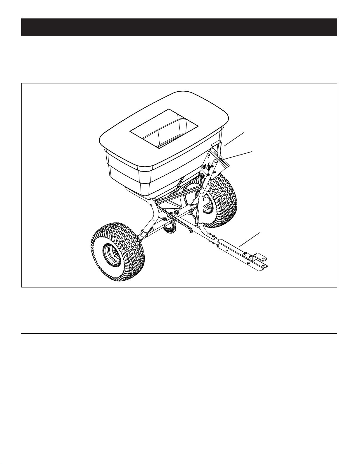
KNOW YOUR SPREADER
Read this owner's manual and safety rules before operating your spreader.
Compare the illustration below with your spreader to familiarize yourself with the various controls and their locations.
FLOW CONTROL ARM
ADJUSTABLE STOP
FLOW CONTROL ARM - Opens and closes the closure
plate in the bottom of the hopper.
ADJUSTABLE STOP - Limits how far the closure plate
opens.
HOW TO USE YOUR SPREADER
SETTING THE FLOW CONTROL
• Loosen the nylon wing nut, set the adjustable stop to
the desired ow rate setting and retighten the wing
nut. The higher the setting number, the wider the
opening in the bottom of the hopper.
• Refer to the application chart on this page and to the
instructions on the fertilizer bag to select the proper
ow rate setting.
• Pull the ow control arm against the adjustable stop
for the on position and toward the hopper for the off
position.
HITCH EXTENSION BRACKET
CLOSURE PLATE (not shown) - Slides to open or close
the opening in the bottom of the hopper.
HITCH EXTENSION BRACKET - Adjusts to allow more
clearance between the spreader and towing vehicle
FREE WHEELING FEATURE
• The spreader is equipped with a removable pin in the
left (drive) wheel.
• Remove the pin to disengage the drive wheel so that
the axle, gears, and spreader plate do not rotate.
• With the drive wheel disengaged, the spreader may
be towed at speeds up to 20 mph.
• If the drive wheel is engaged, do not exceed 6 mph.
7
Page 8
OPERATING TIPS
We do not recommend the use of any powdered lawn
chemicals due to the difficult in obtaining a satisfactory or
consistent broadcast pattern.
• Determine approximate square footage of area to be
covered and estimate amount of material required.
• Before lling the hopper, make sure the ow control
arm is in the off position and the closure plate is shut.
• Break up any lumpy fertilizer as you ll the hopper.
• Set the adjustable stop with the ow control arm still
in the off position. Refer to the application chart on
this page and to the instructions on the fertilizer bag
to select the proper ow rate setting.
• The application chart is calculated for light to heavy
application at a vehicle speed of 3 mph, or 100
ft. in 23 seconds. A variation in speed will require
an adjustment of the ow rate to maintain the
same coverage. The faster you drive, the wider the
broadcast width.
• Make sure the drive pin is installed in the axle before
starting the spreader.
• Always start the tractor in motion before opening
closure plate.
• Always shut the closure plate before turning or
stopping the tractor.
• If fertilizer is accidentally deposited too heavily in a
small area, soak the area thoroughly with a garden
hose or sprinkler to prevent burning of the lawn.
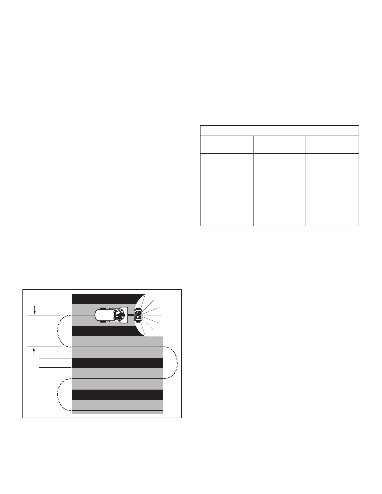
• To insure uniform coverage, make each pass so that
the broadcast pattern slightly overlaps the pattern
from the previous pass as shown in gure 13. The
approximate broadcast widths for different materials
are shown in the application chart on this page.
• When broadcasting weed control fertilizers, make
sure the broadcast pattern does not hit evergreen
trees, owers, or shrubs.
• Heavy moisture conditions may require a cover over
the hopper to keep contents dry. The vinyl cover acts
as a wind and moisture shield, but should not be
used as a rain cover.
IMPORTANT: Application rates shown in the chart are
affected by humidity and by the moisture content of
the material (granular and pellet). Some minor setting
adjustments may be necessary to compensate for this
condition.
APPLICATION CHART
TYPE OF
MATERIAL
FERTILIZER
Powder 3 - 5 3' - 4'
Granular 3 - 5 8' - 10'
Pelleted 3 - 5 10' - 12'
Organic 6 - 8 6' - 8'
GRASS SEED
Fine 3 - 4 6' - 7'
Coarse 4 - 5 8' - 9'
ICE MELTER 6 - 8 10' - 12'
OPERATING SPEED - 3 MPH (100 ft. in 23 seconds)
FLOW SETTING SPREAD WIDTH
REFER
TO
CHARTS
OVERLAP
FIGURE 13
8
Page 9
MAINTENANCE
(annually)
TROUBLESHOOTING
CHECK FOR LOOSE FASTENERS
• Before each use make a thorough visual check of
the spreader for any bolts and nuts which may have
loosened. Retighten any loose bolts and nuts.
CHECK FOR WORN OF DAMAGED PARTS
• Check for worn or damaged parts before each use.
Repair or replace parts if necessary.
CHECK TIRE INFLATION
• Check if tires are adequately inated before each use.
CAUTION: DO NOT inate tires beyond the
maximum recommend pressure printed on
side of tire.
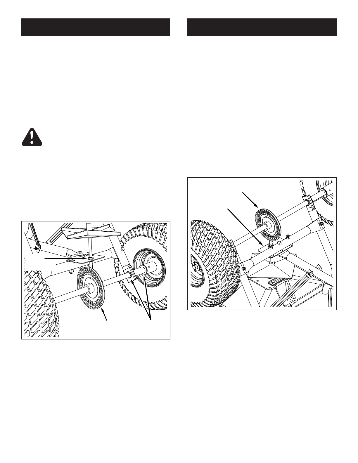
LUBRICATE (See gure 11)
• Lightly apply automotive grease as needed to the
sprocket and gear.
• Oil the nylon bushings on the vertical sprocket shaft
and on the axle at least once a year, or more often as
needed.
• Oil right hand (idler) wheel bearing at least once a
year or more often as needed.
LOCKED UP SPREADER
• Turn the spreader over so that the wheels are off the
ground.
• Loosen all three nuts on the shaft support plate so
that the bolts can be turned easily with a wrench but
cannot be turned by hand.
• Spin the drive wheel and note how freely it spins and
how much noise the gear makes.
• To free up wheel and gear, tap gently on the front or
rear edge of the shaft support plate to move it slightly
forward or backward. You can also tap at the corners
of the plate to angle it slightly.
• Spin the drive wheel after each adjustment to see if it
spins more freely and if the gear noise is reduced.
• Continue making slight adjustments until you nd the
position where the drive wheel spins most freely and
the gear makes the least noise.
• Secure the shaft support plate in this position by
retightening all three nuts that you loosened.
GEAR
SHAFT
SUPPORT
PLATE
OIL
(annually)
GREASE
(when needed)
FIGURE 11
OIL
STORAGE
• Rinse inside of hopper and exterior of spreader and
dry off before storing.
• Store in a clean, dry area.
FIGURE 12
9
Page 10
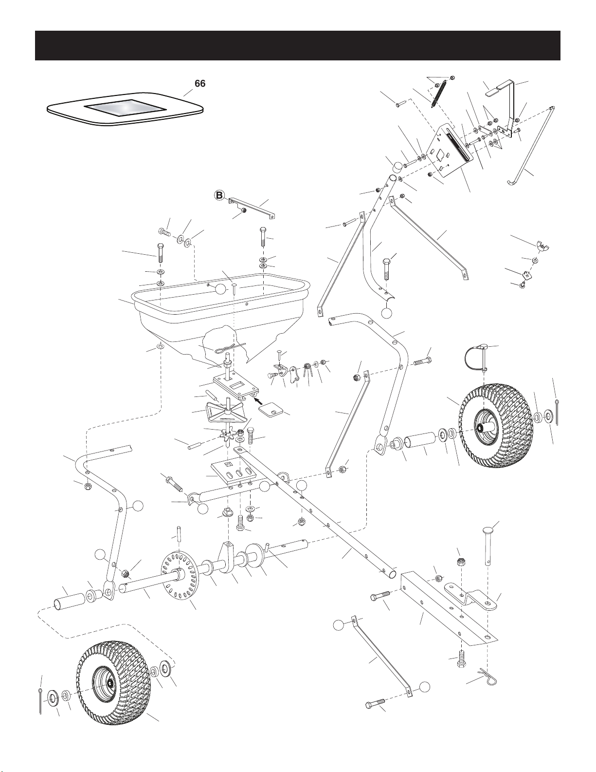
REPAIR PARTS ILLUSTRATION
47
9
4
24
39
44
9
58
34
39
53
39
40
58
40
66
39
58
64
45
54
39
51
8
13
39
54
OFF
ON
1
2
3
4
5
6
7
8
9
10
58
11
9
65
13
54
42
9
9
37
53
40
2
39
35
63
11
B
35
61
41
60
1
A
4
23
24
37
9
15
62
49
67
50
50
67
55
7
17
40
31
29
3
59
26
7
28
27
25
9
12
10
D
36
E
29
52
C
32
7
58
33
5
13
30
46
9
9
40
57
6
35
9
A
19
E
13
14
23
21
20
21
19
22
18
43
D
53
16
49
50
67
67
15
50
10
35
37
48
C
56
Page 11
REPAIR PARTS LIST
REF QTY PART NO DESCRIPTION
1 1 44480 Hopper
2 4 41157 Rivet, Stainless
3 1 65129 Guide Closure Assembly
4 1 44462 Frame Tube
5 1 23753 Slide Gate Angle Bracket
6 1 23758 Slide Gate Bracket
7 5 HA21362 Nylock Hex Nut, 3/8-16
8 1 24857 Flow Control Link
9 19 47189 Nylock Hex Nut, 1/4-20
10 1 43808 Crossover Tube
11 4 43084 Hex Bolt, 5/16-18 x 1-3/4"
12 2 44180 Hex Bolt, 5/16-18 x 2"
13 8 47810 Nylock Hex Nut, 5/16-18
14 1 48864 Hitch Tube
15 2 48511G Wheel
16 1 25080 Hitch Extension Bracket
17 1 23014 Hitch Bracket
18 1 24914 Axle Shaft
19 2 43851 Spring Pin, 3/16 x 3-1/4"
20 1 43871 Axle Shaft Bushing
21 5 44008 Flat Washer, .78"
22 1 1540-162 Flat Washer, 1/2"
23 2 47615 Flange Bearing
24 2 47683 Spacer Tube
25 1 25305 Sprocket Shaft
26 1 04367 Spreader Plate
27 1 43850 Spring Pin, 1/8 x 5/8"
28 1 44468 6 Tooth Sprocket
29 2 44285 Delrin Bushing
30 2 C-9M5732 Rivet
31 1 48934 Hairpin Agitator
32 3 43070 Flat Washer, 3/8"
33 2 43054 Hex Bolt, 3/8-16 x 2"
34 1 41549 Flow Control Rod
REF QTY PART NO DESCRIPTION
35 4 23525 Hitch Brace
36 1 23762 Shaft Support Plate
37 4 1509-69 Hex Bolt, 1/4-20 x 1-3/4"
38 1 42505 Plastic Grate
39 14 1543-69 Nylon Washer
40 15 43088 Flat Washer, 1/4"
41 1 27177 Adjustable Stop
42 1 24915 Flow Control Mount Bracket
43 1 62474 Gear Assembly
44 1 24917 Flow Control Arm
45 1 43000 Spring
46 1 23533 Closure Plate
47 1 43848 Flow Control Arm Grip
48 2 43001 Hex Bolt, 3/8-16 x 1"
49 2 43093 Cotter Pin, 1/8" x 1-1/2"
50 4 43009 Flat Washer, 3/4"
51 1 43085 Hex Bolt, 5/16-18 x 1-1/2"
52 1 HA180132 Hex Bolt, 3/8-16 x 2-1/4"
53 8 46699 Hex Bolt, 1/4-20 x 2"
54 5 43081 Washer, 5/16"
55 1 47623 Hitch Pin
56 1 43343 Hair Cotter Pin, 1/8"
57 1 44566 Torsion Spring
58 6 43661 Hex Bolt, 1/4-20 x 1"
59 1 46055 Spring Pin, 1/8 x 1"
60 1 44950 Carriage Bolt, 1/4-20 x 3/4"
61 1 47141 Nylon Wing Nut
62 1 48515 Drive Pin w/Bail, 1/4 x 2"
63 1 48514 Flow Control Mounting Tube
64 1 44481 Vinyl Cap
65 1 23697 Hopper Strap
66 1 40825 Vinyl Cover
67 4 43631 Ball Bearing
1 42523 Owners Manual
11
Page 12

ORDERING REPLACEMENT PARTS
To order replacement parts, call Sears Parts Direct 1-800-252-1698
12
 Loading...