

Page 1
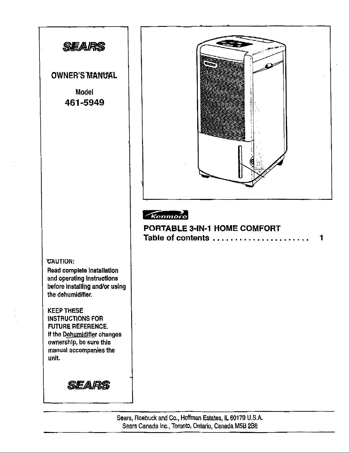
OWNER'SWtANUAL
Model
461-5949
PORTABLE 3-1N-1 HOME COMFORT
Table of contents ......................
"CAUTION:
Read complete installation
and operating instructions
beforeinstalling and/or using
the dehumidifier.
KEEPTHESE
INSTRUCTIONS FOR
FUTUREREFERENCE.
Ifthe D_i_er changes
ownership,be sure this
manual accompaniesthe
unit.
Sears,RoebuckandCo,, HoffmanEstates,IL60179 U.S.A.
SearsCanadaInc.,Toronto,Ontario,CanadaMSB2B8
Page 2
U_/3U/Y_ UU:43 *_'_47 Z_6 0147 SEARS _019
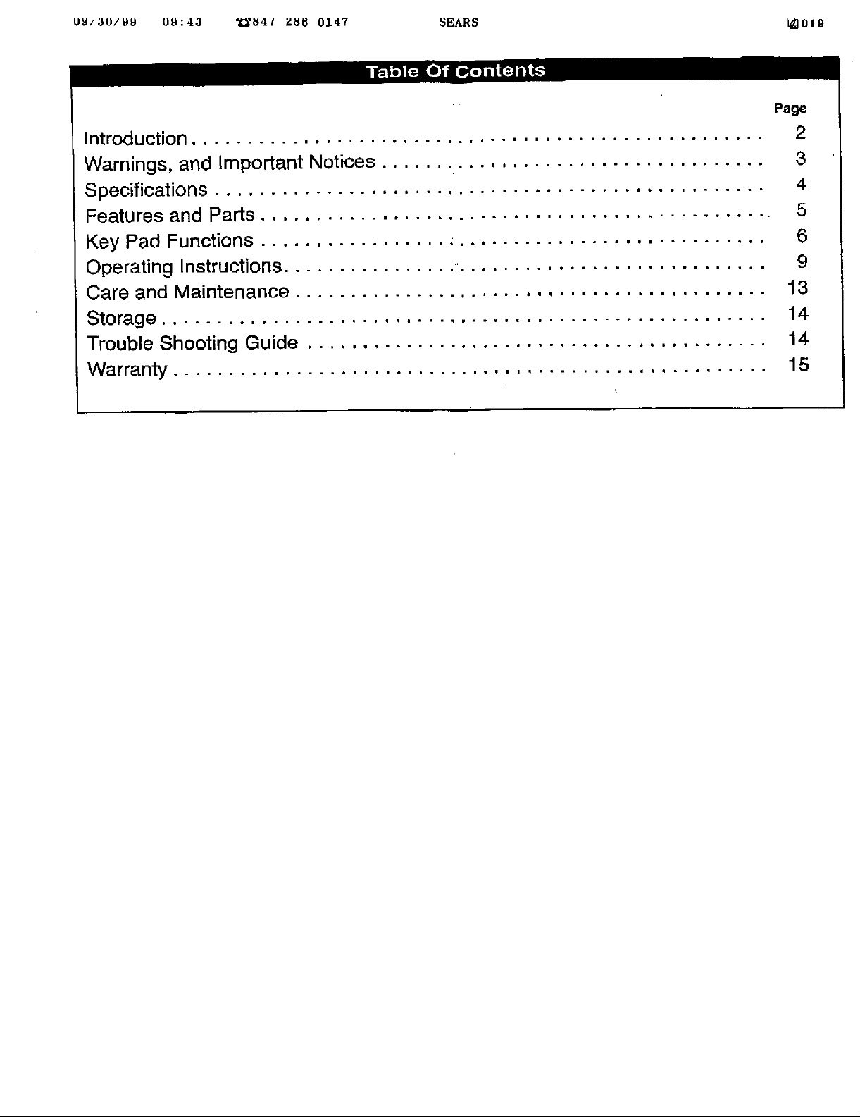
Page
Introduction ....................................................
Warnings, and Important Notices
Specifications ...............
Features and Parts ...........
Key Pad Functions ...........
Operating Instructions .........
Care and Maintenance ........
Storage ....................
i.pn.oo,o,lw, .... _.. .... wwm,_.oo°.
.,.o=w,.,.==o,.w.=.,o.almJmwoo..o-
,oo.b,=.=o,_mwm.w.oo.,_° .... o,,,D..
q...,_ooP, ..... lloo=ooww ....... ,iw
..... w'_i,ll .... meoo.omhmliwo=.,..ol
o.ooo,w,,o.=ilq,o,.,,mlmmll°.,_m=.
qm,° qm.ouolo_,o...-.oo.o.._m°o,o
Trouble Shooting Guide ..........................................
Warranty ......................................................
2
3
4
5
6
9
13
14
14
15
Page 3
I
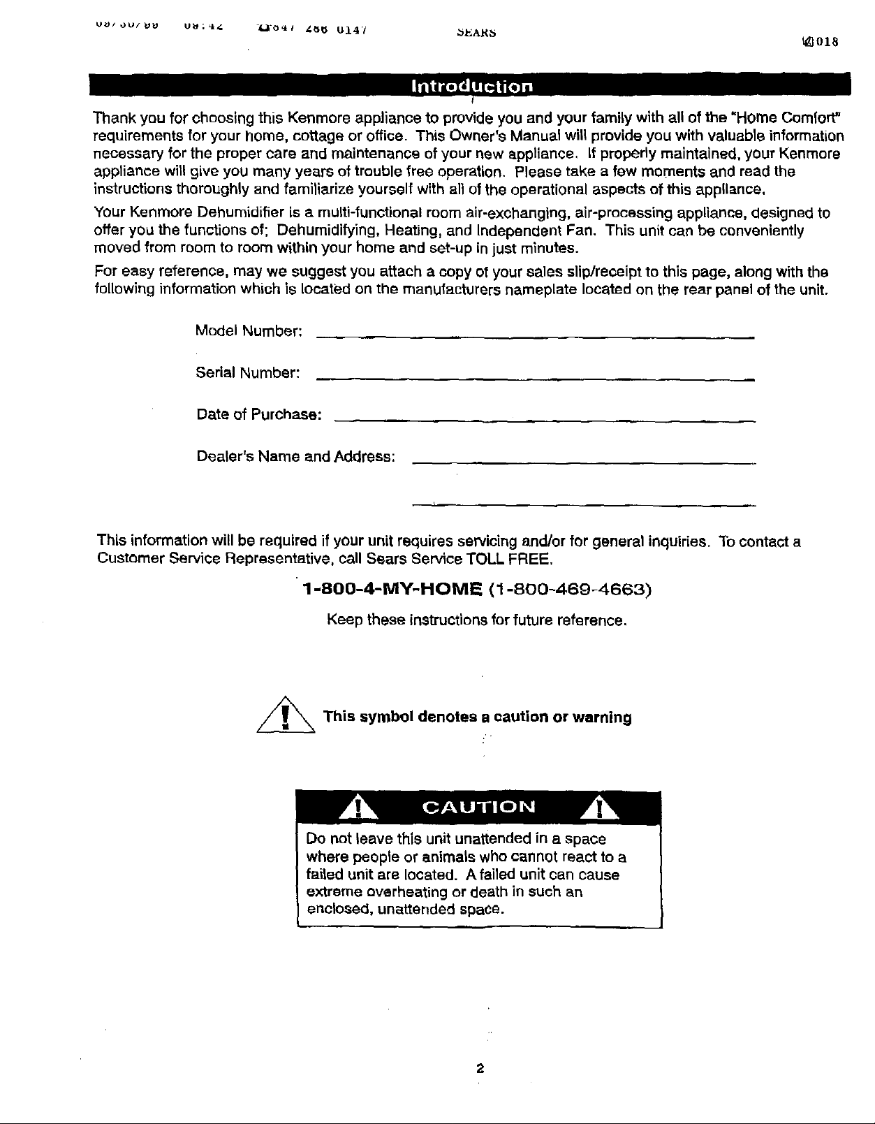
Thank you for choosing this Kenmore appliance to provide you and your family with all of the "Home Comfort"
requirements for your home, cottage or office. This Owner's Manual will provide you with valuable information
necessary for the proper care and maintenance of your new appliance, If properly maintained, your Kenmore
appliance will give you many years of trouble free operation. Please take a few moments and read the
instructions thoroughly and familiarize yourself wlth all of the operational aspects of this appliance.
Your Kenmore Dehumidifier is a multi-functional room air-exchanging, air-processing appliance, designed to
offer you the functions of; Dehumidifying, Heating, and Independent Fan. This unit can be conveniently
moved from room to room within your home and set-up in just mlnu'_s.
For easy reference, may we suggest you attach a copy of your sales slip/receipt to this page, along with the
following information which is located on the manufacturers nameplate located on the rear panel of the unit.
Model Number:
Serial Number:
Date of Purchase:
Dealer's Name and Address:
This information will be required if your unit requires servicing and/or for general inquiries. To contact a
Customer Service Representative, call Sears Service TOLL FREE.
1-800-4-MY-HOME (1-800-469-4663)
Keep these instructions for future reference.
_This symbol denotes a caution or warning
Do not leave this unit unattended in a space
where people or animals who cannot react to a
failed unit are located. A failed unit can cause
extreme overheating or death in such an
enclosed, unattended space.
2
Page 4
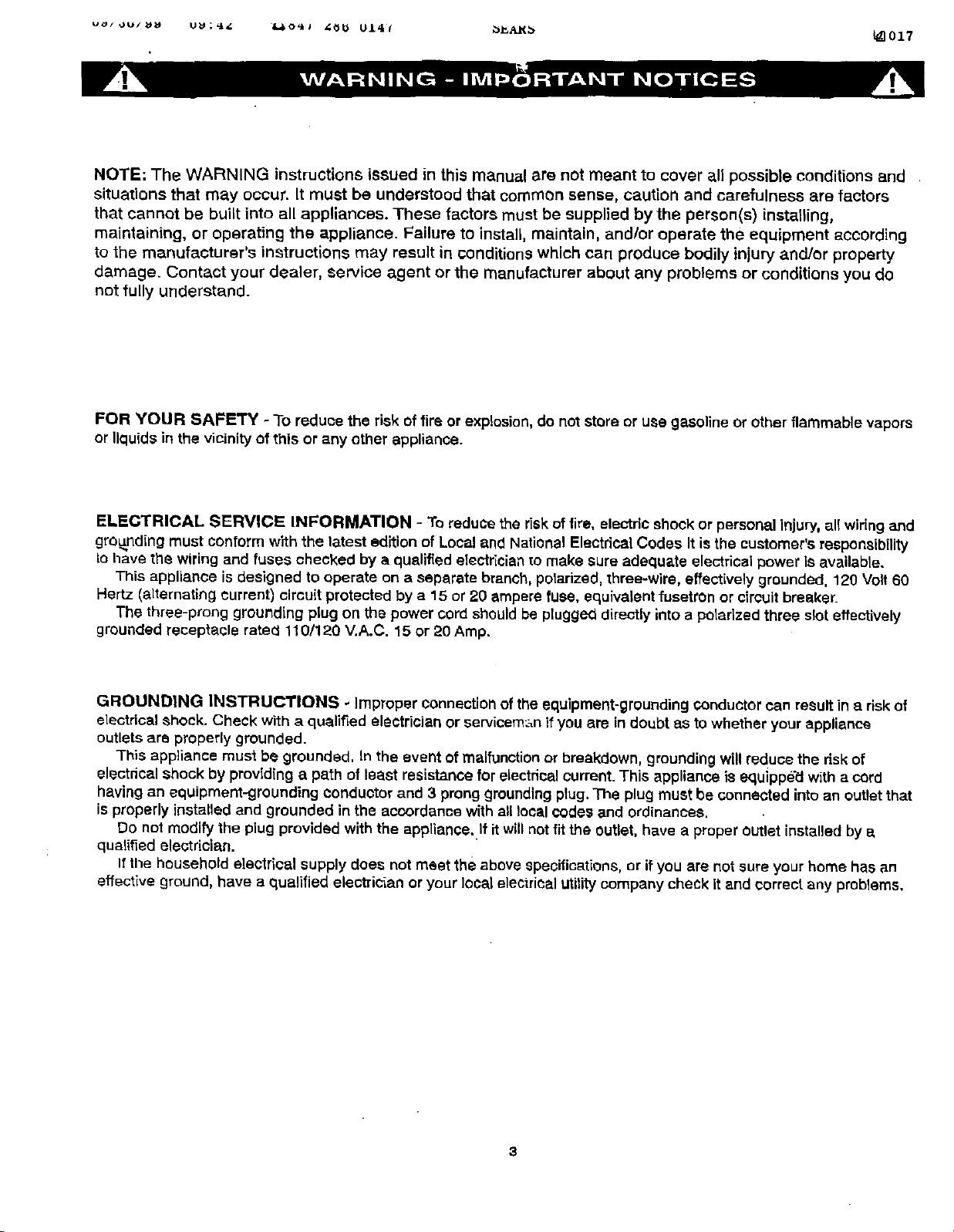
NOTE; The WARNING instructions issued in this manual 8re not meant to cover a.ll possible conditions and
situations that may occur. It must be understood that common sense, caution and carefulness are factors
that cannot be built into all appliances. These factors must be supplied by the person(s) installing0
maintaining, or operating the appliance. Failure to install, maintain, and!or operate the equipment according
to the manufacturer's instructions may result in conditions which can produce bodily injury and/or property
damage. Contact your dealer, service agent or the manufacturer about any problems or conditions you do
not fully understand.
FOR YOUR SAFF'I"Y - To reduce the risk of fire or explosion, do not store or use gasoline or other flammable vapors
or Ilqu(ds in the vicinity of this or any other appliance.
ELECTRICAL SERVICE INFORMATION - To reduce the dsk of tire, electdc shock or personal injury, all wiling and
grounding must conform with the latest edition of Local and National Electrical Codes It is the customer's responsibility
Lohave the wiring and fuses checked by a qualified electrician to make sure adequate electrical power Is available.
This appliance is designed to operate on a separate branch, polarized, three-wire, effectively grounded, 120 Volt 60
Hertz (alternating current) circuit protected by a 15 or 20 ampere fuse, equivalent fusetron or circuit breaker.
The three-prong grounding plug on the power cord should be p]uggecidirectly into a polarized three slot effectively
grounded receptacle rated t 10/120 V.A.C. 15 or 20 Amp.
GROUNDING INSTRUCTIONS _ Improper Connection of the equipment-grounding conductor can result in a risk of
electdcal shock. Check with a qualified electriciar_ or ser'Jicem:_n if you are in doubt as to whether your appliance
outlets are properly grounded.
This appliance must be grounded. In the event of malfunction or breakdown, grounding will reduce the risk of
electrical shock by providing a path of least resistance for electrical current. This appliance is equippe_dwith a c_rd
having an equipment-grounding conductor and 3 prong grounding plug. The plug must be connected into an outlet that
is properly installed and grounded inthe acoordance with all localcodes and ordinances.
Do not modify the plug provided with the appliance. If it willnot fit the outlet, have a proper outlet installed by a
qualified electrician.
If the household electrical supply does not meet the above specifications, or ifyou are not sure your home has an
effective ground, have a qualified electrician or your local electrical utilitycompany check It and correct any problems.
3
Page 5
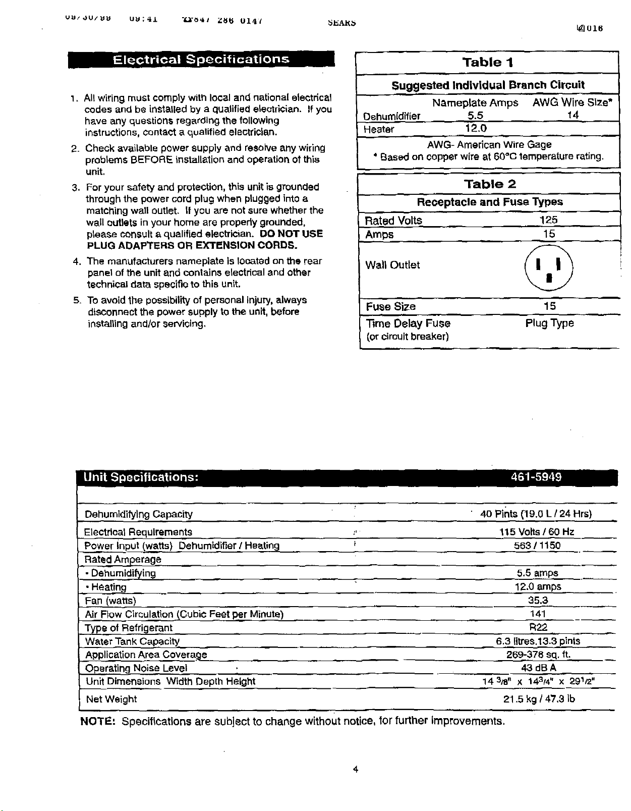
1. Allwiring must comply with local and national electrical
codes and be installed by a quatified electrician. If you
have any questions regarding the following
instructions, contact a qualified electrician.
2. Check available power supply and resolve any wiring
probtems BEFORE installation and operation of this
unit.
3. For your safety and protection, this unit is grounded
through the power cord plug when plugged into a
matching wall outtet. If you are not sure whether the
well cutters in your home are propedy grounded,
please consult a qualified electrician, DO NOT USE
PLUG ADAPTERS OR EXTENSION CORD_.
4. The manufacturers nameplate is located on the rear
panel of the unit and contains electrical and other
technical data specific to this unit.
5. To avoid the possibility of personal injury, always
diSConnect the power supply to the unit, before
installing and/or servicing.
Table I
Suggested Individual Branch Circuit
Nameplate Amps AWG Wire Size*
Dehumidifier 5.5 14
Heater 12,0
AWG- American Wire Gage
° Based on copper wire at 6O°C temperature rating.
Tab
Receptacle and Fuse Types
Rated' Volts _ 125
Amps 15
Wall Outlet
Fuse Size 15
Time Delay Fuse Plug Type
(or circuit breaker)
Dehumidifying Capacity
Etectdeal Requirements
Power input !wafts) Dehumidifier / Heating
Rated Amperage
• Dehumidi_ing
• Heatin9
i
Fan (wa e)
Air Flow Circulation [Cubic Feet per Minute)
Type of Refrigerant
Water Tank Capacity
Application Area CovereSe
Operating Noise Level
Unit Dimensions Width Depth Height
Net Weight 21.5 kg / 47,3 Ib
NOTE'. Specifications are subject to change without notice, tor further improvements.
....... ,, ,,
4
40 Pints (-19.0L/24 Hrs)
115 Volts 160 Hz
563 / 1150
5.5 emps
12.0 amps.
35.3
141
R22
6.3 litres.13.3 pints
269-378 sq. ft.
43dBA
14 3/8, X 143t4 " X 291/2"
Page 6
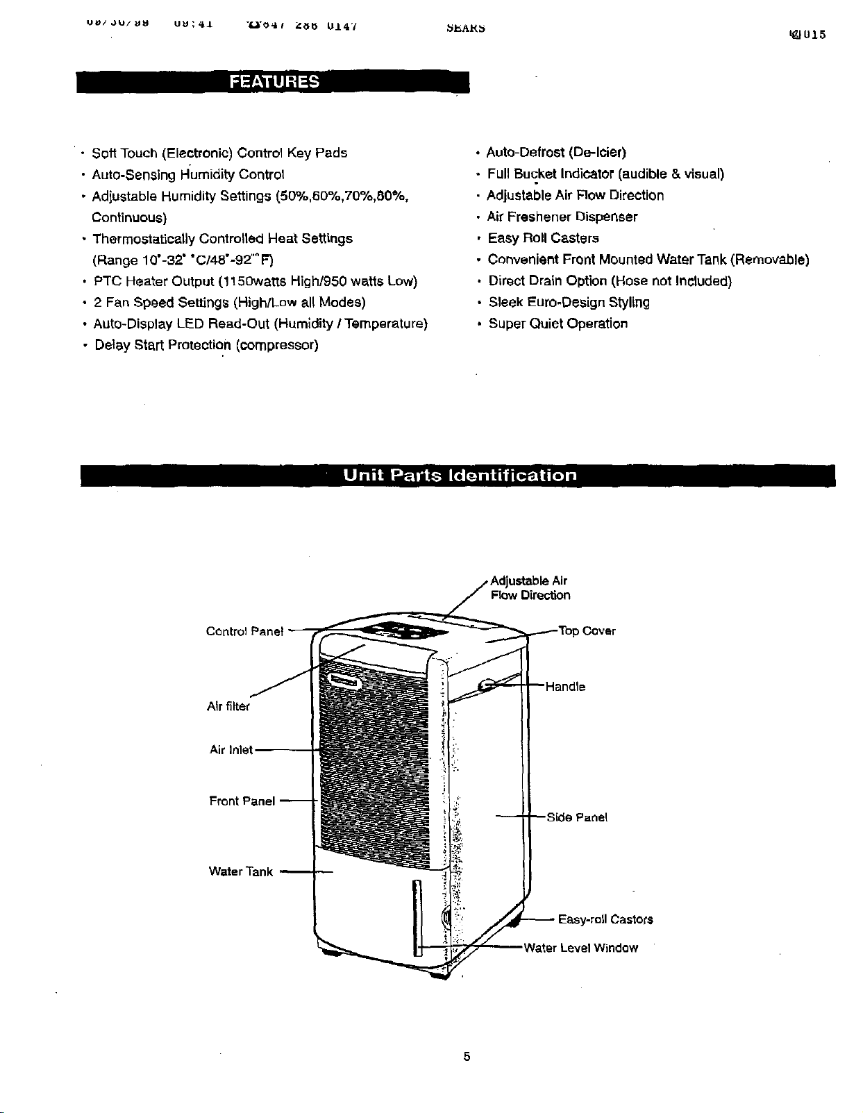
• Soft Touch (Electronic) Control Key Pads
• Auto-Sensing Humidity Control
• Adjustable Humidity Settings (50%,60%,70%,80%,
Continuous)
• Thermostatically Controlled Heat Settings
(Range 10" -32" "C/48"-92"" F)
• PTC Heater Output (1150watts High/950 watts Low)
• 2 Fan Speed Settings (High/Low all Modes)
• Auto-Display LED Read-Out (Humidity/Temperature)
• Delay Start Protection (compressor)
• Auto-Defrost (De-Icier)
Full Bucket Indicator (audible & visual)
Adjustable Air Flow Direction
Air Freshener Dispenser
Easy Roll Casters
Convenient Front Mounted Water Tank (Removable)
Direct Drain Option (Hose not Included)
Sleek Euro-Design Styling
Super Quiet Operation
Air filter
Air Inlet,
Flow Direction
) Cover
Panel
ts
Window
Page 7

DRY: is abbreviated for "DI=HUMIDIP{ "
FqH: is abbreviated for "Relative Humidity"
"C: is abbreviated for the "Celsius" scale
"F: is abbreviated for the "Farenheight mscale
On/Off Fleshing Light
When the unit is first connected to an electrical (outlet)
power s_Jpply,the (green) pilot light located above the
"ON/OFF" keypad flashes continuously. The flashing
light indicates a "power interruption"occurred and will stop
only after the unit is switched on using the on/off keypad.
This condition occurs each time the unit is disconnected
(unplugged) and re-connected, and/or inthe event of a
power fadure.
.... 1_014
i_ --FAN
Factory Default Setting
Each time the unit is switched on after being
disconnected/re-connected and/or in the event of a power
failure, the electronic clrouit board automatically defaults
to the following factory setting,
Mode: Dry
RH: 60%
Fan Speed: High
"C: Scale
All previous settings are automatically erased/cancelled.
Therefore, ff your program setting was different than the
above, you will have to re-set the original program. When
the unit is "manually" switched "on/off _ (using the onleff
keypad) the unit will default to the Last program setting
used.
Page 8

(Dry,Heat,Fan)ModeLights: WaterFull Flashing Light/Audible Alarm:
Upon selecting e mode, a solid green light (window)
illuminates adjacent to the modet selected, Under the
"Dry = and "Heat" mode (only) this light also serves to
identify the operational status of the selected
(compressor/heater) program. (see below)
Ory_
A "solid" green llght indicates the compressor cycled "on"
and is operalJonal.
A "flashlng" green light indicates the compressor cycled
"off" and is non-operal_onel. The fan motor will continue
to operate (fleahing green light condition) even after the
compressor has eycled off. This is a normal condition.
Heat:
A"solid" green light indicates the heating element cycled
"on" and is operational. A"flaahlng 't green light
indicates the heating element cycled "off'. Both heater
and fan motor will not be operationat during this (flashing
greeq, light) condition.
Fan Mode:
Since there are no controlled settings/options in this
mode, ether than fan speed, (high/low) the solid green
light remains on at all times until the mode is changed
and/or the unit is switched off.
Dry Mode:
The water full lightflashes continuously and an audible
alarm will sound (8 beeps) to notify you when the water
tank is full end/or is notpropedy positioned inside the
cabinet, The dehumidifier will cease (stop) ell operation
automatically, during this condition, (This is e safety
feature.)
Heat & Fan Mode;
The water full light and audible alarm operate in the same
basic manner described in the "DRY" mode (above).
However, the significant difference being both the "Heater
& Fan" will continue to operate under a (full water tank)
flashing light condition. Since no dehumiditylng occurs
during these modes. However, switching beck to the
"DRY_ mode will immediately atop any dehumidifying
operation.
Dry Level Mode Lights'
(Continuous, 5o%, 60%, 70%, 80%):
A solid green light (window) illuminates adjacent to the
RH% level selected.
Fan Speed Selection:
Two fan speeds ere available in ell operating modes,
"High/Low" identified by a solid green light (window)
adjacent to the mode selected,
7
Page 9

(_ Depending on the mode selected, this keypad (_ Del_endingon the mode selected, this keypad
performs the following function, performs the following function:
DRY Mode:
Allows you to select a Relative Humidity setting
(Continuous, 50%, 60%, 70%, 60%). Performs the
same basic function as the "DRY" key pad-
HEAT:
Allows you to adjust/Increase (upward) required
temperature settings.
FAN: _AN:
No Function klo Function
DRY:
Allows you to view exieting environment conditions.
ie: "temperature" ("Cr F)
ie: "relative humidity" (%)
HEAT:
Allows you to adjust/decrease (downward),
required t_mperature settings.
-= CONTINUOUS m DRY == HIGH •
-- 50%RH --, HEAT -- LOW W_--- -
-- 6O%RH == FAN. "_
-= 70%RH _ _ F/_ j
m 80%RH
_ -- RH
Page 10

DEHUMIDIFYING OPERATING INSTRUCTIONS
Dehumidifying:
Before Starting This Unit
Select a suitable location, making sure you have
easy access to an electrical outlet,
Dehumidifying is a means of removing moisture from the
air. A dehumidifier will help to protect your home and
vetued possessions from damage caused by moisture
(swelting) during high humidity conditions. Essentially a
dehumidifier removes moisture from the air, as moist air
passes over a dehumidi_ing coit (evaporator).
Moisture is condensed onto the evaporator, drained and
collected inside an infernal water tank. The exhausted air
being returned into the room environment is elevated
several degrees causing the surrounding air temperature
to increase (slightly). This proceSS also contributes to
lowering the relative humidity of surrounding air.
Loostion:
To obtain maximum operating efficiency from your
dehumidifier, the recommended (room ambient) operating
temperature should be between 15.5°C/60"F - 32'C/90"F.
it is important to remember the efficiency of a dehumidifier
will be affectedlinfluenced by the rate at which new
moisture is allowed to infiltrate the same space/area. To
maintain efficiency, the dehumidifier must be operated in
an enclosed area. Keep all doors and windows closed. '
The dehumidifier mode provides a feature thai will allow
you the option of reading current room ambient
temperatures in "Celsius" or "Faranheight"_
Follow these steps:
Oepress the MODE keypad. Each depression of
the key pad will alternate through each of the
optional modes. (DRY, HEAT, FAN). When the
window adjacent to the "DRY" mode illuminates,
the selection is complete.
Depress the _> keypad, allowing you to alternate
between the *C/F RH settings adjacent to the LED
display.
3.
When the window adjacent to the "C illuminates,
the LED will display the existing ambient room
temperatures in "Celsius".
4. When the window adjacent to the "F iltuminates,
the LED will display the existing ambient room
temperatures in "Ferenheight".
5. When the window &djacsnt to the RH illuminates,
the LED will display existing room humidity
conditions as a "percentage" (%) value.
Select a suitable location making sure there are no
obstructions restricting aiHIow st the front and back of the
unit•
Installation:
1, Connect the power cord into a propedy grounded
polarized 110/115 voltNC receptacle. (For your
safety, please refer to grounding instrustions page 3):
2. Make sure the water tank is properly installed inside
the cabinet, lithe (red) "water full" light starts
flashing when the Unitis plugged in, the water tank is
not properly installed.
3. When the unit is fir_ connected to a power supply, the
(green) pilot light located directly above the "On/Of_
keypad will flash continuously (this is normal). The
flashing light indicates the circuit board encountered a
power failure/interruption (from being unplugged). The
flashing light condition will cease immediately when
the unit is switched on using the On/Off key pad and
the unit will automatically default to the factory seffing
previously described. The default setting cannot be re-
programmed.
9
Page 11

uu/au/vu uu;_o "/,3"o_ 4_b UI41 3_AH_ L_]01O
2. Depress the (_) keypad, allowing you to alternate
Selecting a Relative Humidity Setting:
between the "CPF RH settings adjacent to the
LED display
All of the settings on your dehumidifier are electronically
controlled.
3, When the window adjacent to the "C illuminates,
the LED will display temperatures in "Celsius".
50% maintains a 50% Relative Humidity level
60% maintains a 60% Relative Humidity level
70% maintains a 70% Relative Humidity level
80% maintains a 80% Relative Humidity level
"CONTINUOUS" will dehumidify "non-stop"
4. When the window adjacent to the "F illuminates,
the LED will display temperatures in
"Farenheight". The illuminated RH window
automatically defaults to the "C (Celsius) scale
To select a Relative Humidity setting,
(Continuous, 50% 60%, 70%, B0%)
1. Depress the "DRY" keypad until the required setting is
selected. Each depression of the keypad will change
the relative humidity setting, identified by the
illuminated window adjacent to your selection made. (If
existing relative humidity conditions in your room
register "lower" than the relative humidity level
HEAT MODE:
To select nHeat", depress the "mode" key pad. Each
depression of the key pad will alternate through each of
the optiona! modes. (DRY, HEAT, FAN) When the window
adjacent to the "Heat" mode illuminates, the selection Is
complete.
selected, No dehumidifying will take place (fleshing
..green window), The fan will operate but the
compressor wilt remain in an oft cycle, until the relative
humidity level is lowered accordingly (below RH level
of room),
Temperature;
To select]adjust "temperature" depress either of the
/ _) key pads.
The _ keypad increases temperature settings. (as
outlined below)
The _ keypad decreases temperature settings. (as
outlined below)
Selecting a Fan Speed Mode:
(Celsius scala 1" increments) Adjustable temperature
1. To select a fan speed, each depression of the
"Fan" keypad will alternate between the "High" &
"Low" fan speed settings, identified by the
range 10"0-32"C)
(Fatenheight scala 2" increments) Adjustable temperature
range 4B"F-92" F)
illuminated window adjacent to your selection.
The temperature appearing in the LED display ia the
temperature at which heater will cycle.
Both heater and fan will stop, when the ambient room
Heat mode:
temperature reaches the set temperature, displayed in th*
LED window
The Heat mode provides a featUre that will allow you the
option to setting temperatures in either "Celsius" or
"Farenheight".
Fan Speed,
Each depression of the "Fan" keypad will alternate
between the "High" & "Low" fan speed s_ttlngs,
NOTE: This must be accomplished before you pro-select
the HEAT mode option
identified by the illuminated window adjacent to your
selection.
It is not possible to aCcess existing ambient room
conditions during HEAT mode,
• High Fan: will produce 1150 watts of Heating output
• Low Fan will produce 950 watts of Heating output
Follow these steps:
t, Depress the MODE keypad to select either DR'i
or FAN, Identified by the illuminated window
adjacent to the selection,
10
Page 12

u_/au/uu uu:o_ *_'_41 Z_U u147 SEARS _009
Fan Mode;
Fen Mode helps to purify end circulate indoor air.
The Fen Mode provides a feature that will allow you the
option of reading current room ambient temperatures in
"Celsius" or "Farenhsight"_
Followthese steps.
1. Depress the MODE keypad, Each depression of the
key pad will alternate through each of the optional
modes• (DRY, HEAT, FAN). When the window
adjacent to the "FAN" mode illuminates the selection is
complete.
2. Depress the _ keypad, allowing you to alternate .
between the "C/F settings adjacent to the LED
display.
3. When the window adjacent to the "C illuminates, the
LED the will display existing ambient room
temperatures in "Celsius",
*.m
4 When the window adjacent to the °F illuminates, the
LED will display existing ambient room temperatures in
"Farenheight".
Adjustable Air Flow Direction:
The adjustable air flow discharge port is located onthe
top of the dehumidifier. (See Fig. I).
1. The word "PUSH" is stamped on each side of the air
discharge cover. Push these locations and the air
discharge port will rotate (open) approximately 85",
(See Fig.lA). It is recommended to keep the air
discharge port fully open at all times during operation
(ell modes).
2,
If the air discharge port is accidentally closed during
operation, itwill not damage the unit. The air
Circulationwill automatically discharge throu0h the rea_
of the unit. However, operating efficiency of the unit
may be compromised.
iii
Fig.1
5, When the window adjacent to the RH illuminates, the
LED will display existing room humidity conditions as a
"percentage" (%) value.
Mode:
To select "Fan" depress the "mode" key pad. I=ach
depression of the key pad will alternate through each of
the optional modes. (DRY, HEAT.FAN). When the window
adjacent to the "FAN" mode illuminates the selection is
complete,
Fen Speed
Each depression of the "Fan" keypad will alternate
between the "HIGH" & "LOW _ fan speed settings,
identified by the illuminated window adjacent to your
selection.
-- 7o,_,,q,1
•:_ i ,.' .,:_ _,.-
• • .• / ; ,:i•y ¸ "
•' ".'.. ,.. t••;
11
Page 13

u_/ou/us UU:_/ "_'_4t _8_ 0147 SEARS _008
Air Freshener Dispenser:
Your dehumidifier features an air freshener dispenser,
located next to the air flow discharge port. Fresheners
are not included with the unit. These items can be
purchased through your local grocery store.
Place the freshener (solid/liquid) inside the dispenser,
the aroma will be disbursed with the out-going air_
See Fig. 2
Removable Air Filter:
Your dehumidifier features a removable air rilter,
located on top (front section) of the unit. The filter will
help reducelminimize dust and dirt pa_eles in the
environment. Never operate the dehumidifier without the
air filter in place.
Check the filter regularly (every 2 weeks), if it becomes
blocked/dogged, incoming airflow will be restricted
reducing operating efficiency, More frequent cleaning
Fig. 2
may be necessary depending upon indoor air quality.
,.s
3"0remove the filter:
1. Pull Upward (using fingers) where the filter frame
meets the top of the front grill (See F_g.3)
2. Dust and dirt clogged in the filter can be removed by
vacuum cleaning the soiled areas.
3. The tilter can also be washed in lukewarm soapy water
while rubbing lightly with a brush.
Use a mild detergent/soap only.
4. Rinse the filter with fresh clean water. Allow time to
dry before re-installing inside the unit.
NEVER WASH OR DRY THE FILTER IN A DISHWASHER,
5. Replacement air filters are available through your local
Sears Parts Department.(1-800-366-PART)
7278
i
Fig. 3
ii
, i
'=......... I i1,,,. ....
, ,,. ,, .' i
" j,, ._
i
" , " •
12
Page 14

uu/_u/uu uu;oI -_'o_t _U U147 b_A_ _007
E__ ,[---]L_I IUT]_"_.d';1_'[,..]:_
CAUTION= Before attempting to clean and/or service this
unit, disconnect the power supply cord from any electrical
power supply/outlet.
1. DO NOT use gasoline, benzene thinner, or any other
chemicals to clean this unit, as these substances will
damage/deform both plastic components and luster finish.
2. Never attempt to clean the Unit by pouring water
directly over any of the surface areas, as this will cause
deterioration of electrical components and wiring
insulation.
3. Use only a mild dishwashing detergent, lukewarm
water and a soft cloth towipe the exterior surface ofthe
unit.
Direct Drain Feature:
Your dehumidifier is featured with a standard 1" diameter
garden hose connection. ('l'he drain hose is not included
with the unit,it can be purchased at any local hardware
store). This application is best suited for basement
apptit:-ations inclusive of a floor drain.
IMPORTANT NOTE: When direct drain dehumidifying is
complete, you must "remove" the float switch blocker if
your intentions are to resume dehumidifying utilizingthe
internal water tank. Failure to remove the blocker will
render the float switch (safety shut-off) mechanism
inoperable, resulting in "flooding" conditions.
Accessories
)_-_J_i_€_ |u_m_ll_m_ _lli_
Hose Adapter
Hose seal
washer
Float switch
Blocker
0 1
[_ "'1
To connect the direct drain features, follow these
procedures:
1. Remove the water tank completely from the cabinet.
2. Remove the accessories beg containing the following
components (See accessories).
3. Remove the float switch blocker from sccessodes bag.
4. tnsert the blocker into the float switch assembly
compartment, (See Fig.5) located (rear top right
hand corner) inside the water tank enclosed area.
5. Direct DreJn dehumidifying is not possible, unless the
float switch blocker is installed.(See Fig.5)
6. Connect the required length of hose to the garden
hose connection located at the top le_tfront corner of
the water tank enclosure.
7. Place the open end of the garden hose directly over
the floor drain.
Fig. 5
"-Float switch
assy.
Float switch blocker
13
Page 15

• o (I = •
When the dehumidifier Is not being used for long time
periods, please follow these Instructions.
1. Disconnect the power cord from the power supply.
2. Empty the water tank and wipe (clean) thoroughly.
3. Clean air filter thoroughly
4. Re-package the unit in the original carton.
5. Store the unit upright
Frequently, a problem is minor and a service call may not
b_ necessary. Use this troubleshooting guide to identify
possible problems you may be experiencing. If the unit
continues to operate improperly, call 1-800-4-MY-HOME
for assistance, (1800-469-4663)
PROBLEM
Unitwill not operate,
Dehumidifying capac'K'y
(moisture removal) low.
Relative Humidity setting not
reached after long period of
operation.
POSSIBLE CAUSE
Check power cord connection,
Check electrical outlet for blownfuse.
Check if water tank is full (empty).
Check water tank is properly installed.
Air filter is dirty and/or blocked.
Ambient room temperature too low. (below 15.5"0/60" F)
Poor airflow circulation I obstruCtion.
Check all doors and windows are closed.
Area/room is too large for the capacity of the dehumldlfien
14
Page 16

..... • m i
_oo
. z
WITHIN U.S.A. ONLY
KENMORIE LIMITED WARRANTY
v!halSear_WillDO,FreeofCharge,LnCaseofDeled
I P,_ ,
WhatIsCovered
TheCompre,_x
evapora_,co_enser.
a_ refr_m'an'O
AllOtherPart_IAdjus_ents
11anysef_ceist_ired under_Lswanentydmplyconte__ur nez_dSears_eL "i_sv_rrantyisk_ad_ toozo/_taMoP/wammly.
Theabovew'arantye_e_ K_/4YBR_P_Idgeralorr_NrC_ndit_one_&Oehun',_fe_addand_ m_ U.S._m_ _ _ _ _
Itus_JIorcommmc_purj_ose_
HowLongWarranted
(FromDateofSale)
F_ (5)Years
Five{5)Years
One(1)Year
[AtSEARSOption,Either
RepairPartorSupply
ReplacementP_ for:
Rye(5")Years
F_e15)Years
L
O_ p)'fear
ReplacementPartfor:
La_
InstallRepairedor
_ve(S)Year=
NormalresponsibilityoftheCustomer
Thefollowingiteres,sincetheyarenotmanufacturirgdefects,arenotincludedintheWar(anty,but
aretheresponsibilityof theCustomer:
(1) Damagetofinishafterdelivery.
(2)improperpowersupply,lowvoltage,oranydefectinthehousewiringsystemorappliancenot
connectedtotheelectricoutlet,
(3) Damagec$.ucedbymovingtheproducth'omitsoriginalinstallation.
(4) Servicerequiredasa resultofalteration,_use, fire,floodsoractsofGod.
(5) Providingadequateaircirculationtothe.
refrigeratingsystem.
(6) ProperuseandcareoftheproductasI_tedinthecustomer'smanual;Properse_ngOfcontrols.
Sears Roebuck and Co,, Dept. S17WA,
Hoffman Estates, IL. U.$,A. 60179
, _._ _ . - _ =
lS
Page 17

For in-home major brand repair service:
Call 24 hours a day, 7 days a week
1-800-4-MY.HOME s" (1-800-469-4663)
For the repair or replacement parts you need:
Call 7 am - 7 pro, 7 days a week
1-800-366-PART (1-800-366-7278)
For the location of a Sears Parts and Repair Center in your area:
Call 24 hours a day, 7 days a week
1-800-488-1222
For information on purchasing a Sears Maintenance Agreement
or to Inquire about an existing Agreement:
Call 9 am - 5 pro, Monday - Saturday
1-800-827-6655
ii ii
The ServiceSideof Sears"
 Loading...