

Sears 45-04071 User Manual
OWNERS
the fastest way to purchase parts
www.speedepart.com
™
MANUAL
Model No.
45-04071
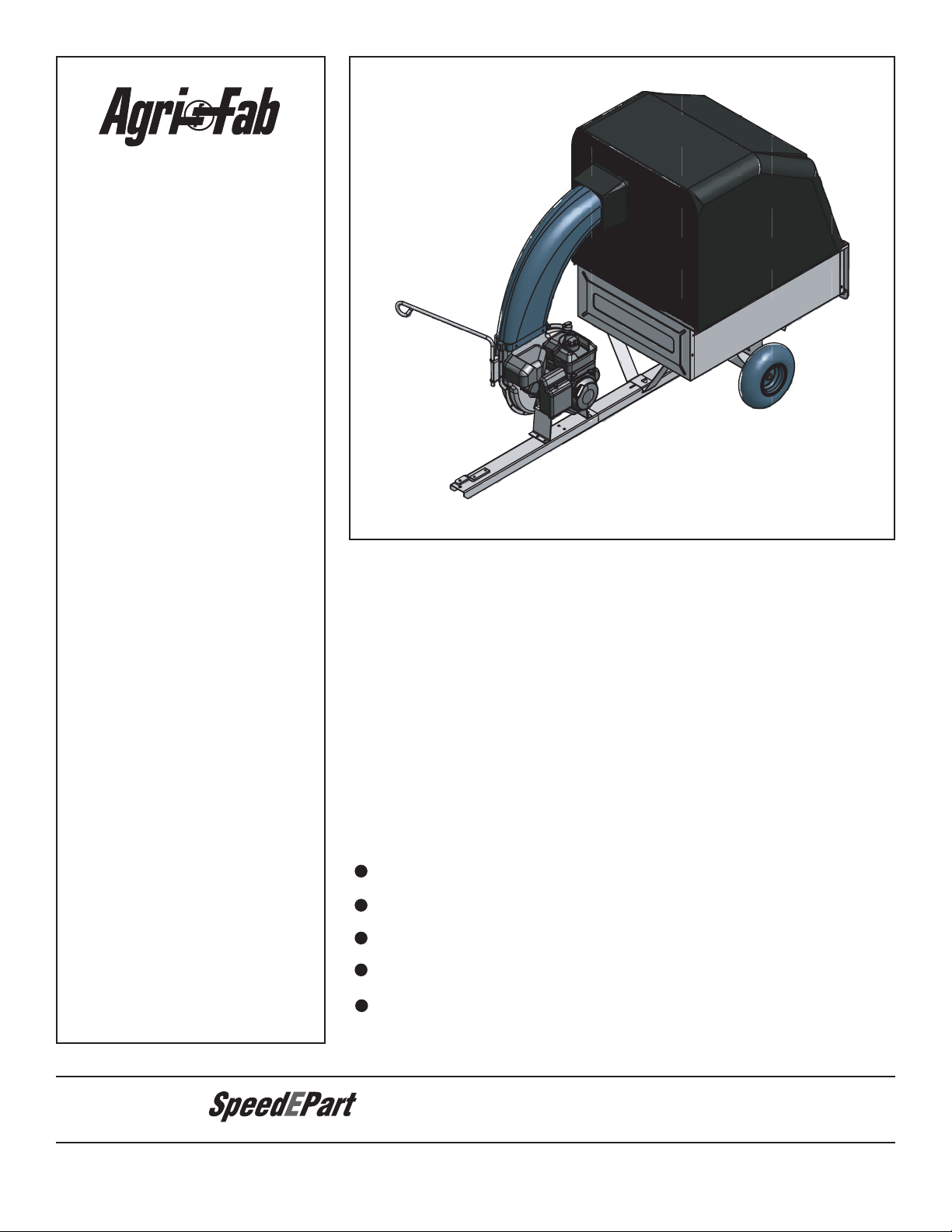
5.5 HP MOW-N-VAC
Read Rules for
Safe Operation
and Instructions
PRINTED IN USA
CAUTION:
Carefully
Safety
Assembly
Operating
Maintenance
Repair Parts
FORM NO. 40510 (4/25/07)

SAFETY RULES
Remember, any power equipment can cause injury if operated improperly or if the user does not understand how to operate
the equipment. Exercise caution at all times when using power equipment.
Look for this symbol to point out important safety precautions. It means — Attention!! Become alert!!
Your safety is involved.
• Read and follow all instructions in this manual before attempting
to assemble or operate this equipment. Failure to comply
with these instructions may result in personal injury. Keep this
manual in a safe place for future reference and for ordering
replacement parts.
• Read this operating and service instruction manual carefully.
Be thoroughly familiar with the controls and proper use of this
power vacuum.
• Read the vehicle owners manual and vehicle safe operation
rules before using this equipment.
• Never allow children under 16 to operate this Vac System.
Children 16 years and older should only operate under close
parental supervision.
• Do not allow anyone to operate this equipment without proper
instructions.
• Do not allow passengers to ride on this equipment or on the
towing vehicle.
• Keep the area of operation clear of others, particularly small
children and pets.
• Check fuel before starting engine. Do not ll fuel tank indoors,
or while engine is running or hot. Wipe off any spilled fuel
before starting engine.
• Engine and mufer get hot. Do not touch! To avoid re hazard,
keep clean of debris and other accumulations.
• Never store Vac System with fuel in tank. Allow engine to cool
before storing in any enclosure.
• Do not change engine governor settings.
• Do not operate engine if air cleaner or cover is removed,
except for adjustment. Removal of these parts could create
a re hazard.
• Keep hands, feet, face, long hair and clothing out of inlet and
discharge area. There are ROTATING BLADES inside these
openings.
• Before cleaning, repairing or inspecting, make certain all moving
parts come to a complete stop. Disconnect spark plug wire
and keep wire away from plug to prevent accidental starting.
Keep throttle control lever in stop position.
• If the Vac System should become blocked with debris at any
point, shut engine off and wait until the impeller comes to a
complete stop before attempting to remove the obstruction.
Disconnect spark plug wire to prevent accidental starting.
• If the cutting mechanism strikes a foreign object, or if your
Mow-n-vac should start to vibrate abnormally, stop the engine
immediately, disconnect the spark plug wire and move the wire
away from the spark plug. Allow the machine to stop and take
the following steps.
a. Inspect for damage.
b. Repair or replace any damaged parts.
c. Check for loose parts and tighten to assure
continued safe operation.
• Check all bolts for tightness at frequent intervals to help insure
safe operation.
• Check cart cover frequently for wear. Replace if worn or
damaged.
• Never operate Mow-N-Vac unless deck adapter, hose, hose
adapter (nozzle), discharge chute (elbow), and cart cover are
properly attached in their place.
• Do not remove cart cover or attempt to empty contents of cart
while engine is running.
• Never attempt to change hose adapter (nozzle) or to install
remote hose attachment when engine is running.
• Keep all shields and guards (e.g. discharge chute (elbow) and
hose adapter (nozzle) in place and securely attached.
• Always wear safety glasses or other suitable eye protection
when operating or maintaining this equipment.
• Do not stand behind cart in exhaust discharge area while
engine is running.
• Do not operate this equipment while intoxicated or while taking
drugs or medication that impairs the senses and reactions.
• When using this equipment, start with the vehicle transmission
in rst (low) gear and then gradually increase speed only as
conditions permit.
• Operate this equipment at reduced speed on rough terrain,
along creeks and ditches and on slopes to prevent tipping or
loss of control. Do not drive too close to a creek or ditch.
• Vehicle braking and stability are affected by the addition of
this equipment. Do not ll the Mow-N-Vac to its full capacity
without checking the capability of the towing vehicle to safely
pull and stop with the Mow-N-Vac attached.
• Before operating on any grade (hill) refer to the safety rules
in the vehicle owner’s manual concerning safe operation on
slopes. Also refer to the SLOPE GUIDE on page 25 of this
owner’s manual. Do not operate on slopes in excess of 10
degrees. STAY OFF STEEP SLOPES.
• Follow the maintenance instructions outlined in this manual.
DANGER: This Vac System was built to be operated according to the rules for safe operation in this
manual. As with any type of power equipment, carelessness or error on the part of the operator can result
in serious injury. This unit is capable of amputating ngers and hands and throwing objects. Failure to
observe the following safety instructions could result in serious injury or death.
2
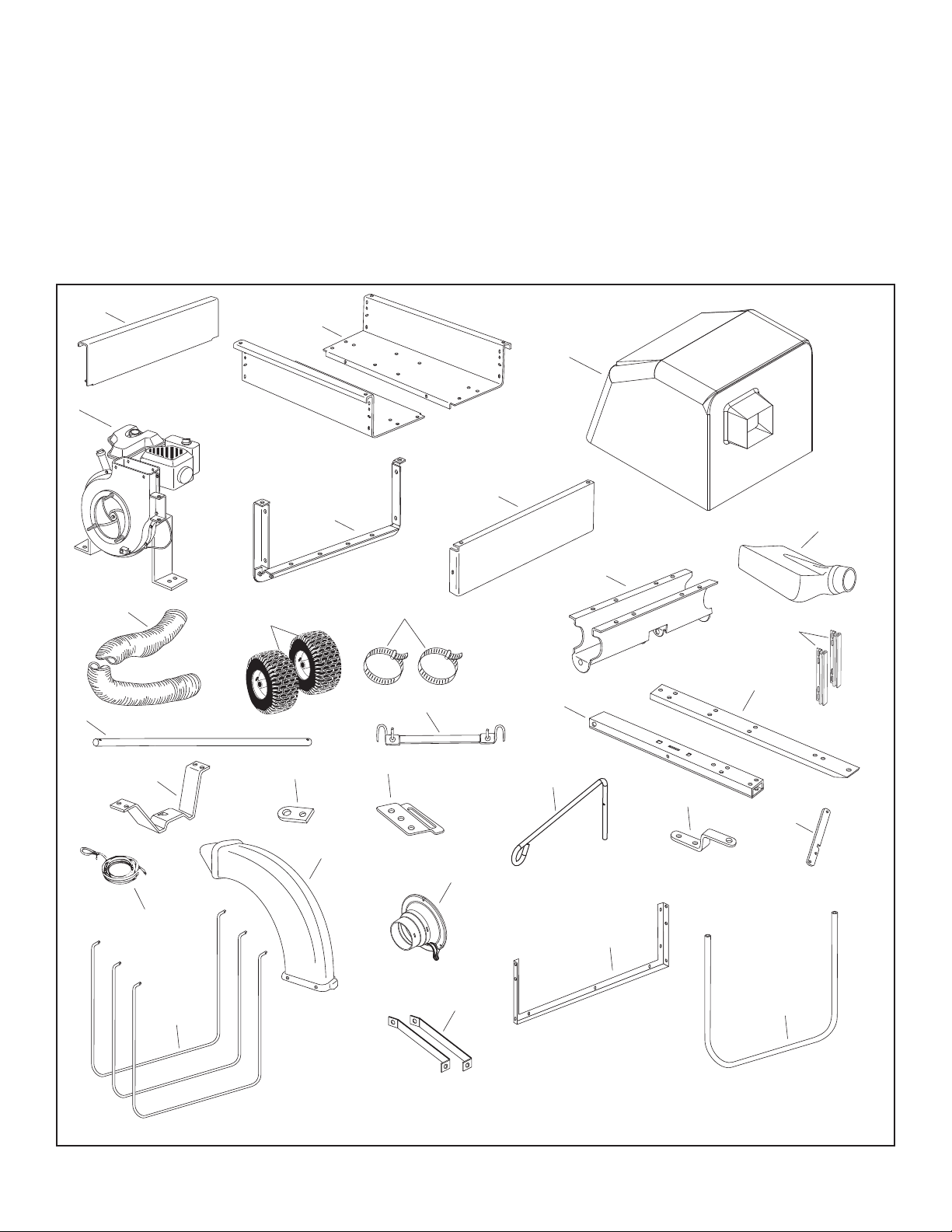
CARTON CONTENTS (NOT SHOWN FULL SIZE)
3
4
1
2
5
6
11
12
7
8
13
17
16
24
25
29
23
18
26
27
28
19
20
21
14
15
22
9
10
1. Tailgate
2. Cart Body (2)
3. Cart Cover
4. Engine
5. Tailgate Reinforcement Bracket
6. Front Panel
7. Mower Adapter
8. Hose
9. Wheel (2)
10. Hose Clamp (2)
11. Wheel Support
12. Tailgate Guide (2)
13. Axle
14. Tarp Strap, 25"
15. Rear Tongue
16. Front Tongue
17. Latch Stand Bracket
18. Hitch Plate
19. Adapter Bracket
20. Hose Hanger Rod
21. Hitch Bracket
22. Latch Lock Lever
23. Tailgate Rope
24. Deector w/ Elbow
25. Hose Adapter
26. Top Support Angle
27. Front Support Tube
28. Lower Support Rod (3)
29. Brace (2)
CARTON CONTENTS
3

NOT SHOWN FULL SIZE
A
B
C
J
R
T
U
S
V
W
P
AA
Z
CC
GG
DD
HH
EE
FF
JJ
KK
II
Y
L
M
N
O
D
E
F
G
H
I
Q
X
BB
K
HARDWARE PACK
4
HARDWARE PACK
REF. QTY. DESCRIPTION REF. QTY. DESCRIPTION
A 1 Hex Bolt, 5/16" x 4" T 8 Lock Nut, 1/4"
B 5 Hex Bolt, 3/8" x 3" U 1 Lock Nut, 5/16"
C 1 Hex Bolt, 1/2" x 1-1/4" V 4 Flat Washer
D 4 Hex Bolt, 3/8" x 1" W 2 Spacer
E 6 Hex Bolt, 1/4" x 1-1/4" X 1 Washer, 7/16" Std.
F 6 Hex Bolt, 1/4" x 1" Y 20 Washer, 1/4" Std.
G 4 Hex Bolt, 5/16" x 3/4" (self thread) Z 9 Nylon Washer
H 2 Hex Bolt, 5/16" x 1-1/4" AA 14 Washer, 5/16" Std.
I 2 Carriage Bolt, 5/16" x 3/4" BB 2 Hose Clip
J 23 Hex Bolt, 1/4" x 3/4" CC 1 Mounting Bracket
K 12 Truss Head Bolt, 5/16" x 3/4" DD 2 Tarp Strap
L 2 Slotted Head Bolt, 10-32 x 5/8" EE 1 Hitch Pin
M 1 Lock Nut, 1/2" FF 2 "S" Hook
N 9 Nylock Nut, 3/8" GG 1 Angle Bracket
O 1 Hair Cotter Pin, 3/32" HH 1 Spring
P 2 Cotter Pin, 1/8" x 1-1/4" II 3 Plastic Wing Nut
Q 2 Nylock Nut, 10-32 JJ 1 Mounting Strap
R 15 Nylock Nut, 5/16" KK 2 Axle Clip
S 33 Nylock Nut, 1/4"
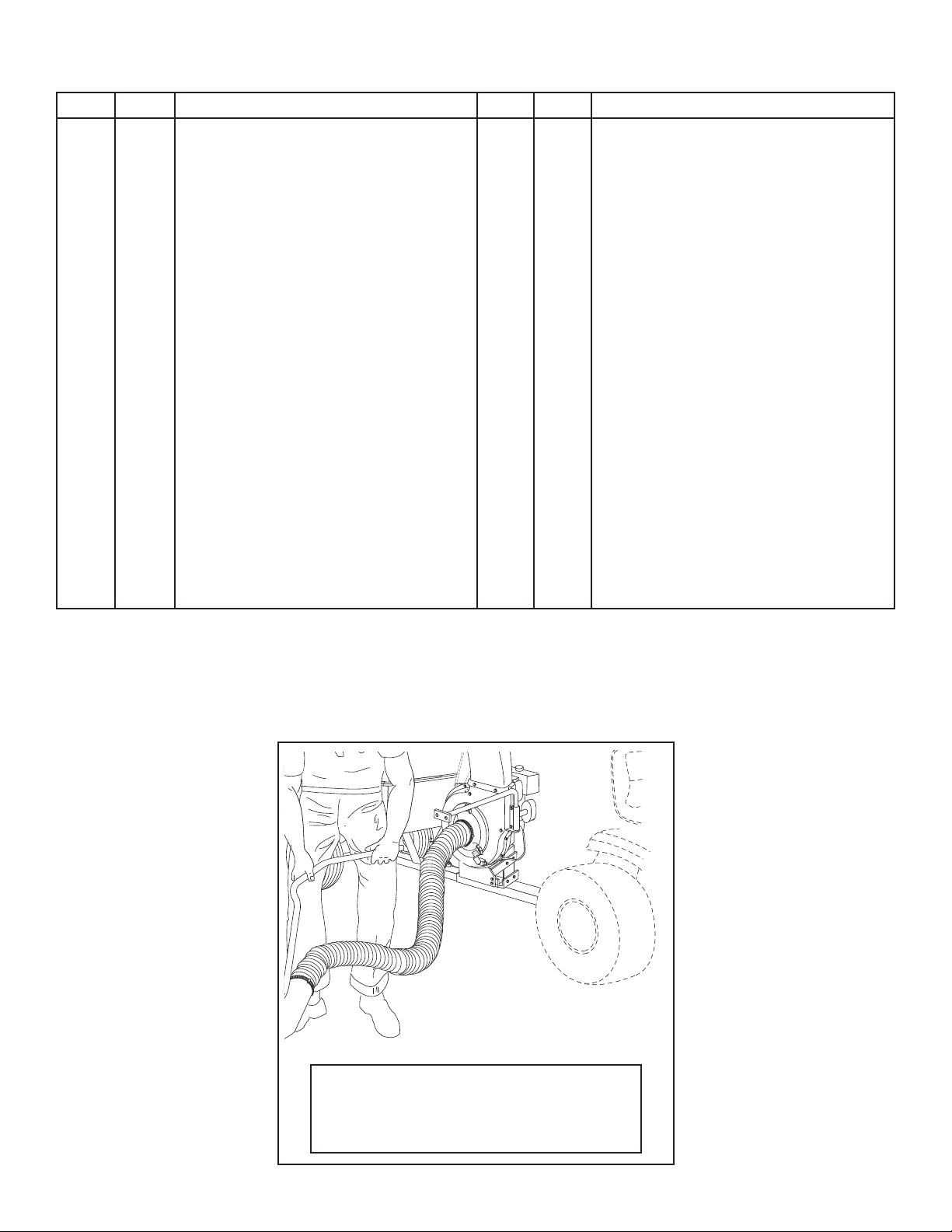
OPTIONAL ACCESSORY
MODEL NO. 45-0253
12 FT. REMOTE HOSE KIT
The Remote Hose Kit, Model 45-0253, provides
12' x 5" diameter hose to clean around shrubs,
patios, window wells and other areas not
accessible to the tractor.
5

ASSEMBLY INSTRUCTIONS
1/4" x 3/4" HEX BOLT
1/4" NYLOCK NUT
1/4" x 3/4"
HEX BOLT
5/16" x 3/4"
TRUSS HEAD BOLT
5/16" NYLOCK NUT
1/4" NYLOCK NUT
TAILGATE
REINFORCEMENT
BRACKET
TAILGATE GUIDE
PRE-ASSEMBLED BOLT
5/16" WASHER
SPACER
TAILGATE REINFORCEMENT BRACKET
TOOLS REQUIRED FOR ASSEMBLY
(2) 3/4" Wrench
(2) 9/16" Wrench
(2) 1/2" Wrench
(2) 7/16" Wrench
(1) Screwdriver
(1) Pliers
Spray adhesive is recommended for easier
assembly!
This unit is shipped WITHOUT GASOLINE or OIL. After
assembly, see separate engine manual for proper fuel and
engine oil recommendations.
CAUTION
DO NOT LEAVE THE MOW-N-VAC UNATTENDED
DURING ASSEMBLY. A FALLING MOW-N-VAC
CAN CAUSE PERSONAL INJURY! PAY CLOSE
ATTENTION TO THE STABILITY OF THE MOWN-VAC. ASSEMBLE ON A SMOOTH, LEVEL
SURFACE.
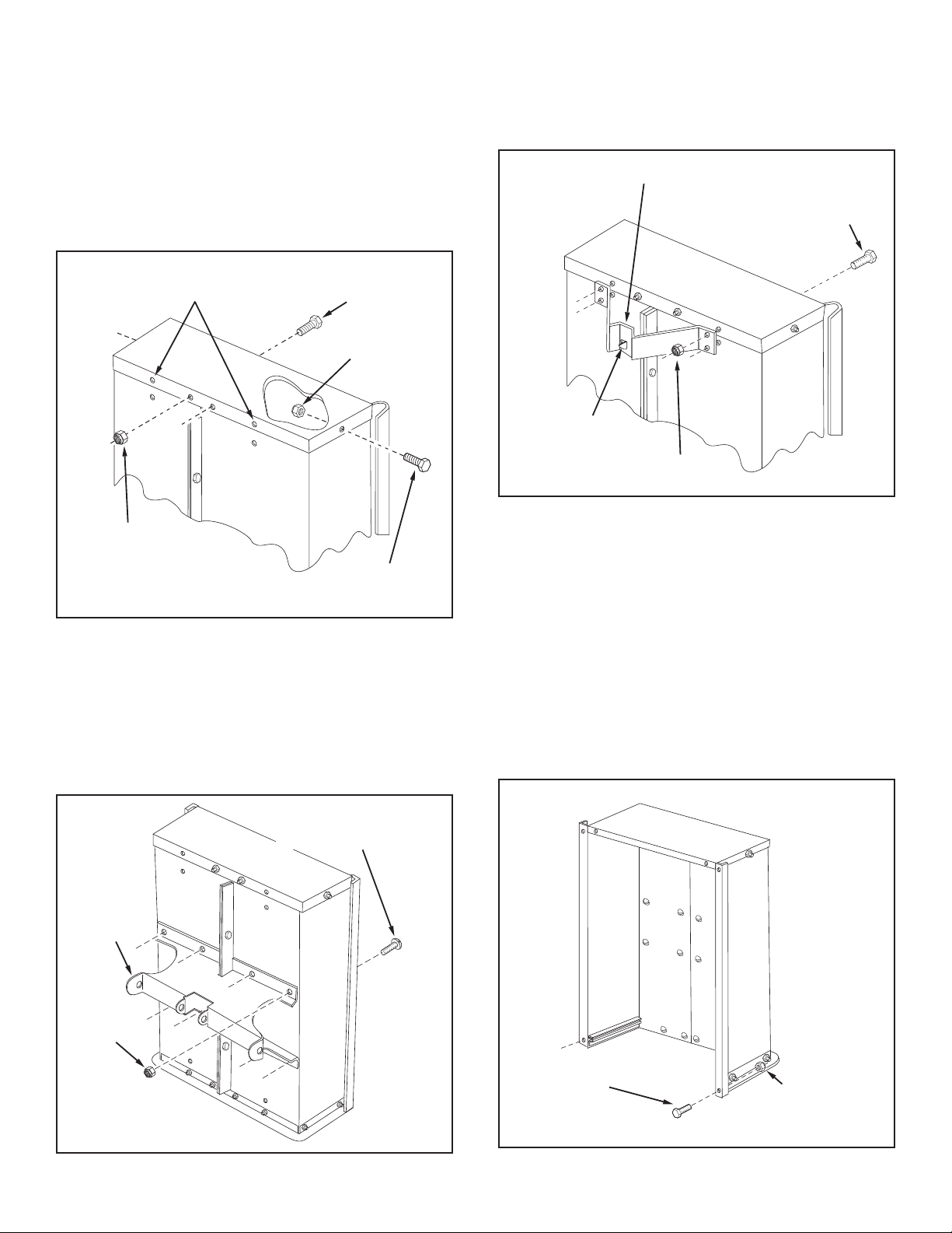
5. Position the tailgate reinforcement bracket on outside
of cart as shown in gure 2. Assemble to the bottom of
the cart body using four 5/16" x 3/4" truss head bolts
and 5/16" nylock nuts. Do not tighten. See gure 2.
6. Position the tailgate guides on the inside of the cart
bodies with guide channels to the front as shown in
gure 2. Assemble using four 1/4" x 3/4" hex bolts and
1/4" nylock nuts. Do not tighten.
7. At this time, with the cart body halves pulled together,
tighten the four truss head bolts assembled in step 5
and then tighten the four hex bolts assembled in step 6.
Do not tighten the two hex bolts that were assembled
in step 4.
1. Remove the hardware pack and all loose parts from the
carton. Be sure the carton is empty before discarding.
2. Lay out all the parts as shown in the carton contents.
3. Position cart body halves upright on a smooth level
surface such as a garage oor or a paved driveway. See
gure 1.
4. Assemble halves together using two 1/4" x 3/4" hex
bolts and 1/4" nylock nuts as shown in gure 1. Do not
tighten.
FIGURE 2
8. Remove the bottom two pre-assembled bolts in the
tailgate reinforcement bracket. Assemble a 5/16" washer
and spacer onto the bolt and reassemble it to the tailgate
reinforcement bracket. See gure 3.
FIGURE 1
FIGURE 3
6
9. Assemble the front panel over the opposite end of the
1/4" x 3/4"
HEX BOLT
1/4" x 3/4"
HEX BOLT
1/4" NYLOCK NUT
1/4" NYLOCK NUT
LEAVE HOLES OPEN FOR
LATCH STAND BRACKET
5/16"
NYLOCK
NUT
WHEEL
SUPPORT
5/16" x 3/4"
TRUSS HEAD BOLT
1/4" x 3/4"
HEX BOLT
LATCH STAND BRACKET
1/4" HEX NUT
ALIGNING TAB
AT BOTTOM
1/4" x 3/4"
HEX BOLT
1/4" NYLOCK
NUT
cart using four 1/4" x 3/4" hex bolts and 1/4" nylock
nuts as shown in gure 4. Leave two holes open in the
bottom of the panel as shown in gure 4. With the cart
body halves pulled together, tighten the two bolts in the
bottom of the front panel, then tighten the bolt in each
side.
At this time tighten the two bolts on the bottom of the
cart which were assembled in step 4.
11. Turn the latch stand bracket so that the aligning tab is
at the rear (bottom) of the bracket. Assemble the latch
stand bracket to the cart using four 1/4" x 3/4" hex bolts
and 1/4" nylock nuts. Tighten. See gure 6.
FIGURE 4
10. Assemble the wheel support to the cart using eight
5/16" x 3/4" truss head bolts and 5/16" nylock nuts as
shown in gure 5. Heads of bolts go on the inside of
cart. Tighten.
FIGURE 6
12. Assemble two 1/4" x 3/4" hex bolts and 1/4" nylock
nuts to the two rear corners of the cart. Tighten. See
gure 7.
FIGURE 5
FIGURE 7
7
AXLE
REAR
TONGUE
LATCH STAND
BRACKET
COTTER PIN
WHEEL
FLAT
WASHER
FLAT
WASHER
AXLE
AXLE
CLIP
TONGUE
(FRONT)
3/8" NYLOCK
NUT
3/8" x 1"
HEX BOLT
HITCH
BRACKET
5/16" x 4"
HEX BOLT
SPRING
LATCH
LOCK
LEVER
5/16" LOCK NUT
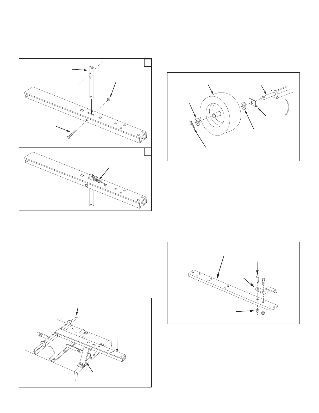
13. Insert the latch lock lever into the rear tongue as shown
in gure 8A. Secure it in place using the 5/16" x 4" hex
bolt and 5/16" nylock nut.
14. Attach the spring to the hole in the rear tongue and
the lower hole in the latch lock lever as shown in gure
8B.
A
B
IMPORTANT: Make sure drawbar tongue is securely
locked to the latch stand bracket by the latch lock lever.
17. Assemble a at washer, a wheel with the valve stem
facing out, another at washer and an axle clip onto
the axle as shown in gure 10. Secure the wheel on
the axle with a cotter pin, spreading the ends. Repeat
on other end of axle.
FIGURE 10
FIGURE 8
15. To prevent accidental tipping during the following
assembly procedures, lower the cart to rest upside down
on its top anges, so that the wheel support is facing
up. See gure 9.
16. Lay the drawbar tongue onto the Wheel Support and
the Latch Stand Bracket. Assemble the axle through
the wheel support and the tongue. See gure 9.
FIGURE 9
18. Assemble the hitch bracket to the front tongue using two
3/8" x 1" hex bolts and 3/8" nylock nuts. See gure 11.
FIGURE 11
8

3/8" x 1"
HEX BOLT
3/8" x 3"
HEX BOLT
3/8" NYLOCK NUT
HOSE HANGER ROD
19. Flip the cart over so that it rests on its wheels.
TONGUE
(FRONT)
3/8" x 3"
HEX BOLT
BLOCK
3/8" HEX
LOCK NUT
1/8" HAIR
COTTER PIN
HITCH PIN
NYLON WASHER
WING NUT
5/16" X 3/4"
HEX BOLT
(SELF TAP)
20. Assemble the front tongue on top of the rear tongue
using three 3/8" x 3" hex bolts and 3/8" hex lock nuts.
See gure 12.
HINT: For easier assembly, support the rear tongue with
a block of wood.
21. Assemble the hitch pin to the hitch bracket and tongue,
securing it with the 1/8" hair cotter pin. See gure 12.
24. Assemble the engine to the tongue using two 3/8" x 3"
hex bolts in the rear holes, two 3/8" x 1" hex bolts in the
front holes and four 3/8" nylock nuts. See gure 14.
HINT: Use caution when assembling engine to tongue. Have
another person assist you if you are having difculty.
HINT: For easier assembly, support the tongue with a block
of wood.
FIGURE 12
22. Attach the plastic elbow to the top of the engine housing
using four 5/16" x 3/4" hex bolts (self tapping) and nylon
washers. See gure 13.
HINT: Push in on hex bolts as you tighten to form threads.
23. Connect the hose adapter to the engine housing by
fastening three wing nuts to the pre-assembled bolts
in the engine housing. See gure 13.
FIGURE 14
25. Place the hose hanger rod down into the hose hanger
bracket on the impeller housing assembly. See gure
15.
FIGURE 13
FIGURE 15
9
 Loading...