

Page 1
Operator’s Manual
®
Grass Bag Kit
for the 33-inch Wide Cut Mower
Model No. 33731
CAUTION: Before using this product, read this manual and
follow all safety rules and operating instructions.
Sears, Roebuck and Co., Hoffman Estates, IL 60179, U.S.A.
Visit our web site: www.craftsman.com
FORM NO. 769-03115
3/26/2007
Page 2

TABLE OF CONTENTS
Warranty Statement .......................................................... 2
Assembly and Operation ..................................................3
WARRANTY STATEMENT
Repair Protection Agreements
Congratulations on making a smart purchase. Your new Craftsman®
product is designed and manufactured for years of dependable operation. But like all products, it may require repair from time to time. That’s
when having a Repair Protection Agreement can save you money and
aggravation. Here’s what’s included in the Agreement:
Expert service by our 12,000 professional repair specialists
•
Unlimited service and no charge for parts and labor on all covered
•
repairs
Product replacement if your covered product can’t be fixed
•
Discount of 10% from regular price of service and service-related
•
parts not covered by the agreement; also, 10% off regular price of
preventive maintenance check
Fast help by phone – phone support from a Sears technician on
•
products requiring in-home repair, plus convenient repair
scheduling
Español .............................................................................7
Service Numbers ............................................. Back Cover
Purchase a Repair Protection Agreement now and protect yourself
from unexpected hassle and expense.
Once you purchase the Agreement, a simple phone call is all that it
takes for you to schedule service. You can call anytime day or night, or
schedule a service appointment online.
Sears has over 12,000 professional repair specialists, who have
access to over 4.5 million quality parts and accessories. That’s the
kind of professionalism you can count on to help prolong the life of
your new purchase for years to come. Purchase your Repair Protection
Agreement today!
Some limitations and exclusions apply. For prices and additional
information call 1-800-827-6655.
Sears Installation Service
For Sears professional installation of home appliances, garage door
openers, water heaters, and other major home items, in the U.S.A. call
1-800-4-MY-HOME®
© Sears Brands, LLC
2
Page 3
ASSEMBLY AND OPERATION
WARNING
Before installing this accessory, shut the engine off and allow it to cool. Disconnect the spark plug wire from the spark plug. Refer to the
mower’s Operator’s Manual for complete safety instructions. Do not operate the mower without the entire grass bag in place. Turn the mower
off and disconnect the spark plug before emptying the grass bag.
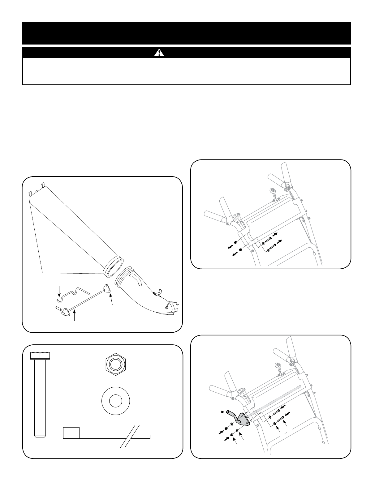
CARTON CONTENTS
Before installing this accessory, remove all parts from the carton.
Carton contents, including items included within the hardware pack,
are shown in Figures 1 and 2. Part numbers are shown in parentheses
and each item has been identified with a letter code, [X], for use when
following the assembly instructions. Reference to right or left side of
the mower is observed from the operating position.
TOOLS REQUIRED
Two 7/16” wrenches or two adjustable wrenches, and one set of pliers.
[A] - Grass bag (764-04052)
[B] - Chute
Assembly
(931-04239)
INSTALL THE RIGHT SIDE BRACKET
Shut off engine and disconnect the spark plug wire.
1.
Remove the Right Side Hardware
Remove the following from the right side of the upper handle,
2.
Figure 3. The hardware removed can be discarded.
Two 1/4-20 screws
•
Two flat washers
•
Two 1/4-20 cap lock nuts
•
[D] - Rod Hanger (747-04671)
[C] - Rod Assembly (647-04110-0637)
Figure 1
[F] - HH Cap Screw,
1/4-20 x 1.75” (Qty. 4)
(710-0136)
[I] - Cable Tie (Qty. 1)
(726-0209)
[E] - Rod Bracket
(787-01569-0637)
[G] - Lock Cap Nut,
1/4-20 (Qty. 4)
(712-0442)
[H] - Washer (Qty. 8)
(736-0463)
Figure 3
Install the Right Bracket
Align holes in rod assembly [C] with holes in panel and secure
3.
with the following items from the hardware pack, Figure 4:
Two 1/4-20 x 1.75” screws [F]
•
Four flat washers [H]
•
Two 1/4-20 cap lock nuts [G]
•
C
F
H
H
G
Figure 2 - Contents of the hardware pack.
Figure 4
3
Page 4
ASSEMBLY AND OPERATION
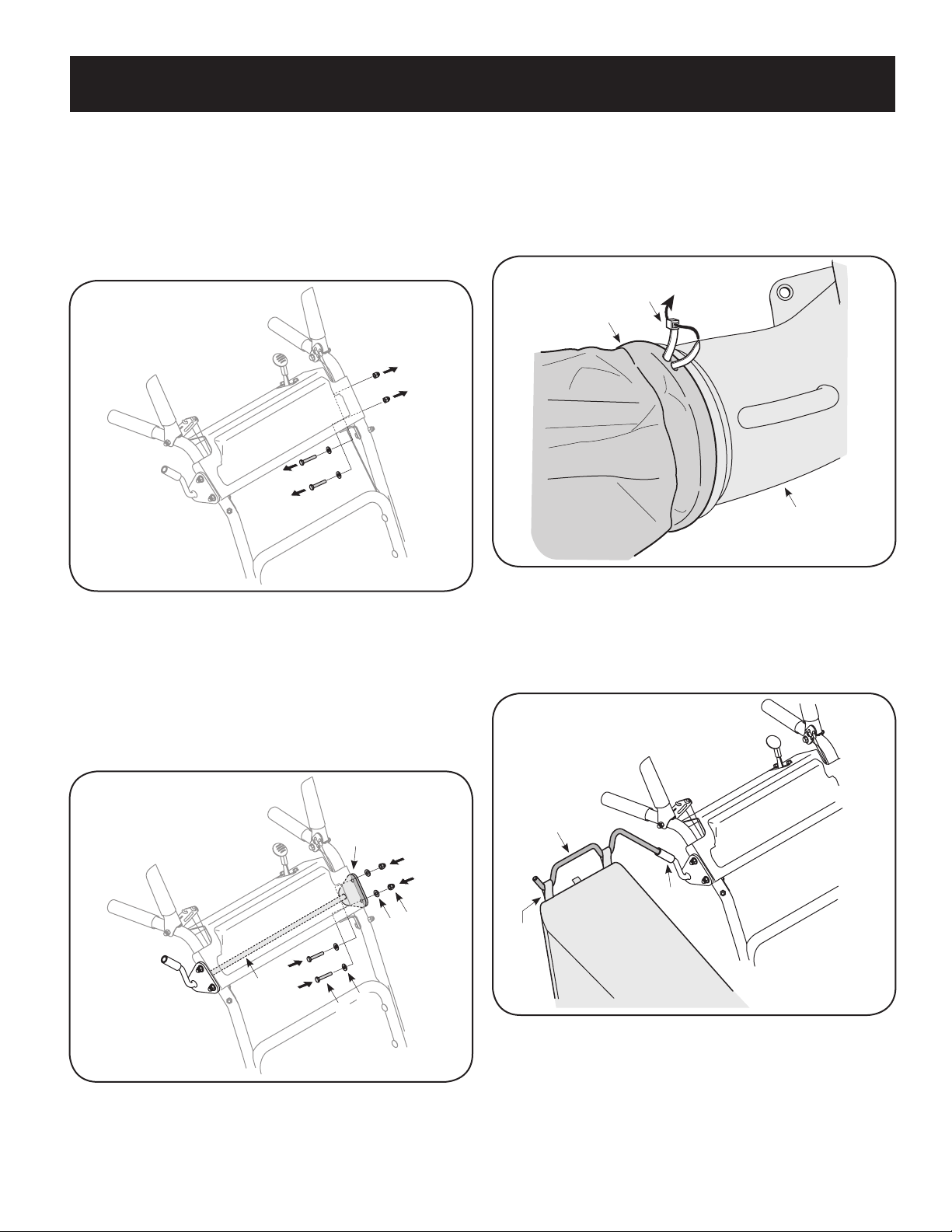
INSTALL THE LEFT SIDE BRACKET
Remove the Left Side Hardware
Remove the following from the left side of the upper handle,
1.
Figure 5. The hardware removed can be discarded.
Two 1/4-20 screws
•
Two flat washers
•
Two 1/4-20 cap lock nuts
•
Figure 5
Install the Left Bracket
Align holes in rod bracket [E] with holes in panel while placing end
2.
of rod assembly [C] through the bracket. Secure with the following
items from the hardware pack, Figure 6:
Two 1/4-20 x 1.75” screws [F]
•
Four flat washers [H]
•
Two 1/4-20 cap lock nuts [G]
•
ASSEMBLE THE GRASS BAG
Place grass bag [A] over chute assembly [B], Figure 7.
1.
Use the cable tie [I] to secure bag to chute assembly by inserting
2.
the cable tie into hole in bag and pulling through. Make sure cable
is positioned so it ties bag around indented groove (over flange)
of chute, Figure 7. Pull cable tight with pliers.
I
A
B
Figure 7
ATTACH THE ROD HANGER
Insert rod hanger [D] into the opening in the rod assembly [C],
1.
Figure 8.
Slide the tabs on the grass bag over the bag hanger rod, Figure 8.
2.
C
Figure 6
E
G
H
H
F
D
C
Tabs
Figure 8
4
Page 5

ASSEMBLY AND OPERATION
WARNING
Before installing this accessory, shut the engine off and allow it to cool. Disconnect the spark plug wire from the spark plug. Refer to the
mower’s Operator’s Manual for complete safety instructions. Do not operate the mower without the entire grass bag in place. Turn the mower
off and disconnect the spark plug before emptying the grass bag.
WARNING
The operation of any lawn mower can result in foreign objects being thrown into the eyes, which can damage your eyes severely. Always wear
safety glasses while operating the mower, or while performing any adjustments or repairs on it.
ATTACH THE GRASS BAG ASSEMBLY
Shut the engine off and disconnect spark plug. Lift the chute deflector on the deck back towards engine, Figure 9.
1.
Place the bottom lip of the chute/grass bag assembly into the lip on the deck, Figure 9.
2.
Place the tab of the chute/grass bag assembly into the bracket on the deck, Figure 9
3.
Lift chute/grass bag to position hole in chute over stud on the deck. The bracket on the chute will hold the chute deflector into an upright
4.
position, Figure 9
Push the latch over the bracket on the deck, Figure 9.
5.
1
2
4
3
5
Figure 9
USING THE GRASS BAG
Empty the bag when 3/4 full.
To remove the grass bag, lift discharge chute, lift chute/bag assembly from stud and remove assembly from opening in deck. After the grass
1.
bag assembly has been removed from the mower’s deck, remove the grass bag assembly (along with the hanger rod) from the right side
support.
Unzip the bag and empty.
2.
Zip the bag closed and reinstall entire assembly following “Attaching the Grass Bag Assembly” above. Check the grass bag frequently for
3.
deterioration and wear. Replace worn bag with new bag.
5
Page 6

NOTES
6
Page 7

ÍNDICE
Declaración de garantía .................................................... 6
Asamblea y Operación ......................................................8
Número de servicio ............................... Cubierta posterior
DECLARACIÓN DE GARANTÍA
Acuerdos de protección sobre reparaciones
Felicitaciones por haber realizado una adquisición inteligente. El
producto Craftsman® que ha adquirido está diseñado y fabricado
para brindar muchos años de funcionamiento confiable. Pero como
todos los productos a veces puede requerir de reparaciones. Es en
ese momento cuando el disponer de un Acuerdo de protección para
reparaciones le puede ahorrar dinero y
problemas. El Acuerdo incluye:
Servicio experto prestado por nuestros 12.000 especialistas en
•
reparaciones profesionales
Servicio ilimitado sin cargo para las piezas y la mano de obra en
•
todas las reparaciones cubiertas
Reemplazo del producto si no es posible reparar el producto
•
cubierto
Descuento de 10% sobre el precio normal del servicio y de las
•
piezas relacionadas con el mismo que no estén cubiertas por el
acuerdo; además, 10% de descuento sobre el precio normal de la
verificación de mantenimiento preventivo
Ayuda rápida por teléfono – asistencia telefónica a cargo de un
•
técnico de Sears para los productos que requieren reparación
a domicilio, además de una conveniente programación de la
reparación
Adquiera ahora un acuerdo de protección para reparaciones y
protéjase de problemas y gastos inesperados.
Una vez adquirido el acuerdo, puede programar el servicio con
tan sólo realizar una llamada telefónica. Puede llamar en cualquier
momento del día o de la noche, o programar un servicio en línea.
Sears dispone de más de 12.000 especialistas en reparaciones
profesionales que tienen acceso a más de 4.5 millones de piezas
y accesorios de gran calidad. Éste es el tipo de profesionalismo en
el que puede confiar para que le ayude a prolongar la vida útil del
producto recientemente adquirido durante muchos años. ¡Adquiera
hoy su acuerdo de protección para reparaciones!
Se aplican determinadas limitaciones y exclusiones. Para obtener
precios e información adicional llame al 1-800 -827-6655.
Servicio de instalación de Sears
Para instalación de artefactos domésticos, dispositivos de apertura de
portones de garage, calentadores de agua, y otros artículos del hogar
por profesionales de Sears, en los Estados Unidos llame al
1-800-4-MY-HOME®
© Sears Brands, LLC
7
Page 8

MONTAJE Y FUNCIONAMIENTO
ADVERTENCIA
Antes de instalar este accesorio, apague el motor y deje que se enfríe. Desconecte el cable de la bujía. Lea el Manual del Operador de la
cortadora de césped para conocer todas las instrucciones de seguridad. No opere la cortadora de césped si la bolsa de recolección no está
completamente en su lugar. Apáguela y desconecte la bujía antes de vaciar la bolsa de recolección.
CONTENIDO DE LA CAJA
Antes de instalar este accesorio, saque todas las piezas de la caja. El
contenido de la caja, incluidas las piezas del paquete de elementos
de ferretería, se muestra en las Figuras 1 y 2. Los números de las
piezas aparecen entre paréntesis y cada elemento ha sido identificado
con un código de letra, [X], que debe usarse para seguir las instrucciones de montaje. Las referencias a los lados derecho o izquierdo
de la cortadora de césped se hacen observando la máquina desde la
posición de operación.
HERRAMIENTAS NECESARIAS
Dos llaves de 7/16” o dos llaves ajustables y un par de pinzas.
[A] - Bolsa recolectora (764-04052)
INSTALACIÓN DE LA MÉNSULA DERECHA
Apague el motor y desconecte el cable de la bujía.
1.
Saque las piezas de ferretería del lado derecho
Saque los siguientes elementos del lado derecho de la barra de
2.
control superior, Figura 3. Se puede desechar los elementos de
ferretería extraídos.
Dos tornillos 1/4-20, Dos tornillos 1/4-20, Dos arandelas planas
[D] - Varilla de suspensión (747-04671)
[C] - Montaje de varillas (647-04110)
Figura 1
[F] - Tornillo
hexagonal, 1/4-20 x
1.75” (Cantidad 4)
(710-0136)
[E] - Ménsula de la
varilla (787-01569)
[G] - Tuerca de
seguridad, 1/4-20
(Cantidad 4)
(712-0442)
[H] - Arandela
(Cantidad 8) (736-0463)
[B] - Conjunto
del canal
(631-04239)
Figura 3
Instalación de la ménsula derecha
Se debe alinear los orificios del montaje de varillas [C] con los
3.
del panel y sujetarlos con las siguientes piezas del paquete de
ferretería, Figura 4:
Dos tornillos 1/4-20 x 1.75” [F]
•
Cuatro arandelas planas [H]
•
Dos tuercas de seguridad 1/4-20 [G]
•
C
[I] - Unión de cable (Cantidad 1) (726-0209)
Figura 2 – Contenido del paquete de elementos de ferretería.
F
H
H
G
Figura 4
8
Page 9

MONTAJE Y FUNCIONAMIENTO
INSTALACIÓN DE LA MÉNSULA IZQUIERDA
Saque las piezas de ferretería del lado izquierdo
Saque los siguientes elementos del lado izquierdo de la barra de
1.
control superior, Figura 5. Se puede desechar los elementos de
ferretería extraídos.
Dos tornillos 1/4-20
•
Dos arandelas planas
•
Dos tuercas de seguridad 1/4-20
•
MONTAJE DE LA BOLSA DE RECOLECCIÓN
Coloque la bolsa de recolección [A] sobre el conjunto del canal
1.
[B], Figura 7.
Use la unión de cable [I] para sujetar la bolsa al conjunto del
2.
canal insertando la unión de cable en el orificio de la bolsa y
empujándola para que pase. Verifique que el cable esté en
posición de manera que sujete la bolsa alrededor de la ranura
dentada (sobre la brida) del canal, Figura 7. Ajuste bien tirante el
cable con las pinzas.
I
A
B
Figura 5
Instalación de la ménsula izquierda
Se debe alinear los orificios de la ménsula de la varilla [E] con los
2.
del panel mientras se coloca el extremo del montaje de varillas
[C] a través de la ménsula. Asegúrelos con las siguientes piezas
del paquete de elementos de ferretería, Figura 6:
Dos tornillos 1/4-20 x 1.75” [F]
•
Cuatro arandelas planas [H]
•
Dos tuercas de seguridad 1/4-20 [G]
•
E
G
H
C
H
F
Figura 7
INSTALACIÓN DE LA VARILLA DE SUSPENSIÓN
Inserte la varilla de suspensión [D] en la abertura del montaje de
1.
varillas [C], Figura 8.
2 Deslice las lengüetas de la bolsa de recolección sobre la varilla
2.
de suspensión de la bolsa, Figura 8.
D
C
Tabs
Figura 6
Figura 8
9
Page 10

MONTAJE Y FUNCIONAMIENTO
ADVERTENCIA
Antes de instalar este accesorio, apague el motor y deje que se enfríe. Desconecte el cable de la bujía. Lea el Manual del Operador de la
cortadora de césped para conocer todas las instrucciones de seguridad. No opere la cortadora de césped si la bolsa de recolección no está
completamente en su lugar. Apague la cortadora de césped y desconecte la bujía antes de vaciar la bolsa de recolección.
ADVERTENCIA
Al operar una cortadora de césped puede ser que objetos extraños sean arrojados a los ojos, lo cual puede dañarlos gravemente. Utilice
siempre gafas de seguridad durante la operación de la cortadora de césped o mientras la ajusta o repara.
INSTALACIÓN DEL CONJUNTO DE LA BOLSA DE RECOLECCIÓN
Apague el motor y desconecte la bujía. Levante el deflector del canal de la plataforma para atrás hacia el motor, Figura 9.
1.
Coloque el borde inferior del conjunto de la bolsa de recolección / canal dentro del borde de la plataforma, Figura 9.
2.
Coloque la lengüeta del conjunto de la bolsa de recolección / canal dentro de la ménsula de la plataforma, Figura 9
3.
Levante la bolsa de recolección / canal para ubicar el orificio del canal sobre el pasador de la plataforma. La ménsula del canal sostendrá el
4.
deflector del canal en posición vertical, Figura 9
Pase el sujetador sobre la ménsula de la plataforma, Figura 9.
5.
1
2
4
3
5
Figura 9
USO DE LA BOLSA DE RECOLECCIÓN
Vacíe la bolsa cuando se llene 3/4 de la misma.
Para sacar la bolsa de recolección, levante el canal de descarga, levante el conjunto de la bolsa / canal del perno y saque el montaje de la
1.
abertura de la plataforma. Después de sacar el conjunto de la bolsa de recolección de la plataforma de la cortadora de césped, saque dicho
conjunto (junto con la varilla de suspensión) del soporte derecho.
Abra el cierre de la bolsa y vacíela.
2.
Cierre la bolsa y vuelva a instalar todo el conjunto siguiendo las instrucciones incluidas en “Instalación del conjunto de la bolsa de recolección”
3.
que figura más arriba. Controle frecuentemente la bolsa de recolección para detectar si se deteriora o desgasta. Cambie la bolsa gastada por una
nueva.
10
Page 11

NOTAS
11
Page 12

® Registered Trademark / TM Trademark /SM Service Mark of Sears Brands, LLC
® Marca Registrada / TM Marca de Fábrica / SM Marca de Servicio de Sears Brands, LLC
MC
Marque de commerce / MD Marque déposée de Sears Brands, LLC © Sears Brands, LLC
Get it fixed, at your home or ours!
Your Home
For repair – in your home – of all major brand appliances,
lawn and garden equipment, or heating and cooling systems,
no matter who made it, no matter who sold it!
For the replacement parts, accessories and
owner’s manuals that you need to do-it-yourself.
For Sears professional installation of home appliances
and items like garage door openers and water heaters.
1-800-4-MY-HOME
®
(1-800-469-4663)
Call anytime, day or night (U.S.A. and Canada)
www.sears.com www.sears.ca
For expert home solutions advice: www.managemyhome.com
Our Home
For repair of carry-in items like vacuums, lawn equipment,
and electronics, call or go on-line for the location of your nearest
Sears Parts & Repair Service Center
1-800-488-1222 (U.S.A.) 1-800-469-4663 (Canada)
Call anytime, day or night
www.sears.com www.sears.ca
To purchase a protection agreement on a product serviced by Sears:
1-800-827-6655 (U.S.A.) 1-800-361-6665 (Canada)
Para pedir servicio de reparación
a domicilio, y para ordenar piezas:
1-888-SU-HOGAR
®
(1-888-784-6427)
Au Canada pour service en français:
1-800-LE-FOYER
MC
(1-800-533-6937)
www.sears.ca
 Loading...