

Sears 153.336150, 153.336250, 153.336311, 153.336350, 153.336411 Owner's Manual
...
I
SWARS
Owners
Manual
FOR POTABLEWATER
HEATING ONLY
NOT SUITABLEFOR
SPACEHEATING
NOT FOR USE IN
MOBILE HOMES
Model No.
153.336150 30 Gal.
153.336250 40 Gal.
153,33631I 30 Gal, High Altitude
t53,336350 30 Gal.
153.336411 40 Gal. High Altitude
153.336450 40 Gal.
153.33651I 50 Gal. High Altitude
153.336550 50 Gal,
153.336750 30 GaL Propane (L.R)
153.3368I l 40 Gal. Propane (LP.)
High Altitude
153.336850 40 Gal, Propane (L,P)
Caution:
Read and Follow
All Safety Rules and
Operating Instructions
Before First Use of
This Product.
Save this Manual for Future Reference.
POWER MlSER 6
GAS WATER HEATER
• Safety Instructions
• Installation
• Operation
For Your Safety
AN ODORANT iS ADDED TO THE GAS USED BY THIS
WATER HEATER
• Care and Maintenance
• Troubleshooting
• Parts List
WARNING: if the information in these instructions are not fol-
lowed exactly, a fire or explosion may result, causing property
damage, personal injury or death.
-Do not store or use gasoline or other flammable vapors and liquids
in the vicinity of this or any other appliance.
-WHAT TO DO IF YOU SMELL GAS
• Do not try to light any appliance.
, Do not touch any electrical switch; do not use any phone in your
building.
• Immediately call your gas supplier from a neighbor's phone.
Follow the gas supplier's instructions.
° If you can not reach your gas supplier, call the fire department.
-Installation and service must be performed by a qualified installer,
service agency or the gas supplier.
AWARNING
Improper installation, adjustment, alteration, servlce or maintenance can
cause DEATH, SERIOUS BODILY INJURY,OR PROPERTY DAMAGE. Refer to
this manual for assistanceor consult the local Sears Service Center or gas util-
ity for further nformation.
_WARNING
Flammable vapors may be drawn by air currents from other areas of the
structure to this appliance.
AWARNING
READ THE GENERAL SAFETY SECTION BEGINNING ON INSIDE COVER
AND THEN THIS ENTIRE MANUAL BEFORE INSTALLING OR OPERAT-
ING THIS WATER HEATER.
Sears, Roebuck and Co., Hoffman Estates, IL 60179 U.S.A.
Safety
recautions
_WARNING
Improper installation, adjustment, a|teration, service or
maintenance can cause DEATH, SERIOUS BODILY
INJURY, OR PROPERTY DAMAGE. Refer to this manu-
al for assistance or consult your local Sears Service
Center for further information.
AWARNING
WATER HEATERS EQUIPPED FOR ONE TYPE GAS
ONLY: This water heater is equipped for one type gas
only. Check the model rating plate near the gas control
valve for the correct gas. DO NOT USE THIS WATER
HEATER WITH ANY GAS OTHER THAN THE ONE
SHOWN ON THE MODEL RATING PLATE. Failure to
use the correct gas can cause problems which can result in
DEATH, SERIOUS BODILY INJURY, OR PROPERTY
DAMAGE. if you have any questions or doubts consult
your gassupplier or local utility.
AWARNING
INSTALLATIONS IN AREAS WHERE FLAMMABLE LIQ-
UIDS (VAPORS) ARE LIKELY TO BE PRESENT OR
STORED (GARAGES, STORAGE, AND UTILITY AREAS,
ETC): Flammable tiquids (such as gasoline, solvents,
propane (LP) or butane, etc.), all of which emit flammable
vapors, may be improperly stored or used in such areas.
The gas water heater pilot light or main burner can ignite
such vapors. The resulting flashback and fire can cause
death or serious burns to anyone in the area, as well as
property damage.
If installation in such areas is your only option, then the
installation must be accomplished in a way that the pilot
flame and main burner flame are elevated from the floor
_t least 18 inches. While this may reduce the chances of
flammable vapors from a floor spill being ignited, gasoline
and other flammable substances should never be stored or
used in the same room or area containing a gas water
heater or other open flame or spark producing appliance.
NOTE: Flammable vapors may be drawn by air currents
from other areas of the structure to the appliance.
_WARNING
If this water heater will be used in beauty shops, barber
shops, cleaning establishments, or self-service laundries
with dry cleaning equipment, it is imperative that the
water heater or water heaters be installed so that com-
bustion and ventilation air be taken from outside these
areas. Refer to the "Locating The New Water Heater"
section of this manual and also the latest edition of the
National Fuel Gas Code, ANS! Z223.1, also referred to as
NFPA 54 for specifics provided concerning air required.
AWARNING
A fire can start if combustible materials such as clothing,
cleaning materials, or flammable liquids are placed against
or next to the water heater.
_WARNING
At the time of manufacture this water heater was pro-
vided with a combination temperature-pressures relief
valve certified by a nationally recognized testing labora-
tory that maintains periodic inspection of production of
listed equipment or materials, as meeting the require-
ments for Relief Valves and Automatic Gas Shutoff
Devices for Hot Water Supply Systems, and the latest
edition of ANSI Z21.22 and the code requirements of
ASME. If replaced, the valve must meet the require-
ments of local codes, but not less than a combination
temperature and pressure relief valve certified as meet-
ing the requirements for Relief Valves and Automatic
Gas Shutoff Devices for Hot Water Supply Systems,
ANSI Z21.22 by a nationally recognized testing laborato-
ry that maintains periodic inspection of production of
listed equipment or materials.
The valve must be marked with a maximum set pressure
not to exceed the marked hydrostatic working pressure
of the water heater (I 50 Ibs./sq. in.) and a discharge
capacity not less than the water heater input rate as
shown on the model rating plate. (Electric heaters -
watts divided by 1000 x 3415 equal BTU/Hr. rate.)
Your local jurisdictional authorlty_ while mandating the
use of a temperature-pressure relief valve complying
with ANSI Z21.22 and ASME, may require a valve model
different from the one furnished with the water heater.
Compliance with such local requirements must be satis-
fied by the installer or end user of the water heater with
a locally prescribed temperature-pressure relief valve
installed in the designated opening in the water heater in
_lace of the factory furnished valve.
For safe operation of the water heater, the relief valve
must not be removed from it's designated opening or
plugged.
The temperature-pressure relief valve must be installed
directly into the fitting of the water heater designated for
the relief valve. Position the valve downward and provide
tubing so that any discharge will exit only within 6 inches
above, or at any distance below the structural floor. Be
certain that no contact is made with any live electrical
part. The discharge opening must not be blocked or
reduced in size under any circumstances. Excessive
length, over 30 feet, or use of more than four elbows can
cause restriction and reduce the discharge capacity of
the valve.
No valve or other obstruction is to be placed between
the relief valve and the tank. Do not connect tubing
directly to discharge drain unless a 6" air gap is provided.
To prevent bodily injury, hazard to llfe, or property dam-
age, the relief valve must be allowed to discharge water
in quantities should circumstances demand, if the dis-
charge pipe is not connected to a drain or other suitable
means, the water flow may cause property damage.
The Discharge Pipe:
• Must not be smaller in size than the outlet pipe size of
the valve, or have any reducing couplings or other
restrictions.
• Must not be plugged or blocked.
• Must be of material listed for hot water distribution.
• Must be installed so as to allow complete drainage of
both the temperature-pressure relief valve, and the_"
discharge pipe. I
• Must terminate at an adequate drain.
• Must not have any valve between the relief valve and
tank.
Safety Precautions
AWARNING
A gas water heater cannot operate properly without the
correct amount of air for combustion. Do not install in a
confined area such a closet, unless you provide air as
shown in the "Locating The New Water Heater" section.
Never obstruct the flow of ventilation air. If you have any
doubts or questions at all, call your gas company. Failure
to provide the proper amount of combustion air can result
in a fire or explosion and can cause DEATH, SERIOUS
BODILY INJURY, OR PROPERTY DAMAGE.
_,WARNING
This water heater must not be installed directly on car-
peting. Carpeting must be protected by a metal or wood
panel beneath the appliance extending beyond the full
width and depth of the appliance by at least 3 inches
(76.2mm) in any direction, or if the appliance is installed
in an alcove or closet, the entire floor must be covered by
the panel. Failure to heed this warning may result in a
fire hazard.
_WARNING
HOTTER WATER CAN SCALD: Water heaters are
intended to produce hot water. Water heated to a tem-
perature which will satisfy clothes washing, dish washing,
and other sanitizing needs can scald and permanently
injure you upon contact. Some people are more likely to
be permanently injured by hot water than others. These
include the elderly, children, the infirm, or physically/men-
tally handicapped. If anyone using hot water in your home
fits into one of these groups or if there is a local code or
state law requiring a certain temperature water at the hot
water tap, then you must take special precautions. In addi-
tion to using the lowest possible temperature setting that
satisfies your hot water needs, a means such as a mixing
valve, should be used at the hot water taps used by these
oeople or at the water heater. Mixing valves are available
: plumbing supply or hardware stores. Follow manuFac-
.urers instructions for installation of the valves. Before
l changing the factory setting on the thermostat, read the
"Temperature Regulation" section in this manual.
AWARNING
Soot build-up indicates a problem that requires correc-
tion before further use. Turn "off" gas to water heater
and leave "off" until repairs are made, because Failure to
correct the cause of the sooting can result in a fire or
explosion causing DEATH, SERIOUS BODILY INJURY,
OR PROPERTY DAMAGE.
I
&WARNING
VENT DAMPERS - Any vent damper, whether it is operat-
ed thermally or otherwise must be removed if its use
inhibits proper drafting of the water heater.
Thermally Operated Vent Dampers: Gas-fired water
heaters having thermal efficiency in excess of 80% may
produce a relatively low flue gas temperature. Such tem-
peratures may not be high enough to properly open ther-
mally operated vent dampers. This would cause spillage of
flue gasesand may cause carbon monoxide poisoning.
Vent dampers must bear evidence of certification as com-
plying with the latest edition of American National
Standard ANSI Z21.68 (ANSI Z21.66 & 67, respectively,
cover electrically and mechanically actuated vent
dampers). Before installation of any vent damper, consult
your local Sears Service Center or the gas utility for fur-
ther information.
AWARNING
• The appliance and its individual shutoff valve must be dis-
connected from the gas supply piping system during any
pressure testing of the gas system at test pressures in
excess of I/2 pound per square inch (3.SEPa).
• The appliance must be isolated from the gas supply pip-
ing system by closing its individual manual shutoff valve
during any pressure testing of the gas supply piping sys-
tem at test pressures equal or less than I/2 pound per
square inch (3.5kPa),
_WARNING
BEFORE LIGHTING [PROPANE (L.P.) GAS WATER
HEATERS]: Propane (LR) gas is heavier than air. Should
there be a leak in the system, the gas will settle near the
ground. Basements, crawl spaces, skirted areas under
mobile homes (even when ventilated), closets and areas
below ground level will serve as pockets for the accumula-
tion of this gas. Before attempting to light or rellght the
water heater's pilot or turning on a nearby electrical light
switch, be absolutely sure there is no accumulated gas in
the area. Search for odor of gas by sniffing at ground level
......the vicinity of the appliance. If odor is detected, follow
_eps ndicated at "For Your Safety" on the cover page of
this manual then leave the premises.
_,WARNING
Chemical vapor corrosion of the flue and vent system
may occur if air for combustion contains certain chemical
vapors. Spray can propellants, cleaning solvents_ refrigera-
tor and air conditioner refrigerants, swimming pool
chemicals, calcium and sodium chloride, waxes, bleach,
and process chemicals are typical compounds which are
potentially corrosive.
AWARNING t
Obstructed or deteriorated vent systems may present a
serious health risk or asphyxiation.
Safety Precautions continued on page 4
3
Safety Precautions
AWARNING
The water heater with draft hood installed must be prop-
erly vented to a chimney which terminates outdoors.
Never operate the water heater unless it is vented to the
outdoors and has adequate air supply to avoid risks of
improper operation, explosion or asphyxiation.
_WARNING
Hinlmum clearances between the water beater and com-
bustible construction are I" at the sides and rear, 4" at the
front, and 6" from the vent pipe. Clearance from the top of the
jacket is 18" on most models. Note that a lesserdimension may
be allowed on some models. Refer to the label on the water
heater adjacent to the gascontrol valve for all clearances.
_CAUTION
WATER HEATERS EVENTUALLY LEAK: Installation ol
the water heater must be accomplished in such a manner
that if the tank or any connections should leak, the flow of
water will not cause damage to the structure. When such
locations cannot be avoided, a suitable drain pan should
be installed under the water heater. Drain pans are avail-
able at your local Sears store. Such a drain pan must be
not greater than I |/2 inches deep, have a minimum
length and width of at least 2 inches greater than the
water heater dimensions and must be piped to an ade-
quate drain. The pan must not restrict combustion air
flow. Under no circumstances is the manufacturer or
Sears to be held liable for any water damage in connec-
tion with this water heater.
I ,_WARNING t
Do not use this appliance if any part of it has been under I
water. Immediately call a Sears Service Technician to I
inspect the appliance and to replace the gascontrol or any I
part of the burner system which has been under water. I
AWARNING
HYDROGEN GAS: Hydrogen gas can be produced in a hot
water system that has not been used for a long period of
time (generally two weeks or more). Hydrogen gas is
extremely flammable and explosive. To prevent the possi-
bUity of injury under these conditions_ we recommend the
hot water faucet be opened for several minutes at the
kitchen sink before any electrical appliances which are
connected to the hot water system are used (such as a dis-
_washer or washing machine). If hydrogen gas is present,
there will probably be an unusual sound similar to air
escaping through the pipe as the hot water faucet is
opened. There must be no smoking or open flame near
the faucet at the time it is open.
_WARNING
INSULATING JACKETS: When installing an external
water heater insulation jacket on a gas water heater:
• DO NOT cover the temperature-pressure relief valve.
• DO NOT put insulation over any part of the top of the
gaswater heater.
• DO NOT put insulation over the gas control valve or gas
control valve/burner cover, or any access areas to the
burner.
• DO NOT let insulation around the gas water heater to
get within 8 inches of the floor (air must get to the
burner).
• DO NOT cover or remove operating instructions, and
safety related warning labels and materials affixed to the
water heater.
Failure to heed this will result in the possibility of a fire or
explosion.
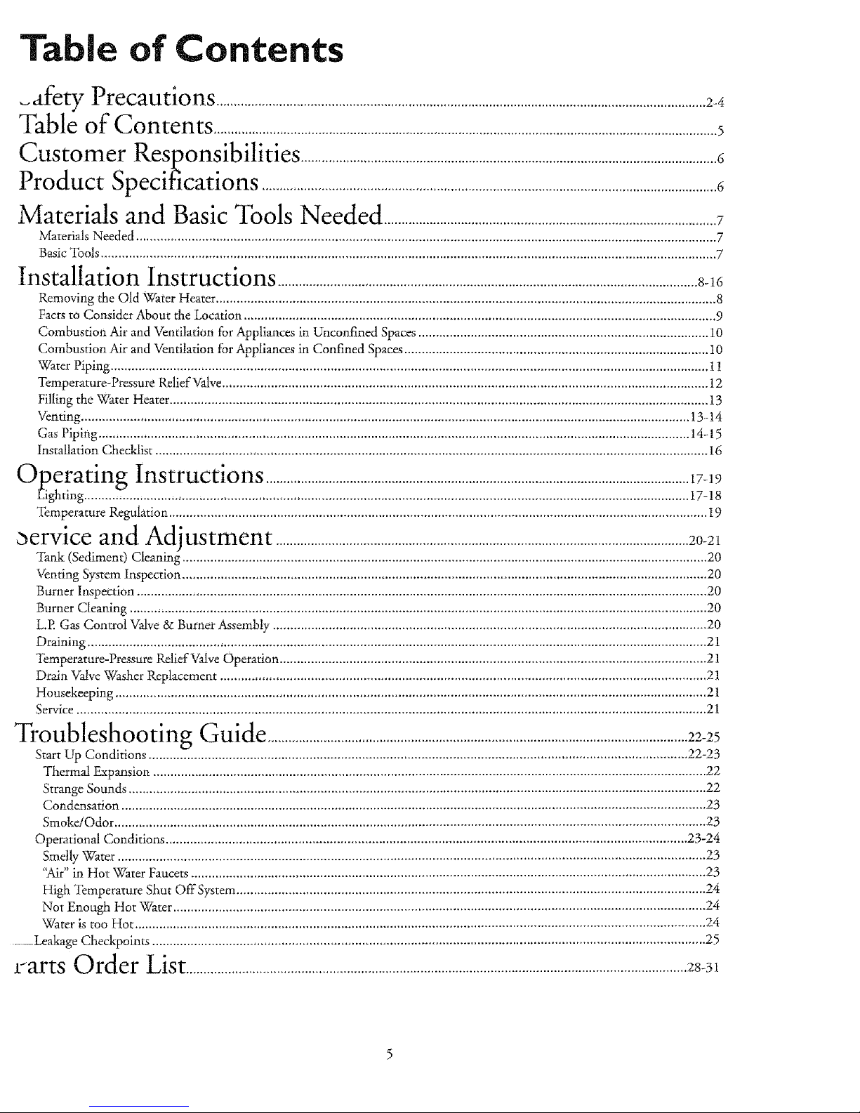
Table of Contents
_al_y¢_'_"Precautions ............................................................................................................................................ 24
Table of Contents ................................................................................................................................................5
Customer Responsibilities .......................................................................................................................6
Product Specifications ..................................................................................................................................6
Materials and Basic Tools Needed ...............................................................................................7
Materi_s Needed ...................................................................................................................................................................... 7
Basic Tools ................................................................................................................................................................................ 7
Installation Instructions ........................................................................................................................8-16
Removing the Old \Vater Heater ............................................................................................................................................... 8
Facts to Consider About the Location ....................................................................................................................................... 9
Combustion Air and Ventilation for Appliances in Unconfined Spaces ................................................................................... 10
Combustion Air and Ventilation for Appliances in Confined Spaces....................................................................................... 10
Water Piping ........................................................................................................................................................................... t 1
Temperature-Pressure Relief Valve........................................................................................................................................... 12
Filling the Water Heater .......................................................................................................................................................... 13
Venting .............................................................................................................................................................................. 13-14
Gas Piping ......................................................................................................................................................................... 14-15
Installation Checklist .............................................................................................................................................................. 16
OperatinR Instructions .........................................................................................................................I7-19
Eighting ............................................................................................................................................................................. 17-!8
Temperature Regulation .......................................................................................................................................................... 19
_ervice and Adjustment ...................................................................................................................... 20-21
Tank (Sediment) Cleaning ...................................................................................................................................................... 20
Venting System Inspection ...................................................................................................................................................... 20
Burner Inspection ................................................................................................................................................................... 20
Burner Cleaning ..................................................................................................................................................................... 20
L.P. Gas Control Valve & Burner Assembly ............................................................................................................................ 20
Draining ................................................................................................................................................................................. 21
Temperature-Pressure Relief ValveOperation .......................................................................................................................... 21
Drain VaJveWasher Replacement ........................................................................................................................................... 21
Housekeeping ......................................................................................................................................................................... 2 !
Service .................................................................................................................................................................................... 21
Troubleshooting Guide ........................................................................................................................22-25
Start Up Conditions .......................................................................................................................................................... 22-23
Thermal F_xpansion.............................................................................................................................................................. 22
Strange Sounds ..................................................................................................................................................................... 22
Condensation ....................................................................................................................................................................... 23
Smoke/Odor ......................................................................................................................................................................... 23
Operational Conditions ..................................................................................................................................................... 23-24
Smelly Water ........................................................................................................................................................................ 23
"Air" in Hot \rater Faucets ................................................................................................................................................... 23
High Temperature Shut Off System...................................................................................................................................... 24
Not Enough Hot Water ........................................................................................................................................................ 24
Water is too Hot ................................................................................................................................................................... 24
.... Leakage Checkpoints .............................................................................................................................................................. 25
tarts Order List............................................................................................................................................... 28-31
Customer
ponsibilities
,-,-ILlnanK You for purchasing a Sears water heater.
Properly installed and maintained, it should give you years of
trouble free service. If you should decide that you want the new
water heater professionally installed by Sears call the local Sears
Service Center or aW Sears store. They will arrange for prompt,
quality installation by Sears authorized contractors.
Abbreviations Found In This Instruction Manual
A.G.A. - American Gas Association
A.N.S.L -American National Standards Institute
AWARNING
This gas-fired water heater is design certified by the
American Gas Association Laboratories under American
National Standardsfor Gas Water Heaters, The installa-
tion must conformwith this manual,LocalCodesandwith
the latest edition of the National Fuel Gas Code, ANS!
Z223.I.
Thispublicationis availablefrom your localgovernmentor
public library, gas company, or by writing NFPA,
Batterymarch Park,Quincy,MA 02269.
• Read the "Safety Precautions" section, pages 2 through 4 of
this manual first and then the entire manual carefnll)_ If you
don't follow the safety rules, the water heater will not operate
properly. It could cause DEATH, SERIOUS BODILY
INJURY AND/OR PROPERTY DAMAGE.
• This manual contains instructions for the installation, op£
tion, and maintenance of the gas-fired water heater. It also
contains warnings through out tile manual that you must read
and be aware of, All warnings and ali instructions are essential
to the proper operation of the water heater and your safety.
Since we cannot put everything on the first few pages, READ
THE ENTIRE MANUAL BEFORE ATTEMPTING TO
INSTALL OR OPERATE THE WATER HEATER.
• The installation must confbrm with the instructions in this
manual; gas company rules; and Local Codes, or in the
absence of Local Codes, with the latest edition of the National
Fuel Gas code, ANSI Z223.1, also referred to as NFPA 54.
This publication is available from your local government or
public library or gas company or by writing NFPA,
gatterymarch Park, Quincy, MA 02269.
• If after reading this manual you have any questions or do not
understand any portion of the instructions, call the Sears
Service Center.
• Carefillly plan the place where you are going to put the water
heater. Correct combustion, vent action, mad vent pipe instal-
lation are very important in preventing death from possible
carbon monoxide poisoning and fires.
Examine the location to ensure the water heater complies with
the "Facts to Consider About the Location" section in this
manual,
o For California installation this water heater must be braced,
anchored, or strapped to avoid falling or moving during an
earthquake. See instructions for correct installation proce-
dures. Instructions may be obtained from your local dealer,
wholesaler, public utilities or California Office of the State
Architect, 400 P Street, Sacramento, CA 95814.
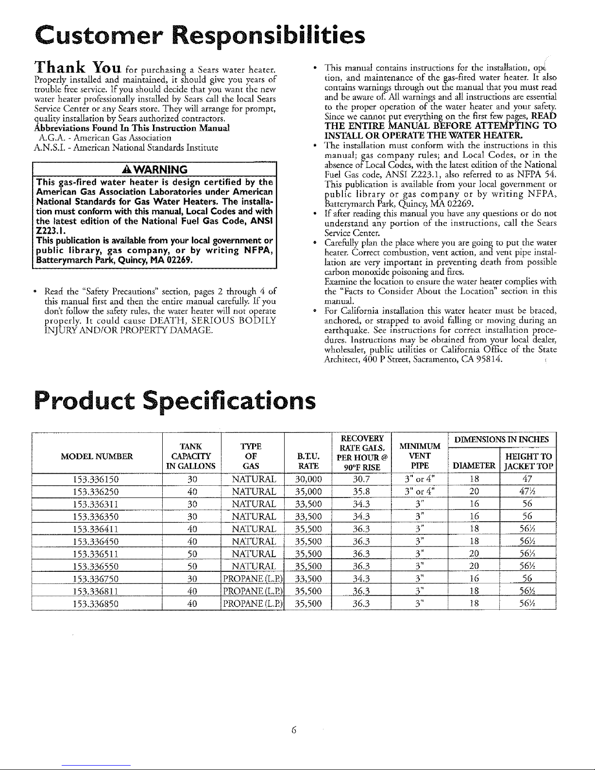
roduct Specifications
MODEL NUMBER
153.336150
153.336250
153.33631i
153.336350
153.336411
153.336450
153.336511
153.336550
153.336750
153.336811
153.336850
'lANK
CAPACITY
INGALLONS
30
40
30
30
40
40
50
50
30
40
40
TYPE
OF
GAS
NATURAL
NATURAL
NATURAL
NATURAL
NATURAL
NATURAL
NATURAL
NATURAL
PROPANE (L.P,
PROPANE (L.P.)
PROPANE (L.P.)
B.ZU.
RATE
30,000
35,000
33,500
33,500
35,500
35,500
35,5OO
35,500
33,500
35,500
35,50O
RECOVERY
RATEGALS.
PERHOUR @
90°FRISE
30,7
35.8
34.3
34.3
36.3
36.3
36.3
36.3
34.3
36.3
36.3
MINIMUM
VENT
PIPE
3" or 4"
3" or 4"
3"
3"
3"
3"
3"
3"
3"
3"
3"
DIMENSIONSININCHES
HEIGHTTO
DIAMETER JACKETTOP
18 47
2O 47_
16 56
16 56
18 56_
t8 56_
20 56_
20 56_
16 56
t8 56_
t8 56_
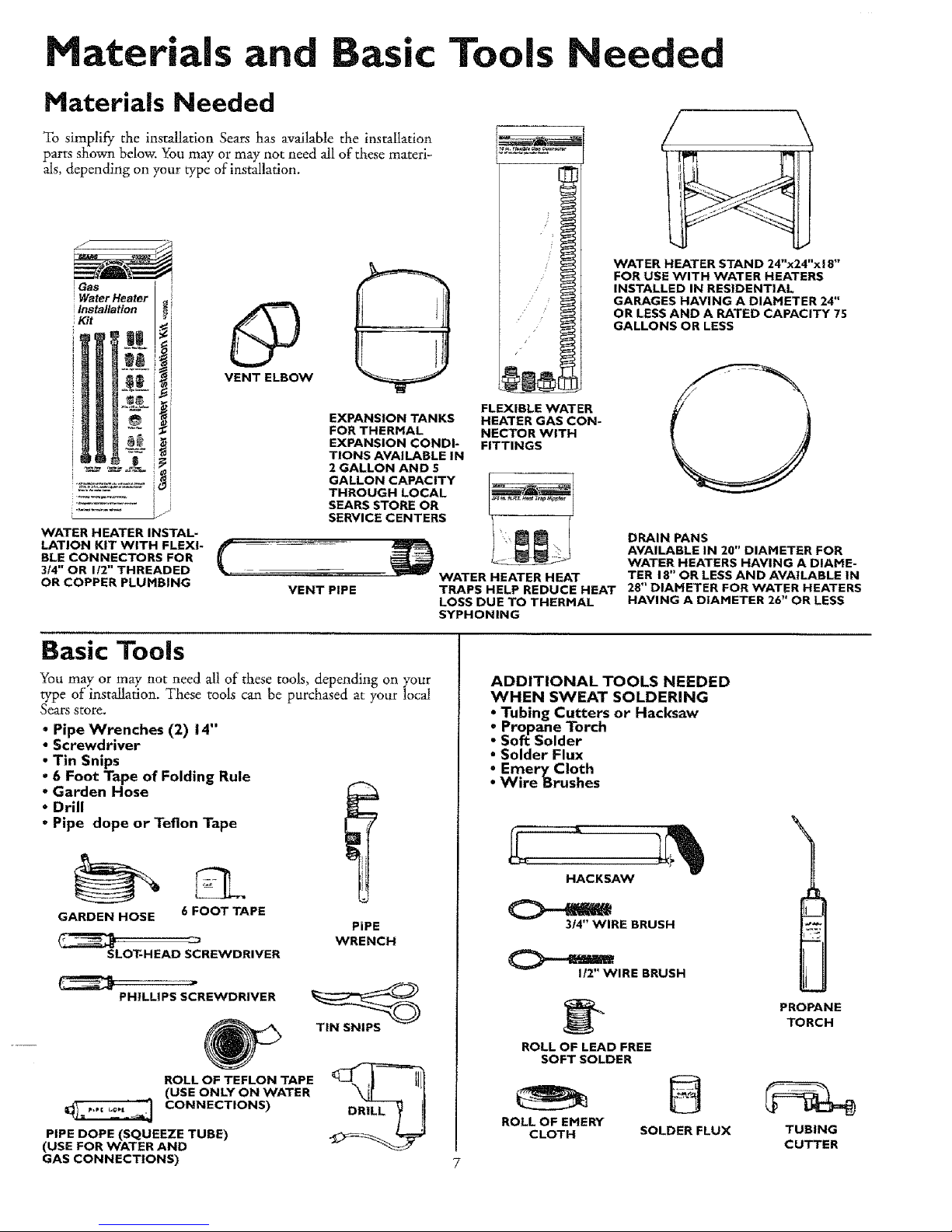
ateriais and Basic Tools Needed
Materials Needed
To simplify the installation Sears has available the installation
parts shown below. You may or may not need all of these materi-
als, depending on your type of installation.
Water Heater _ i
Installation _ i
i Kit
WATER HEATER INSTAL-
LATION KIT WITH FLEXI-
BLE CONNECTORS FOR
k
314" OR 1/2" THREADED
OR COPPER PLUMBING
O
VENT ELBOW
EXPANSION TANKS
FOR THERMAL
EXPANSION CONDI-
TIONS AVAILABLE IN
2 GALLON AND 5
GALLON CAPACITY
THROUGH LOCAL
SEARS STORE OR
SERVICE CENTERS
FLEXIBLE WATER
HEATER GAS CON-
NECTOR WITH
FITTINGS
VENT PIPE
WATER HEATER H EAT
TRAPS HELP REDUCE HEAT
LOSS DUE TO THERMAL
SYPHONING
WATER HEATER STAND 24"x24"x18"
FOR USE WITH WATER HEATERS
INSTALLED IN RESIDENTIAL
GARAGES HAVING A DIAMETER 24"
OR LESS AND A RATED CAPACITY 75
GALLONS OR LESS
DRAIN PANS
AVAILABLE IN 20" DIAMETER FOR
WATER HEATERS HAVING A DIAME-
TER 18" OR LESS AND AVAILABLE IN
28" DIAMETER FOR WATER HEATERS
HAVING A DIAMETER 26" OR LESS
Basic Tools
You may or may not need all of these tools, depending on your
type of installation. These tools can be purchased at your locaI
Sears store.
• Pipe Wrenches (2) 14"
• Screwdriver
• Tin Snips
• 6 Foot Tape of Folding Rule
• Garden Hose
• Drill
° Pipe dope or Teflon Tape
GARDEN HOSE 6 FOOT TAPE
SLOT-HEAD SCREWDRIVER
PiPE
WRENCH
PHiLLiPS SCREWDRIVER
ROLL OF TEFLON TAPE
(USE ONLY ON WATER
CONNECTIONS)
PIPE DOPE (SQUEEZE TUBE)
(USE FOR WATER AND
GAS CONNECTIONS)
TIN SNIPS
ADDITIONAL TOOLS NEEDED
WHEN SWEAT SOLDERING
• Tubing Cutters or Hacksaw
• Propane Torch
• So_ Solder
• Solder Flux
• EmeryCloth
• Wire Brushes
HACKSAW
314" WIRE BRUSH
112"WIRE BRUSH
ROLL OF LEAD FREE
SOFT SOLDER
ROLL OF EMERY
CLOTH
SOLDER FLUX
PROPANE
TORCH
TUBING
CUTTER
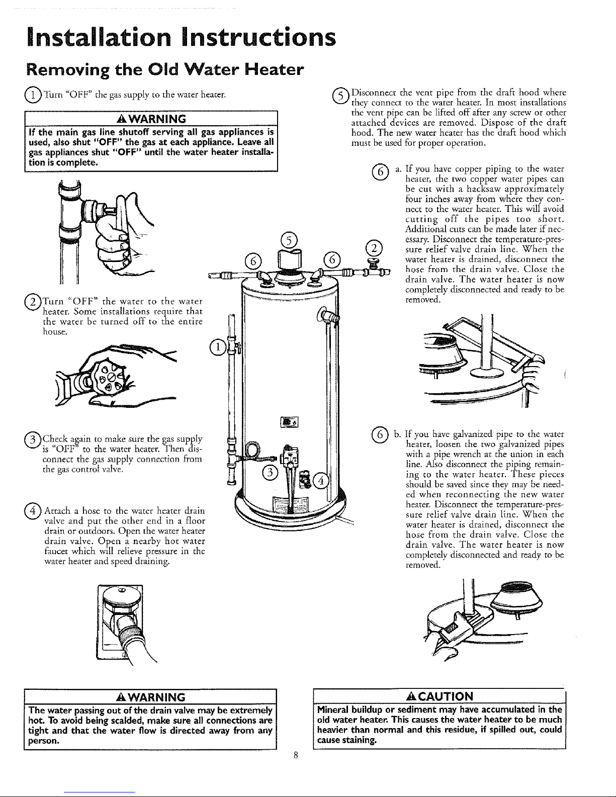
Installation Instructions
Removing the Old Water Heater
Turn "OFF" the gas supply to the water heater,
_WARNING
If the main gas line shutoff serving all gas appliancesis
used,also shut "OFF" the gasat each appliance.Leaveall
gasappliancesshut "OFF" until the water heater installa-
tion iscomplete.
Turn "OFF" the water to the water
heater, Some installations require that
the water be turned off to the entire
house.
('_Check again to make sure the gas supply
_Jis OFF to the water heater. Then dis- __
connect the gas supply connection from
the gas control valve, "
A
Attach a hose to the water heater drain
valve and put the other end in a floor
drain or outdoors. Open the water heater
drain valve. Open a nearby hot water
_ucet which will relieve pressure in the
water heater and speed draining.
Disconnect the vent pipe from the draft hood where
they connect to the water heater. In most installations
the vent pipe can be lifted off after any screw or other
attached devices are removed. Dispose of the draft
hood. The new water heater has the draft hood which
must be used for proper operation.
a.
If you have copper piping to the water
heater, the two copper water pipes can
be cut with a hacksaw approximately
four inches away from where they con-
nect to the water heater, This will avoid
cutting off the pipes too short.
Additional cuts can be made later if nec-
essary. Disconnect the temperature-pres_
sure retief valve drain line. When the
water heater is drained, disconnect the
hose from the drain valve. Close the
drain valve, The water beater is now
completely disconnected and ready to be
removed.
b,
If you have galvanized pipe to the water
heater, loosen the two galvanized pipes
with a pipe wrench at the union in each
line. Also disconnect the piping remain-
ing to the water heater. These pieces
should be saved since they may be need-
ed when reconnecting the new water
heater. Disconnect the temperature_pres-
sure relief valve drain line. When the
water heater is drained, disconnect the
hose from the drain valve. Close the
drain valve. The water heater is now
completely disconnected and readym be
removed.
AWARNING I
The water passingout of the drainvalvemay beextremely I
hot. To avoid beingscalded,make sure all connectionsare
tight and that the water flow is directed away from any
person.
_CAUTION I
Mineral buildup or sedimentmay have accumulatedin the I
oldwater heater.Thiscausesthe water heater to be much !
heavierthan normal and this residue, if spilledout, could
causestaining.
Installation Instructions (cont'd)
--acts to Consider About the
Location
You should carefully choose an indoor location for the new
water heater, because the placement is a very important consid-
eration _br the safety of the occupants in the building and for
the most economical use of the appliance. This water heater is
not for use in mobile homes or outdoor installation.
Whether replacing an old water heater or putting the water
heater in a new location, the following critical points must be
observed.
o The location selected should be indoors as c!ose as practical to
the gas vent or chimney to which the water heater vent is
going to be connected, and as centralized with the water pip-
ing system as possible. The water heater, as all water heaters,
will eventually leak. Do not install without adequate drainage
provisionswhere water flow will cause damage.
ACAUTION
WATER HEATERS EVENTUALLY LEAK: Installation of the
water heater must be accomplished in such a manner that if
the tank or any connections shouldleak, the flow of water will
not cause damage to the structure. When such locations can.
not be avoided, a suitable drain pan should be installed under
the water heater. Drain pans are available at your local Sears
store. Such a drain pan must be not greater than 1½ inches
deep, have a minimum length and width of at least 2 inches
greater than the water heater dimensions and must be piped
to an adequate drain. The pan must not restrict combustion air
flow. Under no circumstances isthe manufacturer or Searsto
be held liable for any water damage in connection with this
water heater.
AWARNING
INSTALLATIONS IN AREAS WHERE FLAHHABLE LIQUIDS
(VAPORS) ARE LIKELY TO BE PRESENT OR STORED
(GARAGES, STORAGE, AND UTILITY AREAS, ETC):
Flammable liquids(such as gasoline, solvents,propane (LP) or
butane, etc.), all of which emit flammable vapors, may be
improperly stored or used in such areas. The gaswater heater
pilot light or main burner can ignite suchvapors. The resulting
flashbackand fire can causedeath or seriousburns to anyone in
the area, aswell asproperty damage.
If installation in suchareasis your only option, then the installa-
tion must be accomplished in a way that the pilot flame and
main burner flame are elevated from the floor at least 18inches.
While this may reduce the chancesof flammable vapors from a
floor spillbeing ignited,gasolineand other flammable substances
shouldnever be stored or used in the same room or area con-
raining a gaswater heater or other open flame or spark produc-
ingappliance.
NOTE: Flammable vapors may be drawn by air currents from
other areasof the structure to the appliance.
[ AWARNING
Propellants of aerosol sprays and volatile compounds, (clean-
ers, chlorine based chemicals, refrigerants, etc.) in addition to
being highly flammable in many cases, will also change to cor-
rosive hydrochloric acid when exposed to the combustion
products of the water heater. The results can be hazardous,
and also causeproduct failure.
• The location selection must provide adequate clearances for ser-
vicing and proper operation of the water heater.
AWARNING
This water heater must not be installeddirectly on carpeting.
Carpeting must be protected by a metal or wood panel
beneath the appliance extending beyond the full width and
depth of the appliance by at least 3 inches (76.2mm) in any
direction, or if the appliance is installed in an alcove or closet,
the entire floor must be covered by the panel. Failure to heed
this warning may result ina fire hazard.
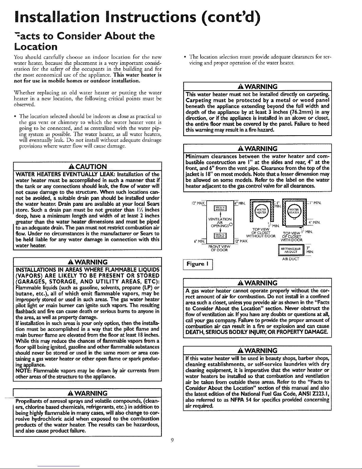
AWARNING
Minlmum clearances between the water heater and com-
bustible construction are I" at the sides and rear, 4" at the
front, and 6" from the vent pipe. Clearance from the top of the
jacket is 18" on most models. Note that a lesserdimension may
be allowed on some models. Refer to the label on the water
heater adjacent to the gascontrol valve for all clearances.
f2" MAX.
f
VENTILATION
AIR
OPENINGS O
6'_MI_--
FRONT VI _
OF DOOR
I Figure I
'11,MIN. _]_=_L] 4' HtN"
TOP VIEW
OF CLOSET TOP VIEW I" HIN,
WITHOUT DOOR OF CLOSET
_;' HAX, WITH DOOR
A_R DUCT
AWARNING
A gaswater heater cannot operate properly without the cor-
rect amount of air for combustion. Do not install in a confined
area sucha closet, unlessyou provide air asshown inthe "Facts
to Consider About the Location" section. Never obstruct the
flow of ventilation air. If you have any doubts or questionsat all,
call your gascompany. Failure to providethe proper amount of
combustion air can result in a fire or explosion and can cause
DEATH, SERIOUS BODILY INJURY,OR PROPERTY DAHAGE.
AWARNING
If this water heater will be usedin beauty shops,barber shops,
cleaning establishments, or self-service laundries with dry
cleaning equipment, it is imperative that the water heater or
water heaters be installed sothat combustion and ventilation
air be taken from outside these areas. Refer to the "Facts to
Consider About the Location" section ofthis manual and also
the latest edition of the National Fuel Gas Code, ANSI Z223.1,
also referred to as NFPA 54 for specificsprovided concerning
air required, i
Installation Instructions (cont'd)
Combustion Air and Ventilation
for Appliances Located in
Unconfined Spaces
Unconfined Space is a space whose volume is not less than 50
cubic feet per 1,000 Btu per hour of the aggregate input rating
of all appliances installed in that space. Rooms communicating
directly with the space in which the appliances are installed,
through openings not furnished with doors, are considered a
part of the unconfined space
In unconfined spaces in buildings, infiltration may be adequate
to provide air for combustion, ventilation and dilution of flue
gases. However, in buildings of tight construction (for example,
weather stripping, heavily insulated, caulked, vapor barrier, etc.),
additional air may need to be provided using the methods
described in Combustion Air and Ventilation for Appliances
Located in Confined Spaces, b.
Combustion Air and Ventilation
for Appliances Located in
Confined Spaces
Confined Space is a space whose volume is less than 50 cubic
feet per 1,000 Btu per hour of the aggregate input rating of all
appliances installed in that space.
a. ALL AIR FROM INSIDE BUILDINGS:
(See Page 8 Figure 1, and Figure 2 below)
The confined space shall be provided with two permanent
openings communicating directly with an additional room(s)
of sufficient volume so that the combined volume of all
spaces meets the criteria for an unconfined space. The total
input of all gas utilization equipment installed in the com-
bined space shall be considered in making this determination.
Each opening shall have a minimum flee area of one square
inch per 1,000 BTU per hour of the total input rating of all
gas utilization equipment in the confined space, but not less
than 100 square inches. One opening shall commence within
12 inches of the top nod one commencing within 12 inches
of the bottom of the enclosure.
I Figure 2 I
8 VENT
F_RNAC.E OPENINGS
Ill i _ _
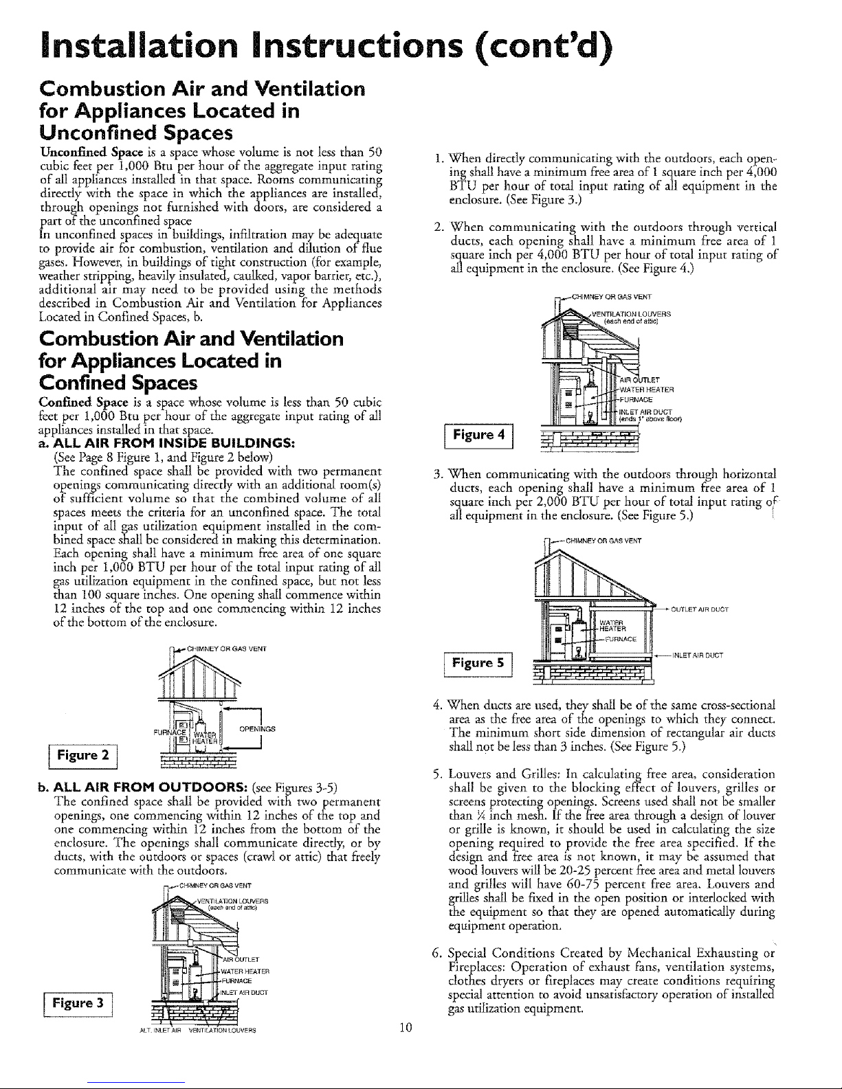
b. ALL AIR FROM OUTDOORS: (seeFigures 3-5)
The confined space shall be provided with two permanent
openings, one commencing within 12 inches of the top and
one commencing within 12 inches f?om the bottom of the
enclosure. The openings shall communicate directly, or by
ducts, with the outdoors or spaces (crawl or attic) that freely
communicate with the outdoors.
CHIMR_ OR GAg V_NT
VENTILATION LOUVER8
J_LT INLETAIN VENTILATIONLOHVENS
1. When directly communicating with the outdoors, each open-
ing shall have a minimum free area of 1 square inch per 4,000
BTU per hour of total input rating of all equipment in the
enclosure. (See Figure 3.)
2. When communicating with the outdoors through vertical
ducts, each opening shall have a minimum free area of 1
square inch per 4,000 BTU per hour of total input rating of
all equipment in the enclosure. (See Figure 4.)
Figure 4 ]
CHIMNEY OFt _AS VENT
VENTILATION LOUVERS
(eachend o_a_tic)
TLET
WATER HEATE FI
FUFtN,a.CE
INLET AJR DLFCT
a_ov_ floor_
3. When communicating with the outdoors through horizontal
ducts, each opening shall have a minimum free area of !
square inch per 2,000 BTU per hour of total input rat ng oF
all equipment in the enclosure. (See Figure 5.)
Figure 5 ]
_ GHIMNEY Ofl GAS VE I
WATFFI _ OUTLET AIF_ DUCT
%'&
_ INLET A_F_DUCT
4. \Vhen ducts are used, they shall be of the same cross-sectional
area as the free area of the openings to which they connect.
The minimum short side dimension of rectangular air ducts
shall not be lessthan 3 inches. (See Figure 5.)
10
,
.
Louvers and Grilles: In calculating free area, consideration
shall be given to the blocking effect of louvers, grilles or
screens protecting openings. Screens used shall not be smaller
than 5_inch mesh. If the f?ee area through a design of louver
or grille is known, it should be used in calculating the size
opening required to provide the free area specified. If the
design and free area is not lmown, it may be assumed that
wood louvers wil! be 20-25 percent free area and metal louvers
and grilles will have 60-75 percent free area. Louvers and
grilles shall be fixed in the open position or interlocked with
the equipment so that they are opened automatically during
equipment operation.
Special Conditions Created by Mechanical Exhausting or
Fireplaces: Operation of exhaust fans, ventilation systems,
clothes dryers or fireplaces may create conditions requiring
special attention to avoid unsatisfactory operation of installed
gas utilization equipment.
 Loading...