

Sears 149.23632,Craftsman 149.236320 Owner's Manual
owners
manual
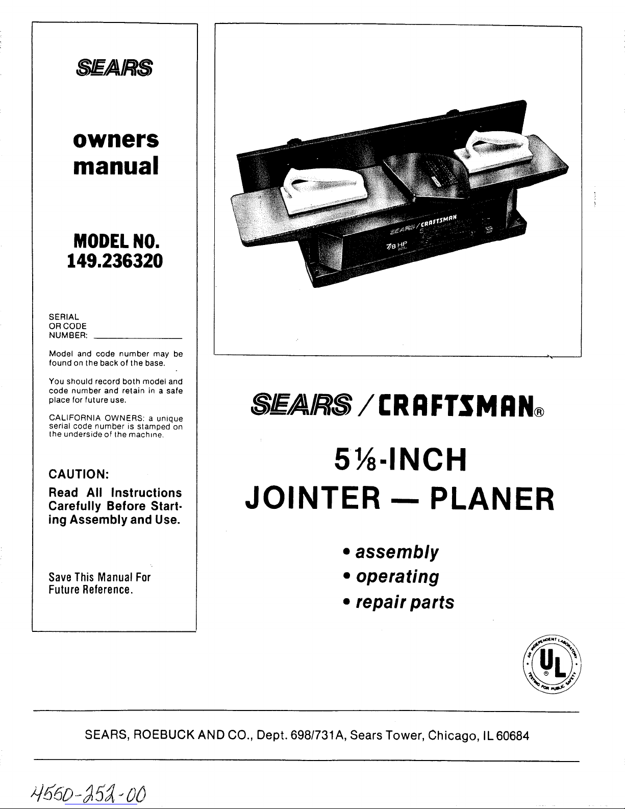
MODELNO.
149.236320
SERIAL
OR CODE
NUMBER:
Model and code number may be
found on the back of the base.
You should record both model and
code number and retain in a safe
place for future use.
CALIFORNIA OWNERS: a unique
serial code number is stamped on
the underside of the machine.
SWAIRS / r.RRFTSMRN®
CAUTION:
Read All Instructions
Carefully Before Start-
ing Assembly and Use.
Save This Manual For
FutureReference.
SEARS, ROEBUCK AN D CO., Dept. 698/731A, Sears Tower, Ch icago, IL 60684
51_.INCH
JOINTER-- PLANER
• assembly
• operating
• repair parts
d_o-15A- oo
FULL ONE-YEAR WARRANTY ON £RRFTSMRN, JOINTER -- PLANER
If within one year from the date of purchase, this Craftsman Jointer -- Planer fails due to a defect
in material or workmanship, Sears will repair it, free of charge.
WARRANTY SERVICE IS AVAILABLE BY CONTACTING THE NEAREST SEARS STORE OR SERVICE
CENTER IN THE UNITED STATES.
This warranty gives you specific legal rights and you may also have other rights which vary from
state to state.
Sears, Roebuck and Co. Dept. 698/731A, Sears Tower, Chicago, IL 60684.
GENERAL SAFETY RULES FOR POWER TOOLS
1. KNOW YOUR POWER TOOL
For your own safety, read the owner's manual carefully.
Learn its application and limitations as well as the specific
hazards peculiar to this tool.
2. GROUNDING INSTRUCTIONS
A. All grounded, cord-connected tools:
In the event of a malfunction or breakdown, grounding pro-
vides a path of least resistance for electric current to reduce
the risk of electric shock. This tool is equipped with an
electric cord having an equipment-grounding conductor and
a grounding plug. The plug must be plugged into a matching
outlet that is properly installed and grounded in accordance
with all local codes and ordinances.
Do not modify the plug provided - if it will not fit the outlet,
have the proper outlet installed by a qualified electrician.
Improper connection of the equipment-grounding conductor
can result in a risk of electric shock. The conductor with
insulation having an outer surface that is green with or with-
out yellow stripes is the equipment-grounding conductor. If
repair or replacement of the electric cord or plug is necessary,
do not connect the equipment-grounding conductor to a live
terminal.
Check with a qualified electrician or serviceman if the
grounding instructions are not completely understood, or if
in doubt as to whether the tool is properly grounded.
The use of any Extension Cord will cause some loss of power.
To keep this to a minimum and to prevent overheating and
motor burn-out, use the table below to determine the MINI-
MUM wire size (A.W.G.) Extension Cord.
Use only 3-wire extension cords that have 3-prong grounding
plugs, and 3-pole receptacles that accept the tool's plug.
Extension Cord Length Wire Size, A.W.G.
25 Feet 16
50 Feet 16
100 Feet 14
Extension Cords suitable for use with your Jointer-Planer are
available at your nearest Sears Catalog Order or Retail Store.
Repair or replace damaged or worn cord immediately.
B. Grounded, cord-connected tools intended for use on a
supply circuit having a nominal rating less than 150 volts:
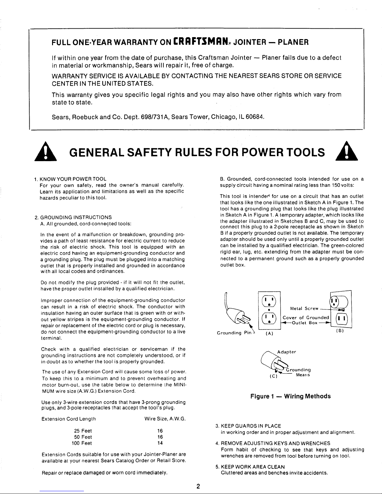
This tool is intended for use on a circuit that has an outlet
that looks like the one illustrated in Sketch A in Figure 1. The
tool has a grounding plug that looks like the plug illustrated
in Sketch A in Figure 1. A temporary adapter, which looks like
the adapter illustrated in Sketches B and C, may be used to
connect this plug to a 2-pole receptacle as shown in Sketch
B if a properly grounded outlet is not available. The temporary
adapter should be used only until a properly grounded outlet
can be installed by a qualified electrician. The green-colored
rigid ear, lug, etc. extendirig from the adapter must be con-
nected to a permanent ground such as a properly grounded
outlet box.
_ _ Meta=Screw
I ( I , ) t Cover of Grounded I (I I / I
____Out,et Box---_
Grounding Pin (A) (B)
Adapter
(G) Means
g
Figure I m Wiring Methods
3. KEEP GUARDS IN PLACE
in working order and in proper adjustment and alignment.
4. REMOVE ADJUSTING KEYS AND WRENCHES
Form habit of checking to see that keys and adjusting
wrenches are removed from tool before turning on tool.
5. KEEP WORK AREA CLEAN
Cluttered areas and benches invite accidents.
6.DON'TUSEINDANGEROUSENVIRONMENT
Don'tusepowertoolsindamporwetlocations,orexpose
themtorain.Keepworkareawellillumina'ced.
7.KEEPCHILDRENAWAY
Allvisitorsshouldbekeptasafedistancefromworkarea.
8.MAKEWORKSHOPKIDPROOF
withpadlocks,masterswitches,orbyremovingstarterkeys.
9.DON'TFORCETOOL
Itwilldothejobbetterandbesaferattherateforwhichit
wasdesigned.
10.USERIGHTTOOL
Don'tforcetoolor'attachmenttodoajobforwhichitwasnot
designed.
11.WEARPROPERAPPAREL
Nolooseclothing,gloves,neckties,rings,bracelets,or
jewelrytogetcaughtinmovingparts.Nonslipfootwearis
recommended.Wearprotectivehaircoveringtocontainlong
hair.
12.ALWAYSUSESAFETYGLASSES
Alsousefaceordustmaskif cuttingoperationisdusty.
Everydayeyeglassesonlyhaveimpactresistantlenses.They
areNOTsafetyglasses.
13.SECUREWORK
Useclampsoravisetoholdworkwhenpractical.It'ssafer
thanusingyourhandandfreesbothhandstooperatetool.
14.DON'TOVERREACH
Keepyourproperfootingandbalanceatalltimes.
15.MAINTAINTOOLSINTOPCONDITION
Keeptoolssharpandcleanforbestandsafestperformance.
Followinstructionsforlubricatingandchangingaccessories.
16.DISCONNECTTOOLSFROMPOWERSOURCE
beforeservicingandwhenchangingaccessoriessuchas
blades,bits.cutters,orwhenmountingandre-mounting
motor.
17.
18.
19.
20.
21.
22.
AVOIDACCIDENTALSTARTING
Makesureswitchisin"OFF"positionbeforepluggingin
cord.
USERECOMMENDEDACCESSORIES
Consulttheowner'smanualforrecommendedaccessories.
Useofimproperaccessoriesmaybehazardous.
NEVERSTANDONTOOL
Seriousinjurycouldoccurifthetoolistippedorifthecutting
toolisunintentionallycontacted.
CHECKDAMAGEDPARTS
Beforefurtheruseofthetool,aguardorotherpartthatis
damagedshouldbecarefullycheckedtoensurethatitwill
operateproperlyandperformitsintendedfunction-check
foralignmentof movingparts,bindingof movingparts,
breakageofparts,mounting,andanyotherconditionsthat
mayaffectitsoperation.Aguardorotherpartthatisdamaged
shouldbeproperlyrepairedorreplaced.
DIRECTIONOFFEED
Feedworkintoabladeorcutteragainstthedirectionof
rotationofthebladeorcutteronly.
NEVERLEAVETOOLRUNNINGUNATTENDED.TURN
POWEROFF.Don'tleavetooluntilitcomestoacomplete
stop.
Theoperationofanypowertoolcanresultinforeignobjects
beingthrownintotheeyes,whichcanresultinsevereeye
damage.AlwayswearsafetygogglescomplyingwithANSIZ87.1
(shownonPackage)beforecommencingpowertooloperation.
SafetyGogglesareavailableatSearsretailorcatalogstores.
TABLE OF CONTENTS
GENERAL SAFETY RULES FOR POWER TOOLS ............ 2, 3
UNPACKING AND CHECKING CONTENTS .................. 4
SAFETY RULES FOR JOINTER-PLANER ...................... 5
ASSEMBLY .......................................... 5-7
Depth of Cut Hand Knob .................................. 5
Chip Deflector ............................................ 5
Checking Cutter Blades ................................... 6
Fence .................................................. 6, 7
Fence Extension .......................................... 7
INSTALLING THE JOINTER-PLANER ......................... 8
CONTROLS AND ADJUSTMENTS ....................... 8-9
Depth of Cut Hand Knob ................................ 8, 9
Fence Adjustment ........................................ 9
Cutter Guard ............................................. 9
ON/OFF Switch ........................................... 9
BASIC JOINTER-PLANER OPERATION ................... 10-12
Feeding the Workpiece .................................. 10
Using Holddown/Push Blocks ............................ 11
Beveling, Chamfering ................................. 11, 12
Using a Wet/Dry Vac ..................................... 12
MAINTENANCE ........................................ 12, 13
Timing Belt Replacement ................................ 12
Cutter Guard Return Spring .............................. 12
Blade Replacement and Adjustment ...................... 13
General Maintenance .................................... 13
REPAIR PARTS ......................................... 14, 15
TROUBLE SHOOTING ...................................... 16
How to Order Replacement Parts ......................... 16
UNPACKING AND CHECKING CONTENTS
Model 149.236320 Jointer-Planer is shipped complete in one
carton.
Separate all parts from packing materials and check each one
with the illustration and the list of loose parts to make certain
all items are accounted for, before discarding any packing
material.
If any parts are missing, do not attempt to assemble the
jointer-planer, plug in the power cord or turn the switch on
until the missing parts are obtained and are installed correctly.
Wipe all parts thoroughly with a clean, dry cloth.
Apply a coat of clear automobile paste wax to the tables.
,_WARNING: FOR YOUR OWN SAFETY, NEVER CON-
NECT TO POWER SOURCE UNTIL ALL ASSEMBLY
STEPS ARE COMPLETE, AND YOU HAVE READ AND
UNDERSTAND THE SAFETY AND OPERATIONAL INSTRUC-
TIONS.
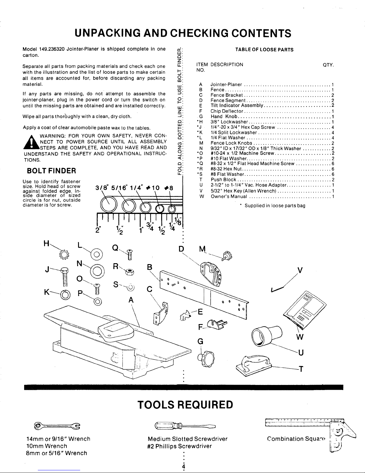
BOLT FINDER
Use to identify fastener
size. Hold head of screw
against folded edge. In-
side diameter of sized
circle is for nut, outside
diameter is for screw.
318' 5/16" 114" ÷10 ÷8
LU.
Z.
I.
LL.
F-'
O.
,-n:
LU:
Cf)"
o:
uJ:
z:
a:
I._.
O.
a:
2::
a:
-J.
O'
TABLE OF LOOSE PARTS
ITEM DESCRIPTION QTY.
NO.
A Jointer-Planer ..................................... 1
B Fence ............................................. 1
C Fence Bracket ..................................... 2
D Fence Segment .................................... 2
E Tilt Indicator Assembly .......................... 2
F Chip Deflector ..................................... 1
G Hand Knob .................................... 1
*H 318" Lockwasher ................................... 1
*J 1/4"-20 x 314" Hex Cap Screw ....................... 4
*K 1/4 Split Lockwasher ............................... 4
*L 1/4 Flat Washer .................................... 4
M Fence Lock Knobs ................................. 2
N 9132"lDx1_7132"ODx118"ThickWasher ............ 2
*O #10-24 x 1/2 Machine Screw ...................... 2
*P #10 Flat Washer .................................... 2
*Q #8-32 x 112" Flat Head Machine Screw ............... 6
*R #8-32 Hex Nut ....................................... 6
*S #8 Flat Washer ..................................... 6
T Push Block ........................................ 2
U 2-1/2" to 1-1/4" Vac. Hose Adapter ................... 1
V 5/32" Hex Key (Allen Wrench) ....................... 1
W Owner's Manual ................................... 1
* Supplied in loose parts bag
1/2" 1/_'4
B
\
\
C
\
\
D
M
G
14mm or 9/16" Wrench
10mm Wrench
8mm or 5/16" Wrench
TOOLS REQUIRED
_.......3
Medium Slotted Screwdriver
#2 Phillips Screwdriver
Combination Squa,-e i L'_
SAFETY RULES FOR JOINTER--PLANER
Safety is a combination of operator common sense and alertness at all times when the Jointer--Planer is being
used. Study these rules and general safety rules before operating and retain them for future use.
1. WEAR EYE PROTECTION.
2. NEVER MAKE JOINTING OR PLANING CUT DEEPER THAN
1/8 INCH -- PER PASS.
3. FEED WORKPIECE AGAINST ROTATION OF CUTTER.
4. KEEP FINGERS AWAY FROM REVOLVING CUTTER -- use
fixtures when necessary.
5. NEVER PERFORM JOINTING OR PLANING OPERATION
WITH CUTTER HEAD GUARD REMOVED.
6. NEVER FORCE CUTTING ACTION. Stalling or partial stalling
of motor can cause major damage. Allow motor to reach full
speed before cutting.
7. NEVER - Attempt to perform an abnormal or little used
operation without study and the use of adequate hold down
/push blocks, jigs, fixtures, stops, etc.
8. NEVER - Attempt to cut small pieces.
9.
ALWAYS - Use hold down/push blocks for jointing material
narrower than 3 inches, or planing material thinner than 3
inches.
10.
ALWAYS- Keep cutter sharp.
11.
NEVER- Use in an explosive atmosphere. Normal sparking of
motor may ignite fumes.
12.
OUTDOOR EXTENSION CORD USE - When tool is used
outdoors, use only extension cords suitable for use outdoors.
Outdoor approved cords are marked with the sL'ffix W-A, for
example- SJTW-A or SJOW-A.
13. ALWAYS use identical replacement parts when servicing.
14.This tool is intended for RESIDENTIAL USE ONLY.
WARNING: DO NOT ALLOW FAMILIARITY (GAINED FROM
FREQUENT USE OF YOUR JOINTER--PLANER) TO BECOME
COMMONPLACE. ALWAYS REMEMBER THAT A CARELESS
FRACTION OF A SECOND IS SUFFICIENT TO INFLICT SEVERE
INJURY.
WARNING: DO NOT AT ANY TIME LET BRAKE FLUIDS, GASOLINE, PENETRATING OILS, ETC.
,_ CONTACT WITH PLASTIC PARTS. THEY CONTAIN CHEMICALS THAT CAN DAMAGE
COME IN
AND/OR DESTROY PLASTICS.
ASSEMBLY
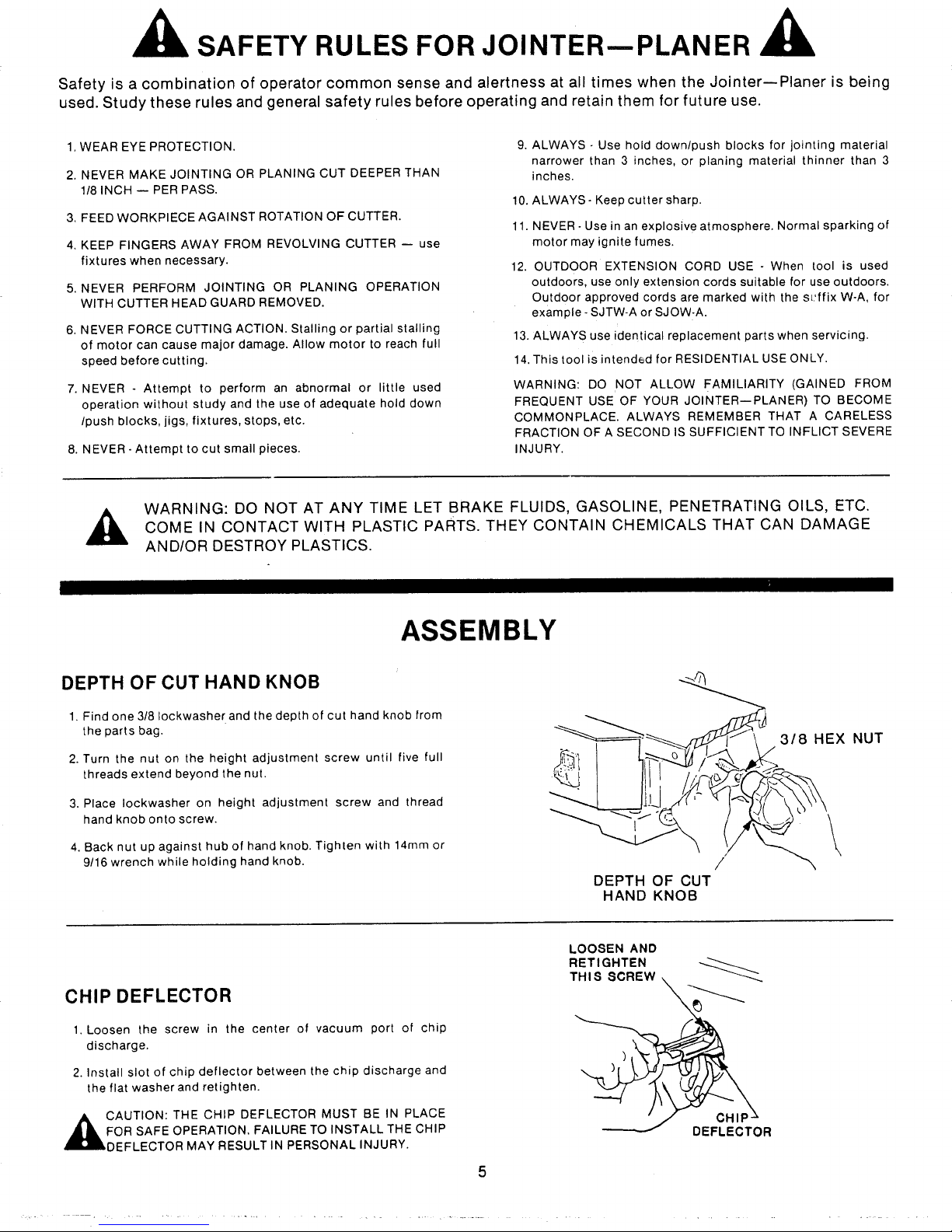
DEPTH OF CUT HAND KNOB
1. Find one 3/8 lockwasher and the depth of cut hand knob from
the parts bag.
2. Turn the nut on the height adjustment screw until five full
threads extend beyond the nut.
3. Place Iockwasher on height adjustment screw and thread
hand knob onto screw.
4. Back nut up against hub of hand knob. Tighten with 14ram or
9/16 wrench while holding hand knob. t
DEPTH OF CUT
HAND KNOB
LOOSEN AND
RETIGHTEN
CHIP DEFLECTOR
1. Loosen the screw in the center of vacuum port of chip
discharge.
2. Install slot of chip deflector between the chip discharge and
the flat washer and retighten.
T H I S SCREW _..........._.
3/8 HEX NUT
,_CAUTION: THE CHIP DEFLECTOR MUST BE IN PLACE
FOR SAFE OPERATION. FAILURE TO INSTALL THE CHIP
DEFLECTOR MAY RESULT IN PERSONAL INJURY.
DEFLECTOR
 Loading...