

Page 1
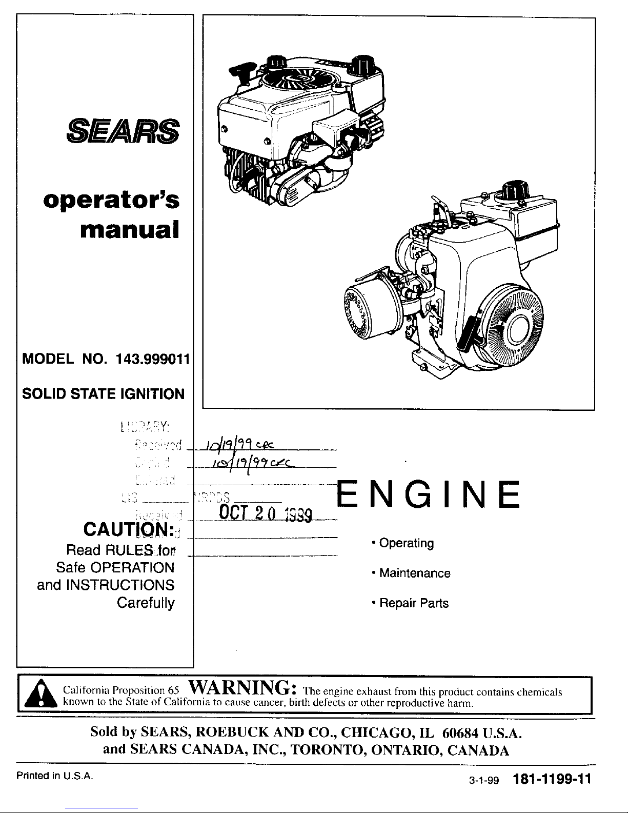
SEARS
operator's
manual
MODEL NO. 143.999011
SOLID STATE IGNITION
[ y, -!:-,_y:
. d
Li3 ........
CAUT!ON:_
Read RULES.fo_
Safe OPERATION
and INSTRUCTIONS
Carefully
_,q_'_l'_
___j._c=..__
ENGIN
OCT2o "°L..... !_Q
• Operating
• Maintenance
• Repair Parts
California Proposition 65 WARNING: The engine exhaust from this product contains chemicals I
known to the State of California to cause cancer, birth defects or other reproductive harm.
I
Sold by SEARS, ROEBUCK AND CO., CHICAGO, IL 60684 U.S.A.
and SEARS CANADA, INC., TORONTO, ONTARIO, CANADA
Printed in U.S.A. 3-1-99 181-1199-11
Page 2
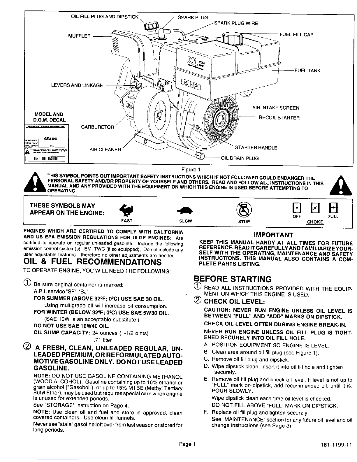
OIL FILL PLUG AND DIPSTICK SPARK PLUG
\ WIRE
FUEL FILL CAP
LEVERS AND LINKAGE
]REEN
MODEL AND
D.O.M. DECAL
AIR CLEANER
STARTER HANDLE
PLUG
,_ THIS SYMBOL POINTS OUT IMPORTANT SAFETY INSTRUCTIONS WHICH IF NOT FOLLOWED COULD ENDANGER THE
PERSONALSAFETY AND/OR PROPERTY OF YOURSELFAND OTHERS. READ AND FOLLOW ALL INSTRUCTIONS IN THIS
MANUALAND ANY PROVIDED WITH THE EQUIPMENT ON WHICH THIS ENGINE IS USED BEFORE AI-rEMPTING TO
OPERATING,
APPEAR ON THE ENGINE:
FAST SLOW STOP
ENGINES WHICH ARE CERTIFIED TO COMPLY WITH CALIFORNIA
AND US EPA EMfSSfON REGDLAT|ONS FOR ULGE ENGINES: Are
certifiedto operate on regular unleaded gasoline Include the following
emission control system(s): EM, TWC (if so equipped); Do not include any
user adiustable features - therefore no other adjustmentsare needed.
OIL & FUEL RECOMMENDATIONS
TO OPERATE ENGINE, YOU WILL NEED THE FOLLOWING:
Figure 1
A
(_) Be sure original container is marked:
A.P.I. service "SF"-"SJ".
FOR SUMMER (ABOVE 32°F; 0°C) USE SAE 30 OIL.
Using multigrade oil will increase oil consumption.
FOR WINTER (BELOW 32°F; 0°C) USE SAE 5W30 OIL.
(SAE 10W is an acceptable substitute.)
DO NOT USE SAE 10W40 OIL.
OIL SUMP CAPACITY: 24 ounces (1-1/2 pints)
.71 liter
(_) A FRESH, CLEAN, UNLEADED REGULAR, UN-
LEADED PREMIUM, OR REFORMULATED AUTO-
MOTIVE GASOLINE ONLY. DO NOT USE LEADED
GASOLINE.
NOTE: DO NOT USE GASOLINE CONTAINING METHANOL
(WOOD ALCOHOL). Gasoline containing up to 10% ethanol or
grain alcohol ("Gasohol"), or up to 15% MTBE (Methyl Tertiary
Butyl Ether), may be used but requires special care when engine
is unused for extended periods.
See "STORAGE" instruction on Page 4.
NOTE: Use clean oil and fuel and store in approved, clean
covered containers. Use clean fill funnels.
Never use "stale" gasoline left over from last season orstored for
long periods.
E! FI FI
OFF FULL
CHOKE
q
IMPORTANT
KEEP THIS MANUAL HANDY AT ALL TIMES FOR FUTURE
REFERENCE. READ IT CAREFULLY AND FAMILIARIZE YOUR-
SELF WITH THE OPERATING, MAINTENANCE AND SAFETY
INSTRUCTIONS. THIS MANUAL ALSO CONTAINS A COM-
PLETE PARTS LISTING.
BEFORE STARTING
1_ READ ALL INSTRUCTIONS PROVIDED WITH THE EQUIP-
MENT ON WHICH THIS ENGINE IS USED.
(_) CHECK OIL LEVEL:
CAUTION: NEVER RUN ENGINE UNLESS OIL LEVEL IS
BETWEEN "FULL" AND "ADO" MARKS ON DIPSTICK.
CHECK OIL LEVEL OFTEN DURING ENGINE BREAK-IN.
NEVER RUN ENGINE UNLESS OIL FILL PLUG IS TIGHT-
ENED SECURELY INTO OIL FILL HOLE.
A. POSITION EQUIPMENT SO ENGINE IS LEVEL.
B. Clean area around oil fill plug (see Figure 1).
C. Remove oil fill plug and dipstick.
D. Wipe dipstick clean, insert it into oil fill hole and tighten
securely.
E. Remove oil fill plug and check oil level. If level is not up to
"FULL" mark on dipstick, add recommended oil, until it is.
POUR SLOWLY.
Wipe dipstick clean each time oil level is checked.
DO NOT FILL ABOVE "FULL" MARK ON DIPSTICK.
F. Replace oil fill plug and tighten securely.
See "MAINTENANCE" section for any future oil level and oil
change instructions (see Page 3).
Page 1 181-1199-11
Page 3
BEFORE STARTING (Continued)
STARTING
_) FILL FUEL TANK with gasoline as specified in the preced-
ing "OIL & FUEL RECOMMENDATIONS item 2.
|
NEVER MIX OIL WITH GASOLINE
Never use "stale" gasoline left over from last season or stored for
long periods.
,_NEVER FILL FUEL TANK INDOORS. NEVER FILL FUEL
TANK WHEN ENGINE IS RUNNING OR HOT. DO NOT SMOKE
W___N__ILLING FUEL TANK,
ANk NEVER FILL FUEL TANK COMPLETELY. FILL TANK TO 1/2"
BELOW BOTTOM OF FILLER NECK TO PROVIDE SPACE
FOR FUEL EXPANSION. WIPE ANY FUEL SPILLAGE FROM O
ENGINE AND EQUIPMENT BEFORE STARTING ENGINE.
_1 ANY LIQUEFIED PETROLEUM (LPG) OR NATURAL GAS 1
FUEL SYSTEM MUST BE LEAKPROOF AND MEET ALL
APPLICABLE CODES AND REGULAT ONS.
NEVER RUN ENGINE INDOORS OR IN ENCLOSED, POORLY
VENTILATED AREAS. ENGINE EXHAUST CONTAINS CAR-
BON MONOXIDE, AN ODORLESS AND DEADLY GAS (CAR-
BON MONOXIDE IS ALSO PRESENT IN ENGINE EXHAUST
FROM LIQUID PETROLEUM (LPG) AND NATURAL GAS
FUEL SYSTEMS).
_KEEP HANDS, FEET, HAIR AND LOOSE CLOTHING AWAY
FROM ANY MOVING PARTS _ONENGINE AND EQUIPMENT.
,_ WARNING: TEMPERATURE OF MUFFLER AND NEARBY
AREAS MAY EXCEED 150°F (65°C). AVOID THESE AREAS.
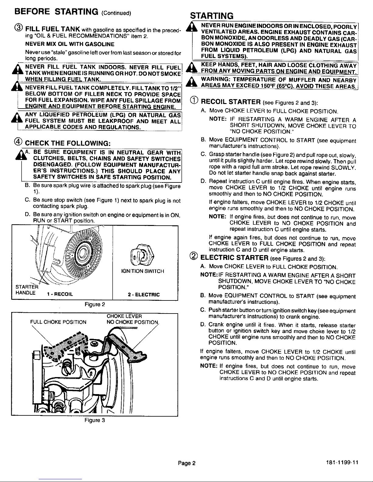
RECOIL STARTER (see Figures 2 and 3):
A. Move CHOKE LEVER to FULL CHOKE POSITION.
NOTE: IF RESTARTING A WARM ENGINE AFTER A
SHORT SHUTDOWN, MOVE CHOKE LEVER TO
"NO CHOKE POSITION."
(_ CHECK THE FOLLOWING:
_1_ BE SURE EQUIPMENT IS IN NEUTRAL GEAR WITH 1
CLUTCHES, BELTS, CHAINS AND SAFETY SWITCHES /
DISENGAGED. (FOLLOW EQUIPMENT MANUFACTUR- /
ER'S INSTRUCTIONS.) THIS SHOULD PLACE ANY /
SAFETY SWITCHES IN SAFE STARTING POSITION. J
B. Be sure spark plug wire is attached to spark plug (see Figure
1).
C, Be sure stop switch (see Figure 1) next to spark plug is not
contacting spark plug.
D. Be sure any ignition switch on engine or equipment is in ON,
BUN or START position.
STARTER
HANDLE
FULL CHOKE POSITION
\
IGNITION SWITCH
1 - RECOtL 2 - ELECTRIC
Figure 2
CHOKE LEVER
NO CHOKE
B. Move EQUIPMENT CONTROL to START (see equipment
manufacturer's instructions).
C. Grasp starter handle (see Figure 2) and pull rope out, slowly,
until it putts slightly harder. Let rope rewind slowly. Then pull
rope with e rapid full arm stroke. Let rope rewind SLOWLY.
Do not let starter handle snap back against starter.
D. Repeat instruction C until engine fires, When engine starts,
move CHOKE LEVER to 1/2 CHOKE until engine runs
smoothly and then to NO CHOKE POSITION.
If engine falters, move CHOKE LEVER to 1/2 CHOKE until
engine runs smoothly and then to NO CHOKE POSITION.
NOTE: If engine fires, but does not continue to run, move
CHOKE LEVER to NO CHOKE POSITION and
repeat instruction C until engine starts.
If engine again fires, but does not continue to run, move
CHOKE LEVER to FULL CHOKE POSITION and repeat
instruction C and D until engine starts.
(_) ELECTRIC STARTER (see Figures 2 and 3):
A. Move CHOKE LEVER to FULL CHOKE POSITION.
NOTE:IF RESTARTING A WARM ENGINE AFTER A SHORT
SHUTDOWN, MOVE CHOKE LEVER TO =NO CHOKE
POSITION."
B. Move EQUIPMENT CONTROL to START (see equipment
manufacturer's instructions).
C. Push starter button or turn ignition switch key (see equipment
manufacturer's instructions) to crank engine.
D. Crank engine until it fires. When it starts, release starter
button or ignition switch key and move choke lever to 1/2
CHOKE until engine runs smoothly and then to NO CHOKE
POSITION.
If engine falters, move CHOKE LEVER to 1/2 CHOKE until
engine runs smoothly and then to NO CHOKE POSITION.
NOTE: If engine fires, but does not continue to run, move
CHOKE LEVER to NO CHOKE POSITION and repeat
instructions C and D until engine starts.
Figure 3
Page 2 181-1199-11
Page 4
STOPPING
(_) Move equipment control or any ignition stop switch on engine
to STOP or OFF (see equipment manufacturer's instructions).
(_) Push stop switch (see Figure 1) located next to spark plug on
engine against spark plug and hold it in this position untilengine
is completely stopped.
AFTER ENGINE IS STOPPED:
,_k.A. DISCONNECT SPARK PLUG WIRE FROM SPARK PLUG I
AND KEEP IT AWAY FROM SPARK PLUG. J
,_B. TURN IGNITION SWITCH KEY (IF SO EQUIPPED) TO I
"OFF" POSITION AND REMOVE KEY FROM SWITCH. I
l THIS WILL REDUCE THE POSSIBILITY OF UNAUTHO- I
RIZED STARTING OF ENGINE WHILE EQUIPMENT IS I
NOT IN USE. J
,_ NEVER STORE ENGINE WITH FUEL IN TANK INDOORS I
OR IN ENCLOSED, POORLY VENTILATED AREAS]
WHERE FUEL FUMES MAY REACH AN OPEN FLAME, I
SPARK OR PILOT LIGHT AS ON A FURNACE, WATER I
HEATER, CLOTHES DRYER OR OTHER GAS APPLI-I
ANCE. I
MAINTENANCE
._WARNING: TEMPERATURE OF MUFFLER AND NEARBY
AREAS MAY EXCEED 150°F (65°C). AVOID THESE AREAS.
1_ CHECK OIL LEVEL:
Check oil level every five (5) operating hours or each time engine
is used. See "2 CHECK OIL LEVEL" in "BEFORE STARTING"
on Page 1.
CHANGE OIL:
Change oil after first two (2) operating hours and every 25
operating hours thereafter, more often if operated in extremely
dusty or dirty conditions. Change oil while engine is still warm
from recent running.
A. Position equipment so engine oil drain plug is lowest point on
engine (see Figure 1).
B. Remove oil drain plug and oil fill plug to drain oil.
C. Replace oil drain plug and tighten securely.
D. Fill oil sump with recommended oil. See "OIL & FUEL
RECOMMENDATIONS" and "CHECK OIL LEVEL" on Page
1.
MAINTENANCE (Continued)
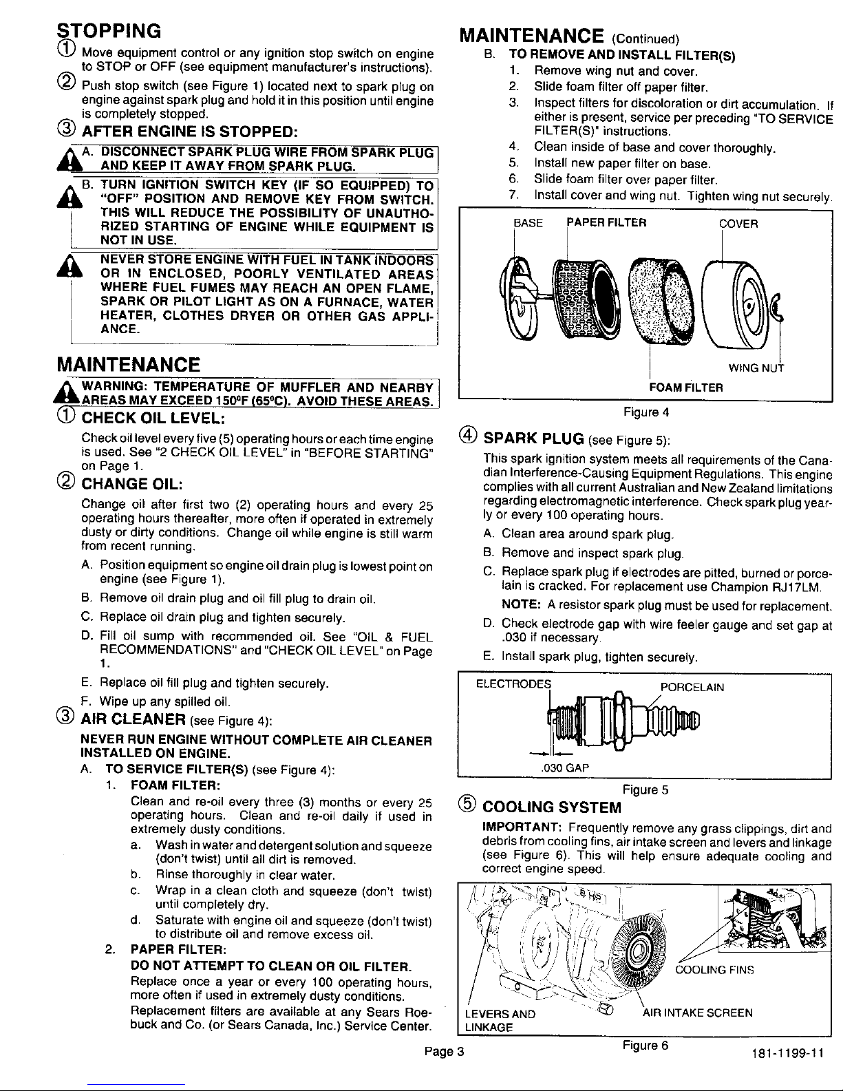
B. TO REMOVE AND INSTALL FILTER(S)
1. Remove wing nut and cover.
2. Slide foam filter off paper filter.
3. Inspect filters for discoloration or dirt accumulation. It
either is present, service per preceding "TO SERVICE
FILTER(S)" instructions.
4. Clean inside of base and cover thoroughly.
5. Install new paper filter on base.
6. Slide foam filter over paper filter.
7. Install cover and wing nut. Tighten wing nut securely.
BASE PAPER FILTER COVER
®
WING NUT
FOAM FILTER
Figure 4
SPARK PLUG (see Figure 5):
This spark ignition system meets all requirements of the Cana-
dian Interference-Causing Equipment Regulations. This engine
complies with all current Australian and New Zealand limitations
regarding electromagnetic interference. Check spark plug year-
ly or every 100 operating hours.
A. Clean area around spark plug.
B. Remove and inspect spark plug.
C. Replace spark plug if electrodes are pitted, burned or porce-
lain is cracked. For replacement use Champion RJ17LM
NOTE: A resistor spark plug must be used for replacement.
D. Check electrode gap with wire feeler gauge and set gap at
.030 if necessary.
E. Install spark plug, tighten securely.
E. Replace oil fill plug and tighten securely.
F. Wipe up any spilled oil.
(_) AIR CLEANER (see Figure 4):
NEVER RUN ENGINE WITHOUT COMPLETE AIR CLEANER
INSTALLED ON ENGINE.
A. TO SERVICE FILTER(S) (see Figure 4):
1. FOAM FILTER:
Clean and re-oil every three (3) months or every 25
operating hours. Clean and re-oil daily if used in
extremely dusty conditions.
a. Wash inwater and detergent solution and squeeze
(don't twist) until all dirt is removed.
b. Rinse thoroughly in clear water.
c. Wrap in a clean cloth and squeeze (don't twist)
until completely dry.
d. Saturate with engine oil and squeeze (don't twist)
to distribute oil and remove excess oil.
2. PAPER FILTER:
DO NOT ATTEMPT TO CLEAN OR OIL FILTER.
Replace once a year or every 100 operating hours,
more often if used in extremely dusty conditions.
Replacement filters are available at any Sears Roe-
buck and Co. (or Sears Canada, Inc.) Service Center.
ELECTRODES PORCELAIN
.030 GAP
Figure5
(_ COOLING SYSTEM
IMPORTANT: Frequently remove any grass clippings, dirt and
debris from cooling fins, air intake screen and levers and linkage
(see Figure 6). This will help ensure adequate cooling and
correct engine speed.
COOLING FINS
LEVERS AND
LINKAGE
AIR INTAKE SCREEN
Page 3 Figure 6 181-1199-11
Page 5

MAINTENANCE (Continued)
(_ CHECK ENGINE AND EQUIPMENT OFTEN FOR LOOSE I
NUTS, BOLTS AND ATTACHMENTS AND KEEP THESE
ITEMS TIGHTENED.
ADJUSTMENTS
DO NOT MAKE UNNECESSARY ADJUSTMENTS. FACTORY
SETTINGS ARE SATISFACTORY FOR MOST APPLICATIONS
AND CONDITIONS. iF ADJUSTMENTS ARE NEEDED, PRO-
CEED AS FOLLOWS:
(_ CARBURETOR (see Figure 7):
If you think your carburetor needs adjusting, see your nearest
SEARS, ROEBUCK AND CO. (OR SEARS CANADA, INC.)
SERVICE CENTER. Engine performance should not be af-
fected at altitudes up to 7,000 feet. For operation at higher
elevations, contact your nearest SEARS, ROEBUCK AND CO.
(OR SEARS CANADA, INC.) SERVICE CENTER.
(_ ENGINE SPEED:
_k NEVER TAMPER WITH ENGINE GOVERNOR WHICH IS FAC- ]
TORY SET FOR PROPER ENGINE SPEED. OVERSPEEDING
ENGINE ABOVE FACTORY HIGH SPEED SETTING CAN BE[
i DANGEROUS.
I CHANG NG OF ENGINE-GOVERNED SPEED WILL VOID
[ ENGINE WARRANTY. J
CARBURETOR.
\
BOWL DRAIN
Figure 7
STORAGE
,_ NEVER STORE ENGINE WITH FUEL IN TANK INDOORS OR
IN ENCLOSED, POORLY VENTILATED AREASWRERE FUEL
FUMES MAY REACH AN OPEN FLAME, SPARK OR PILOT
LIGHT AS ON A FURNACE, WATER HEATER, CLOTHES
DRYER OR OTHER GAS APPLIANCE.
IF ENGINE IS TO BE UNUSED FOR 30 DAYS FOR MORE, PRE-
PARE AS FOLLOWS:
(_ DRAIN FUEL SYSTEM:
Remove all gasoline from carburetor and fuel tank to prevent
gum deposits from forming on these parts and causing possible
malfunction of engine.
DRAIN FUEL INTO APPROVED CONTAINER OUTDOORS,]
AWAY FROM OPEN FLAME. BE SURE ENGINE IS COOL. DO /
NOT SMOKE.
Run engine until luel tank is empty and engine stops doe to lack
of fuel.
NOTE: Fuel stabilizer (such as STA-BIL) is an acceptable
alternative in minimizing the formation of fuel gum
deposits during storage. Add stabilizer to gasoline in
fuel tank or storage container. Always follow mix ratio
found on stabilizer container. Run engine at least 10
minutes after adding stabilizer to allow it to reach
carburetor.
_) CHANGE OIL:
Change oil if it has not been changed in the last three (3) months.
See "CHANGE OIL" instructions in" MAINTENANCE" section.
_) OIL CYLINDER BORE:
A. Remove spark plug and poor one (1) ounce (30 ml} of clean
engine oil into spark plug hole.
B. Cover spark plug hole with a rag.
C. Crank engine over, slowly, several times.
AVOID SPRAY FROM SPARK PLUG HOLE WHEN I
CRANKING ENGINE OVER SLOWLY. I
D. Install spark plug. Do not connect spark plug wire.
(_ CLEAN ENGINE:
Removeany clippings,dirt,or chaff fromexteriorof engine,
GENERAL
Just as your automobile needs professional mechanical mainte-
nance from time to time, so does your Craftsman engine. Replace-
ment of the spark plug and air cleaner is made necessary by
NORMAL use. Professional Air-Cooled Engine Service is as close as
your nearest Sears Roebuck and Co. (or Sears Canada, Inc.) Service
Center.
A yearly check-up or tune-up by Sears is a good idea to avoid
breakdowns or delay.., do it at the end of the season, then you're
ready for the next. We even prepare it for storage for you.
Page 4 181-1199-11
Page 6

TROUBLESHOOTING
THE FOLLOWING MAY HELP AVOID A DELAY IN YOUR WORK OR
SAVE THE EXPENSE OF A SERVICE CALL,
ENGINE FAILS TO START OR STARTS WITH DIFFICULTY
CAUSE
Controls not in start position.
Spark plug wire disconnected from sparkplug.
Sparkplug fouled.
Spark plug porcelain cracked.
Insufficient fuel.
Water or dirt in fuel.
Improper carburetor adjustment
ENGINE LACKS POWER
CAUSE
Dirty air cleaner.
Improper carburetor adjustment.
Lack of lubricaiton.
ENGINE MISSES UNDER LOAD
CAUSE
Spark plug fouled.
Spark plug porcelain cracked.
Improper spark plug gap.
improper carburetor adjustment
REMEDY
Move ENGINE CONTROL or equipment control to "HI" or
iSTART postion, See "STARTING" instructions in this
manual,
Connect SPARK PLUG WIRE to SPARK PLUG,
Remove SPARK PLUG and clean it, See "SPARK
PLUG" instructions in "MAINTENANCE" section in this
manual.
Install new spark plug,
Fill FUEL TANK per "BEFORE STARTING" instructions.
Drain FUEL TANK and re-fill with clean, fresh gasoline.
See "BEFORE STARTING" instructions in this manual.
Adjust carburetor (if applicable). See "ADJUSTMENTS"
section in this manual.
REMEDY
Replace or clean air cleaner per "AIR CLEANER"
instructions in "MAINTENANCE" section in this manual.
Adjust carburetor (if applicable). See "ADJUSTMENTS"
section in this manual.
Fill oil sump to proper level. See "BEFORE STARTING"
instructions section in this manual.
REMEDY
Remove SPARK PLUG and clean it. See "SPARK
PLUG" instructions in "MAINTENANCE" section in this
manual.
Install new SPARK PLUG.
Regap SPARK PLUG electrodes. See "SPARK PLUG"
instructions in "MAINTENANCE" section in this manual.
Adjust carburetor (if applicable). See "ADJUSTMENTS"
section in this manual.
Page 5 181-1199-11
Page 7

SEARS. ROEBUCK AND CO.
Federal and California Emission Control Systems Limited Warranty
Utility and Lawn and Garden Engines
CALIFORNIA & US EPA EMISSION CONTROL
WARRANTY STATEMENT
The U S. Environmental Protection Agency ("EPA'), the California Air Resources
Board ("CARB") and Sears, Roebuck and Co are pleased to exptain the Federal and
California Emission Control Systems Warranty on your new utility or lawn and
garden equipment engine In California, new 1995 and tater utility and lawn and
garden equipment engines must be designed, built and equippeO to meet the State's
stringent anti-smog standards, In other states, new 1997 and later model year
engines must be designed, built and equipped, at the time of sale, to meet the U.S
EPA regulations for small non-road engines Sears, Roebuck and Co. witl warrant
the emission control system on your utility or lawn and garden equ=pment engine for
the periods of time listed below, provided there has been no abuse, neglect,
unapproved modification, or =mproper maintenance of your utility or lawn and garden
equipment engine.
Your emission control system may include parts such as the carburetor, ignition
system and exhaust system Also included may be the compression release system
and other emission-related assemblies
Where a warrantable condition exists, Sears, Roebuck and Co. will repair your utility
or lawn and garden equipment engine at no cost to you for diagnosis, parts and
labor.
MANUFACTURER'S EMISSION CONTROL SYSTEM
WARRANTY COVERAGE
Emission control systems on 1995 and later model year California utility and lawn
and garden equipment engines are warranted for two years as hereinafter noted. In
other states, 1997 and later model year engines are also warranted for two years. If,
during such warranty period, any emission-related part on your engine is defective in
materials or workmanship, the part will be repaired or replaced by Sears, Roebuck
and Co.
OWNER'S WARRANTY RESPONSIBILITIES
AS the utility or lawn and garden equipment engine owner, you are responsible for
the performance of the required maintenance listed in your Owner's Manual, but
Sears, Roebuck and Co. will not deny warranty solely due to the lack of receipts or
for your failure to provide written evidence of the performance of all scheduled
maintenance.
AS the utility or lawn and garden equipment engine owner, you should, however, be
aware that Sears, Roebuck and CO may deny you warranty coverage if your utility or
lawn and garden equipment or a part thereof has failed due to abuse, neglect,
improper maintenance or unapproved modifications
You are responsible for presenting your utility or lawn and garden equipment engine
to a Sears, Roebuck and CO Authorized Service Outlet as soon as a problem exists.
The warranty repairs should be completed in a reasonable amount of time, not to
exceed 30 days
Warranty service can be arranged by contacting either a Sears, Roebuck and Co.
Authorized Service Outlet, or by contacting Sears, Roebuck and Co. at 1-800-473-
7247.
IMPORTANT NOTE
This warranty statement explains, y our dghts and obligations under the Emission
Control System Warranty ("ECS Warranty") which is provided to you by Sears,
Roebuck and Co pursuant to California taw. See also the Sears, Roebuck and Co,
Limited Warranties for Sears, Roebuck and Co which is enclosed therewith on a
separate sheet and also is provided to you by Sears, Roebuck and Co. The ECS
Warranty applies only to the emission control system of your new engine. To the
extent that there is any conflict in terms between the ECS Warranty and the Sears,
Roebuck and Co Warranty, the ECS Warranty shali apply except in any circum-
stances in which the Sears, Roebuck and Co Warranty may provide a longer
warranty period Both the ECS Warranty and the Sears, Roebuck and Co Warranty
describe important rights and obligations with respect to your new engine.
Warranty service can only be performed by a Sears, Roebuck and Co. Authorized
Service Outlet At the time of requesting warranty service, evidence must be
presented of the date of sale to the original purchaser The purchaser shatl pay any
charges for making service calls and/or for transporting the products to and from the
place where the inspection and/or warranty work is performed. The purchaser shall
be responsible for any damage or loss incurred in connection with the transportation
of any engine or any part(s) thereof submitted for inspection and/or warranty work.
II you have any questions regarding your warranty rights and responsibilities, you
should contact Sears, Roebuck and Co at 1-800-473-7247
EMISSION CONTROL SYSTEM WARRANTY
Emission Control System Warranty ("ECS Warranty") for 1995 and later model year
Cafifornia utility and lawn and garden equipment engines (for other states, 1997 and
later model year engines):
A APPLICABILITY: This warranty shall apply to 1995 and later model year
California utility and lawn and garden equipment engines (for other states, 1997 and
later model year engines) The ECS Warranty Period shall begin on the date the
new engine or equipment is delivered to its original, end-use purchaser, and shall
continue for 24 consecutive months thereafter
B, GENERAL EMISSIONS WARRANTY COVERAGE: Sears, Roebuck and Co
warrants to the original, end-use purchaser of the new engine or equipment and to
each subsequent purchaser that each of its utility and lawn and garden equipment
engines is:
1 Designed, bui8 and equipped so as to conform with all applicable regulations
adopted by the Air Resources Board pursuant to its authority in Chapters !
and 2, Part 5, Division 26 of the Health and Safety Code, and
2. Free from defects in materials and workmanship which, at any time during the
ECS Warranty Period, will cause a warranted emissions-related part to fail to
be identical in air material respects to the part as described in the engine
manufacturer's abplication for certification
C The ECS Warranty only pertains to emissions-related parts on your engine, as
fotlows:
Any warranted, emissions-related parts which are not scheduled for
replacement as required maintenance in the Owner's Manual shall be
warranted for the ECS Warranty Period If any such part fails during the ECS
Warranty Period, it shall be repaired or replaced by Sears, Roebuck and CO.
according to Subsection 4 below. Any such part repaired or replaced under
the ECS Warranty shall be warranted for any remainder of the ECS Warranty
Period
4.
Any warranted, emissions-related part which is scheduled onty for regular
inspection as specilied in the Owner's Manual shall be warranted for the ECS
Warranty Period. A statement in such written instructions to the effect of
"repair or replace as necessary", shall not reduce the ECS Warranty Period.
Any such part repaired or replaced under the ECS Warranty shall be
warranted for the remainder of the ECS Warranty Period.
Any warranted, emissions-related part which is scheduled for replacement as
required maintenance in the Owner's Manual, shall be warranted for the
period of time prior to the first scheduled replacement point for that part. If
the part fails prior to the first scheduled replacement, the part shall be
repaired or replaced by Sears, Roebuck and Co. according to Subsection 4
below Any such emissions-related part repaired or replaced under the ECS
Warranty, shall be warranted for the remainder of the ECS Warranty Period
prior to the first scheduled replacement point for such emissions-related part
Repair or replacement of any warranted, emissions-retated part under this
ECS Warranty shall be performed at no charge to the owner at a Sears,
Roebuck and Co. Authorized Service Outlet,
5.
The owner shall not be charged for diagnostic labor which leads to the
determination that a part covered by the ECS Warranty is in fact defective,
provided that such diagnostic work is performed at a Sears, Roebuck and CO
Authorized Service Outlet
8.
7.
8.
Sears, Roebuck and Co shall be liable for damages to other original engine
components or approved modifications proximately caused by a failure under
warranty of an emission-related part covered by the ECS Warranty
Throughout the ECS Warranty Period, Sears, Roebuck and CO. shall
maintain a supply of warranted emission-related parts sufficient to meet the
expected demand for such emission-related parts
Any Sears, Roebuck and Co authorized and approved emission-related
replacement part may be used in the performance of any ECS Warranty
maintenance or repair and will be provided without charge to the owner.
Such use shall not reduce Sears, Roebuck and Co. ECS Warranty obliga-
tions
9.
Unapproved add-on or modified parts may not be used to modify or repair a
Sears, Roebuck and Co. engine. Such use voids this ECS Warranty and
shall be sufficient grounds for disallowing an ECS Warranty claim Sears,
Roebuck and Co. shall not be liable hereunder for failures of any warranted
parts of a Sears, Roebuck and Co. engine caused by the use of such an
unapproved add-on or modified part
EMISSION-RELATED PARTS INCLUDE THE FOLLOWING:
1 Carburetor Assembly and its Internal Components
a) Fuel filter
b) Carburetor gaskets
c) Intake pipe
2.
3.
4
5
Air Cleaner Assembly
a) Air filter element
Ignition System, including:
a) Spark plug
b) Ignition module
c) Flywheel assembly
Catalytic Muffler (if so equipped)
a) Muffler gasket (if so equipped)
b) Exhaust manifold (if so equipped)
Crankcase Breather Assembly and its Components
a) Breather connection tube
Sears, Roebuck and Co., Hoffman Estates, IL 60179 U.S.A.
Page 6 181-1199-11
Page 8

CRAFTSMAN 4-CYCLE ENGINE MODEL:143.999011
37,
80
_130A
119
r
!
292
2g0
1_'_'292
110
,300
275
276
245A
250
261
I
2
327
390 287
Page 7 181-1199-11
Page 9

CRAFTSMAN 4-CYCLE ENGINE MODEL:143.999011
Ref. Part
No. No.
1
2
4
35385
27652
0
5 30969
15 30699C
15A 307OO
15B 650494
16 33454
17 29916
18 651028
19 34663
20 35319
25 36460
26 650561
28 30322
30 36283A
35 29826
36 29918
37 29216
38 29642
40 40011
40 40012
41 40009
41 40010
42 40013
42 40014
43 27888
45 36897
47
48
49
50
6O
65
69
70
71
72
72A
75
8O
81
82
83
84
66
87
89
90
92
1903o
101
102
103
110
119
120
125
125
126
651033
34034
36896
35375
33273A
650128
"35262A
35376
35377
27642
28534
35319
31845
30590A
35378
30588A
29193
650833
650832
32589
611090
650880
650881
35135
610118
651024
651007
35187
*36448
36449
27878A
27860A
34035
Ref. Pad
Part Name No. No.
Cylinder (Incl. 2, 20, 72 & 72A) 126 34036
Dowel Pin 127 650691
Oil Drain Extension (Purchase 128 650690
Locally) 130 650694A
Extension Cap 130A 651031
Governor Rod (Incl. 15A & 15B) 130B 650273
Governor Yoke 135 33636
Screw, 6-40 x 5/16" 139 33369
Governor Lever 140 650836
Governor Lever Clamp 149 27882
Screw, Torx T-15, 8-32 x 3/8" 149A 35862
Speed Control Spring 150 27881
Oil Seal 151 32581
Blower Housing Baffle 169 "27896A
Screw, 1/4-20 x 5/8" 170 28423
Lock Nut, 8-32 171 28424
Crankshaft 172 28425
Screw, 10-32 x 3/4" 173 36675A
Lock Washer 173A 32446
Lock Nut, 10-32 174 650128
Retaining Ring 178 29752
Piston, Pin & Ring Set (Std.) 182 30088A
Piston, Pin & Ring Set (.010" OS) 184 *33263
Piston & Pin Ass'y. (Std.) (Incl. 43) 185 34707
Piston & Pin Ass'y. (.010" OS) (Incl. 186 34667
43) 200 34677
Ring Set (Std.) 203 31342
Ring Set (.010" OS) 204 651029
Piston Pin Retaining Ring 206 610973
Connecting Rod Ass'y. (Incl. 47 & 207 33878
49) 209 650821
Connecting Rod Bolt 215 35882
Valve Lifter 223 650376
Oil Dipper 224 "27915A
Camshaft (MCR) 238 28820
Blower Housing Extension 239 "27272A
Screw, 10-24 x 1/2" 240 37104
Cylinder Cover Gasket 242 33267
Cylinder Cover (Incl. 71,75 & 80) 245 33268
Crankshaft Bushing 245A 35881
Oil Drain 250 33269A
Oi! Drain 251 650513
Oil Seal 260 36250
Governor Shaft 261 650788
Washer 262 29747B
Governor Gear Ass'y. (Incl. 81) 264A 650802
Governor Spool 265 33272B
Retaining Ring 275 34185B
Screw, !/4-20 x 1-3/16" 276 31588
Screw, 1/4-20 x 1-11/16" 277 650729
Flywheel Key 281 33013
Flywheel 282 650760
Lock Washer 285 35985B
Flywheel Nut 287 29752
Solid State Ignition 290 30962
Spark Plug Cover 292 26460
Solid State Mounting Stud 298 650665
Screw, Torx T-15, 10-24 x 15/16" 300 34186A
Ground Wire 301 36246
Cylinder Head Gasket
Cylinder Head
Exhaust Valve (Std.) (Incl. 151)
Exhaust Valve (1/32" OS) (Incl. 151)
Intake Valve (Std.) (Incl. 151)
Pad Name
Intake Valve (1/32" OS) (Incl. 151)
Washer
Belleville Washer
Screw, 5/16-18 x 2"
Screw, 1/4-20 x 9/16"
Screw, 5/16-18 x 5/8"
Resistor Spark Plug (RJ17LM)
Governor Gear Bracket
Screw, 10-24 x 1/2"
Valve Spring Cap
Valve Spring Cap
Valve Spring
Valve Spring Keeper
Valve Cover Gasket
Breather Body
Breather Element
Valve Cover
Breather Tube
Breather Tube Grommet
Screw, 10-24 x 1/2"
Nut & Lock Washer, 1/4-28
Screw, 1/4-28 x 1"
Carburetor To Intake Pipe Gasket
Intake Pipe
Governor Link
Control Bracket (Incl. 203 & 204)
Compression Spring
Screw, Torx T-10, 5-40 x 7/16"
Terminal
Throttle Link
Screw, 10-32 x 1/2"
Control Knob
Screw, Torx T-30, 5/16-18 x 1-1/8"
Intake Pipe Gasket
Screw, 10-32 x 1/2"
Air Cleaner Gasket
Air Cleaner Body
Air Cleaner Bracket
Air Cleaner Filter
Air Cleaner Filter
Air Cleaner Cover
Wing Nut, 1/4-20
Blower Housing
Screw, 5/16-18 x 3/4"
Screw, Torx T-40, 5/16-24 x 21/32"
Screw, 1/4-20 x 5/8"
Cylinder Head Cover
Muffler
Locking Plate
Screw, 5/16-18 x 3-3/16"
Starter Bubble Cover
Screw, 8-32 x 3/8"
Starter Cup
Nut & Lock Washer, 1/4-28
Fuel Line
Fuel Line Clamp
Screw, 1/4-15 x 3/4"
Fuel Tank (Incl. 292 & 301)
Fuel Cap
*Indicates Parts Included in
Gasket Set, Ref. No. 400.
Page 8 181-1199-11
Page 10

CRAFTSMAN 4-CYCLE ENGINE MODEL:143.999011
Ref. Pad
No. No.
305 35554
397 35499
308 35540
310 36205
311 35941
312 *29673
325 29443
327 35392
339 35880
340 34259
341 34258A
342 30063
370G 35274
370J 35703
380 640112
Ref. Pad
Pad Name No. No,
Oil Fill Tube 390 590746
"O" Ring
Fill Tube Clip
Dipstick 400 36450B
Dipstick (incl. 312) 416 34479A
O Rng 417 650696
Wire Clip 900
Stader Plug
Spacer 900
Fuel Tank Bracket
Fuel Tank Bracket 181-1199-11
Screw, Torx T-30, 1/4-20 x 1/2"
Oil Instruction Decal
Throttle Decal
Carburetor (Incl. 184)
Pad Name
Rewind Starter
(Note: This engine could have been
built with 590704 starter.)
Gasket Set (Incl. Items Marked *)
Spark Arrestor Kit (Incl. 417)
Screw, 5/16-18 x 2-3/4"
Replacement Engine 756332, Order
From 71-999
Replacement Short Block 756331A,
Order From 71-999
Operator's Manual
*Indicates Parts Included in
Gasket Set, Ref. No. 400.
RPM High 3450 to 3750
RPM Low 1700
CARBURETOR NO. 640112
,)
I 3o
314 _
28/_ "_27 /
/
T\37 /
/
1,,/
4
/
/ I
/ 36
25 _44___
44 _
Ref.
No.
1
2
4
5
6
7
10
11
12
13
14
15
16
17
18
20
20A
25
27
28
29
30
31
36
37
40
44
47
48
Part
No.
640112
631776A
631970
631184
631183
640109
650506
632740
632043
631184
631183
631753
630735
632164
651025
630766
640016
640053
631867
631024
632019
631026
631021
631022
640113
632547
640114
27110
630748
631027
Part Name
Carburetor (Incl, 184 of Engine Parts List)
Throttle Shaft & Lever Assembly
Throtlla Retain Spring
Dust Seal Washer
Dust Seal (Throttle)
Throttle Shutter
Shutter Screw
Choke Shaft & Lever Assembly
Choke Return Spring
Dust Seal Washer
Dust Seat (Choke)
Choke Shutter
Choke Positioning Spring
Fuel Fitting
Throttle Crack Screw/Idle Speed Screw
Tension Spring
Idle Bestrictor Screw
Idle Restrictor Screw Cap
Float Bowl
Float Shaft
Float
Float Bowl "O" Ring
Inlet Needle, Seat & Clip (Ind. 31)
Spring Clip
Main Nozzle Tube
"O" Ring, Main Nozzle Tube
High Speed Bowl Nut
Bowl Nut Washer
Welch Plug, Idle Mixture Well
Welch Plug, Atmospheric Vent
Page 9 181-1199-11
Page 11

REWIND STARTER NO. 590746
13
12
\8
7/_ - ; _7
¢p-_4
. 3
_\5
_' "2
-11
Ref. Part
No. No. Part Name
590746
1 590599A
2 590600
3 590679
4 590601
5 590678
6 590680
7 :590412
8 _590681
11 590747
12 590535
13 590701
Recoil Starter
Spring Pin (Incl. 4)
Washer
Retainer
Washer
Brake Spring
Starter Dog
Dog Spring
Pulley & Rewind Spring Ass'y.
Starter Housing Ass'y.
Starter Rope ( 98" X 9/64" dia.)
Starter Handle
STARTER NO. 590704
/
!3
12
O--2
-11
Ref. Part
No. No. Pad Name
590704
1 590599A
2 590600
3 590696
4 690601
5 590697
6 590698
7 590699
8 590700
11 590705
12 590535
13 590701
Recoil Stader
Spring Pin (incl. 4)
Washer
Retainer
Washer
Brake Spring
Starter Dog
Oog Spring
Pulley & Rewind Spring Ass'y.
Starter Housing Ass'y.
Starter Rope ( 98" x 9/64" dia )
Starter Handle
Page 10 181-1199-11
Page 12

SEARS
operator's
manual
MODEL NO. 143.999011
SOLID STATE IGNITION
CAUTION:
Read RULES for
Safe OPERATION
and INSTRUCTIONS
Carefully
How to ORDER Repair Parts
The Model Number will be found on a decal on the blower
housing (See Figure 1). Always mention the Model Number
when requesting service or repair parts for your Craftsman
Engine.
All parts listed herein may be ordered from any SEARS, ROE-
BUCK AND CO. or SEARS CANADA, INC. retail or catalog store.
If the parts you need are not stocked locally, your order will be
electronically transmitted to a Sears Repair Parts Distribution
Center for expedited handling.
WHEN ORDERING REPAIR PARTS, ALWAYS GIVE THE
FOLLOWING INFORMATION AS SHOWN IN THIS LIST.
1. The PART NUMBER
2. The PART DESCRIPTION
3. The MODEL NUMBER
4. The NAME OF ITEM - ENGINE
"Your Sears merchandise has added value when you consider that Sears has
service units nationwide staffed with Sears trained technicians.., professional
technicians specifically trained on Sears products, having the parts, tools and
equipment to insure that we meet our pledge to you ... we service what we sell."
Sold by SEARS, ROEBUCK AND CO., CHICAGO, IL 60684 U.S.A.
and SEARS CANADA, INC., TORONTO, ONTARIO, CANADA
181-1199-11
 Loading...