

Page 1
S£/ J:kS
operator's
manual
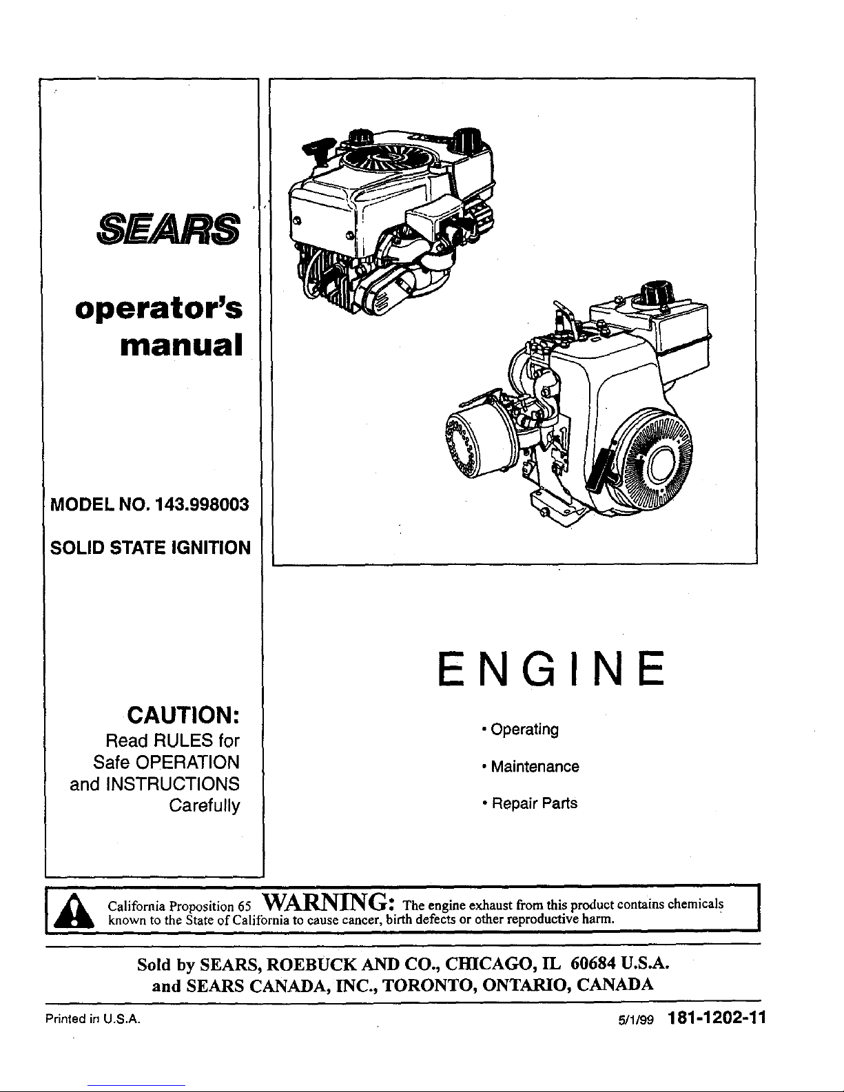
MODEL NO. 143.998003
SOLID STATE IGNITION
CAUTION:
Read RULES for
Safe OPERATION
and INSTRUCTIONS
Carefully
NGIN
• Operating
• Maintenance
• Repair Parts
d_lb California Proposition 65 WARNING: the engine exhaust from this product contains chemicals
known to the State of Caliibrnia to cause cancer, birth defects or other reproductive harm.
Sold by SEARS, ROEBUCK AND CO., CHICAGO, IT, 60684 U.S.A.
and SEARS CANADA, INC., TORONTO, ONTARIO, CANADA
Printedin U.S.A. 5/1199 181-1202-11
Page 2
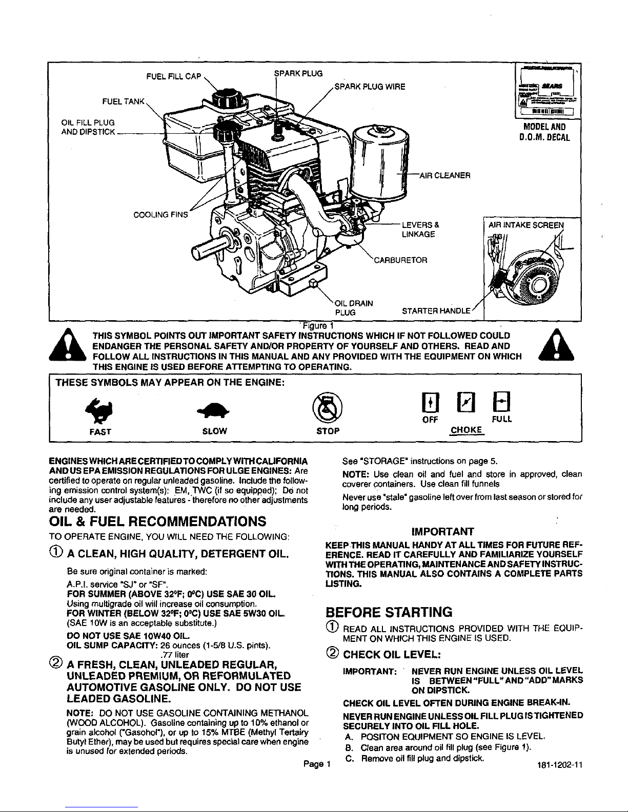
OIL FILL PLUG
AND DIPSTICK
SPARK PLUG
SPARK PLUG WIRE
MODELAND
D.O.M. DECAL
COOLING FINS
LINKAGE
OIL DRAIN
PLUG
'Figure t
THIS SYMBOL POINTS OUT IMPORTANT SAFETY INSTRUCTIONS WHICH IF NOT FOLLOWED COULD
ENDANGER THE PERSONAL SAFETY AND/OR PROPERTY OF YOURSELF AND OTHERS, READ AND
FOLLOW ALL INSTRUCTIONS IN THIS MANUAL AND ANY PROVIDED WITH THE EQUIPMENT ON WHICH
THIS ENGINE IS USED BEFORE ATTEMPTING TO OPERATING.
I THESE SYM4 BOLS MAY APPEAR ON THE ENGINE:
FAST SLOW
liBEl
OFF FULL
STOP CHOKE
AIR INTAKE SCREEN
ENGINES WHICH ARE CERTIFIEDTO COMPLYWITH CAUFORNIA
AND US EPA EMISSIONREGULATIONS FOR ULGE ENGINES: Are
certified to operate on regularunleadedgasoline. Includethe fo{Iow-
ing emission controlsystem(s): EM TWC {if so equipped); De not
{ncludeany user adjustablefeatures - thereforeno0theradjustments
are needed.
OIL & FUEL RECOMMENDATIONS
TO OPERATEENGINE.YOUWILL NEEDTHEFOLLOWING:
(_) A CLEAN, HIGH QUALITY, DETERGENT OIL.
Be sure original container is marked:
A.P.I. service "SJ"or "SF",
FOR SUMMER (ABOVE 32°F; 0°C) USE SAE 30 OIL.
Using multigrade oil wiUincrease oilconsumption.
FOR WINTER (BELOW 32°F; 0°C) USE SAE 5W30 OIL.
(SAE 10W is an acceptable substitute.)
DO NOT USE SAE 10W40 OIL.
OIL SUMP CAPACITY: 26 ounces (1-5/8 U.S. pints).
.77 liter
(_ A FRESH, CLEAN, UNLEADED REGULAR,
UNLEADED PREMIUM, OR REFORMULATED
AUTOMOTIVE GASOLINE ONLY. DO NOT USE
LEADED GASOLINE.
NOTE: DO NOT USE GASOLINE CONTAINING METHANOL
(WOOD ALCOHOL). Gasoline containing upto 10% ethanolor
grain alcohol ('Gasohol"), or up to 15% MTBE (Methyl Tertairy
ButylEther), may beused but requiresspecialcare when engine
is unused for extended periods.
Page 1
See "STORAGE" instructions on page 5.
NOTE: Use (::leanoil and fuel and store in approved, clean
coverer containers. Use clean fill funnels
Never use "stale" gasoline leftover from last season or stored for
long periods.
IMPORTANT
KEEPTHIS MANUAL HANDY AT ALL TIMES FOR FUTURE REF-
ERENCE. READ IT CAREFULLY AND FAMILIARIZE YOURSELF
WITH THE OPERATING, MAINTENANCE AND SAFETY INSTRUC-
TIONS. THIS MANUAL ALSO CONTAINS A COMPLETE PARTS
LISTING.
BEFORE STARTING
READ ALL INSTRUCTIONS PROVIDED WITH THE EQUIP-
MENT ON WHICH THIS ENGINE IS USED.
(_ CHECK OIL LEVEL:
IMPORTANT: NEVER RUN ENGINE UNLESS OIL LEVEL
IS BIETWEEN"FULL" AN D"ADD" MARKS
ON DIPSTICK.
CHECK OIL LEVEL OFTEN DURING ENGINE BREAK-IN.
NEVER RUN ENGINE UNLESS OIL FILL PLUG ISTIGHTENED
SECURELY INTO OIL FILL HOLE.
A, POSITON EQUIPMENT SO ENGINE IS LEVEL,
B. Clean area around oil fill plug (see Figure 1).
C. Remove oil fill plug and dipstick,
181-1202-11
Page 3

BEFORE STARTING (Continued)
D. Wipe dipstickclean, insert it into oil rill hole and tighten
securely.
E. Remove oil fill plug and check oil level. If level is notup to
"FULL" mark on dipstick,add recommended oil, until it is.
POUR SLOWLY.
Wipe dipstickclean each time oil level is checked.
DO NOT FILL ABOVE "FULL"MARK ON DIPSTICK.
F. Replace oil fill plugand tighten_je_urely.
See "MAINTENANCE" section for any future oil level and oil
change instructions(see Page 2).
(_ FILL FUEL TANK
with gasoline as specified in the preceding"OIL & FUEL
RECOMMENDATIONS" item 2.
NEVER MIX OIL WITH GASOLINE
Never use"stale" gasolineleftoverfrom last seasonorstoredfor
longperiods.
_IL EVER FILL FUEL TANK INDOORS. NEVER FILL FUELTAN K ]
WHEN ENGINE IS RUNNING OR HOT. DO NOT SMOKE
WHEN FILLILNG FUEL TANK.
_1 EVER FILL FUEL TANK COMPLETELY. FILL TANK TO 1/2" ]
BELOW BOTTOM OF FILLER NECK TO PROVIDE SPACE
FOR FUEL EXPANSION. WIPE ANY FUEL SPILLAGE FROM
ENGINE AND EQUIPMENT BEFORE STARTING ENGINE, /
ANY LIQUIFIED PETROLEUM (LPG)OR NATURAL GAS FUEL I
SYSTEM MUST BE LEAKPROOF AND MEET ALL APPLICA-
BLE CODES AND REGULATIONS.
(_ CHECK THE FOLLOWING:
STARTING (Continued)
_11=KEEP HANDS, FEET, HAIR AND LOOSE CLOTHING AWAY I
FROM ANY MOVING PARTS ON ENGINE AND EQUIPMENT.]
_1 WARNING: TEMPERATURE OF MUFFLER AND NEARBY
AREAS MAY EXCEED 150°F (65°C). AVO D THESE AREAS.
REWIND STARTER:
A.
Movechoke leverto FULL CHOKE POSITION.
NOTE: IF RESTARTING A WARM ENGINE AFTER A
SHORT SHUTDOWN, MOVE CHOKE LEVER TO "NO
CHOKE POSITION."
B. Moveequipmentcontrelto START (seaequipmentmanufac-
turer'sinstructions).
C. Gresp starter handle(see Figure2) and pullrepe out,slowly,
untilitpullsslightlyharder. Letrope rewindslowly.Then pull
ropewith a rapidfull arm stroke. Let rope rewindSLOWLY.
Do not let starterhandle snap back againststarter.
D. Repeat instructionC until enginefires. When enginestarts,
move choke lever to 1/2 CHOKE until engine runs smoothly
and then to NO CHOKE POSITION.
NOTE: If engine fires, but does not continueto run, move
choke leverto NO CHOKE POSITION and repeatinstruction
C untileng!nestarts.
Ifangine again fires, butdoes notcontinuetorun,movechoke
lever to FULL CHOKE POSITION and repeat instructionsC
and D untilengine starts.
(_ ELECTRIC STARTER (see Figures 2 and 3):
,_ A. BE SURE EQUIPMENT IS IN NEUTRAL GEAR WITH]
CLUTCHES, BELTS, CHAINS AND SAFETY SWITCHES
DISENGAGED. (FOLLOW EQUIPMENT MANUFACT- I
URER'S INSTRUCTIONS.) THIS SHOULD PLACE ANY
SAFETY SWITCHES IN SAFE STARTING POS TION.
B. Be surespark plugwire isattachedto sparkplug (see Figure
1).
C. Be sure anyignitionswitchon engine orequipment isin ON,
RUN or START position.
1- RECOIL 2 -ELECTRIC _
START IGNITIONSWITCHKEY
Figure2
CHOKE LEVER
NO CHOKE POSITION
_ITION
Figure 3
STARTING
A
NEVER RUN ENGINE INDOORS OR IN ENCLOSED, POORLY J
VENTILATED AREAS. ENGINE EXHAUST CONTAINS CAR- J
BON MONOXIDE, AN ODORLESS AND DEADLY GAS (CAR- I
BON MONOXIDE IS ALSO PRESENT IN ENGINE EXHAUST I
FROM LIQUID PETROLEUM (LPG) AND NATURAL GAS FUEL
SYSTEMS).
Page 2
A, Move choke lever to FULL CHOKE POSITION.
a.
C.
D,
NOTE: IF RESTARTING A WARM ENGINE AFTER A
SHORT SHUTDOWN, MOVE CHOKE LEVER TO
"NO CHOKE POSITION,"
MoveequipmentcontroltoSTART (see equipmentmanufac-
turer'sinstructions).
Pushstarterbuttonofturn ignitionswitchkey(see equipment
manufacturer'sinstructions)tocrank engine.
Crank engine until it fires. When it starts, release starter
button or ignitionswitch key and move choke lever to 1/2
CHOKE until engine runssmoothlyand thento NO CHOKE
POSITION.
Ifengine falters, move chokelever to1/2 CHOKE untilengine
runs smoothlyhand then to NO CHOKE POSITION.
NOTE: If engine fires, but does not continueto run, move
chokeleverto NO CHOKE POSITION and repeat instruction
C and D untilengine starts.
STOPPING
I_ Move equipmentcontrolor any ignitionstopswitchonengine
STOP or OFF (see equipment manufacturer's instructions).
(_ AFTER ENGINE IS STOPPED:
_,IA. DISCONNECT SPARK PLUG WIRE FROM SPARK PLUG I
AND KEEP IT AWAY FROM SPARK PLUG. I
_klB. TURN IGNmON SWITCH KEY (IF SO EQUIPPED) TO I
"OFF" POSITION AND REMOVE KEY FROM SWITCH. I
THIS WILL REDUCE THE POSSIBILITY OF UNAUTHO- I
RIZED STARTING OF ENGINE WHILE EQUIPMENT ISNOT
N USE. J
_IL NEVER STORE ENGINE WITH FUEL IN TANK INDOORS I
OR INENCLOSED, POORLY VENTILATED AREAS, WHERE I
FUEL FUMES MAY REACH AN OPEN FLAME, SPARK OR J
PILOT LIGHT AS ON A FURNACE, WATER HEATER,
CLOTHES DRYER OR OTHER GAS APPLIANCE.
181-1202-11
Page 4

MAINTENANCE
_ ARNING: TEMPERATUREOF MUFFLER AND NEARBYI
AREASMAY EXCEED150OF(65°C).AVOIDTHESEAREAS.
CHECK OIL LEVEL:
Check oillevel every five (5) operating hours or each time engine
is used. See "2CHECK OIL LEVEL" in "BEFORE STARTING" on
Page 1.
@ CHANGE OIL:
Change oil after first two (2) operating hours and every 25
operatinghours thereafter, more often if operated in extremely
dusty or dirty conditions.
Change oil while engine isstill warm from recentrunning.
_IA. DISCONNECT SPARK PLUG WIRE FROM SPARK PLUG 1
AND KEEP IT AWAY FROM SPARK PLUG, |
B. Clean area around drain plug (see Figure1).
C. Positionequipmentso engineoildrain plugislowestpointon
engine,
D. Remove oil drain plug and oil fill plug to drain oil
E. Replace oil drain plugand tighten securely,
F. Fill oil sump with recommended oil. See "OIL & FUEL REC-
OMMENDATIONS" and =CHECK OIL LEVEL" on Page 1.
G. Replace oil fill plug and tighten securely.
H. Wipe up any spilled oil.
(_AIR CLEANER
IMPORTANT: NEVER RUN ENGINE WITHOUT COMPLETE
AiR CLEANER INSTALLED ON ENGINE.
A. TO SERVICE FILTER(S) (see Figure 4):
1. FOAM FILTER:
Clean and re-oil every 3 months or every 25 operating
hours. Clean andre-oil daily if used in extremely dusty or
dirty conditions.
a, Wash in water and detergent solution and squeeze
(don't twist) until all dirt is removed.
b. Rinsethoroughly in clear water.
c. Wrap in a clean cloth and squeeze (don't twist) until
completely dry.
d. Saturate with engine oil and squeeze (don't twist) to
distributeoil and removeexcess oil.
2. PAPER FILTER:
DO NOT ATTEMPT TO CLEAN OR OIL FILTER.
Replace once a year or every t00 operatinghours,more
oftenif usedin extremely dusty conditions.
Replacement filters are available at any Sears Roebuch
and Co. (or Sears Canada, Inc.) Service Center.
B. TO REMOVE AND INSTALL RLTER:
1. Remove wing nut and cover.
2. Slidefoam filteroffpaper filter..
3. Inspectfilters for discolorationor dirtaccumulation. If
eitherispresent,serviceperpreceding"TO SERVICE
FILTER(S)" instructions.
4. Remove nut and paperfilter (if service is necessary).
5. Clean topside of base and inside ofcover thoroughly.
6. Installpaper filter and nut. Tightennut fingertightand
then turn it one (1) more completeturn.
7. Slidefoam filter over paper filter,
8. Installcover and wing nut. Tighten wing nut.
Page 3
MAINTENANCE (Continued)
_WING NUT
NUT
BASE--
Figure4
(_ SPARK PLUG (seeFigure5)=
This spark ignitionsystem meets al[ requirementsofthe Cana-
dianInterference-CausingEquipment Regulations. This engine
complieswithall currentAustralianand New Zealand limitatiOns
regardingelectromagneticinterference. Check spark plugyeady
or every 100 operatinghours.
A. Clean area around spark plug.
B. Remove and inspect spark plug.
C. Replace spark plugif electrodes are pitted,burnedor por-
celain is cracked. For replacementuse ChampionRJ17LM
or equivalent.
NOTE: A resistorspark plug mustbe usedfor replacement.
D. Check electrode gap with wire feeler gauge and setgap at
.030 if necessary.
E. Install spark plug,tightensecurely.
ELECTRODES
.030 GAP
Figure5
(_ COOLING SYSTEM (seeFigure1):
IMPORTANT: Frequentlyremovegrassclippings,dirtand debris
fromcooling fins, air intake screen and levers and linkage. This
willhelp ensure adequate cooling and correctenginespeed.
(_)'CHECK ENGINE AND EQUIPMENT OFTEN FOR LOOSE]
_1= NUTS, BOLTS AND AI"FACHMENTS, AND KEEP THESE_
I ITEMS TIGHTENED.
ADJUSTMENTS
DO NOT MAKE UNNECESSARY ADJUSTMENTS. FACTORY SET
TINGS ARE SATISFACTORY FOR MOST APPLICATIONS AND
CONDITIONS. IF ADJUSTMENTS ARE NEEDED, PROCEED AS
FOLLOWS:
(_ CARBURETOR (see Figure6):
If you think your carburetor needs adjusting, see your nearest
SEARS, ROEBUCK AND CO. (OR SEARS CANADA, INC.)
SERVICE CENTER. Engine performanceshouldnotbe affected
at altitudesup to7,000 feet. For operation at higher elevation,
contactyour nearest SEARS, ROEBUCK AND CO. (OR SEARS
CANADA, INC.) SERVICE CENTER.
18t-1202-11
Page 5

ADJUSTMENTS (Continued)
(_ REMOTE CONTROL (seeFigure7):
Forsatisfactoryengine performance,engine and remote equip
ment controlsmustbeadjusted properly.Tocheckenginecontrol
adjustments,proceed as follows:
A. Set remoteequipmentcontrolat FAST or HIGH SPEED and
keep inthis position.
In this position,engine CONTROL LEVER should touch
HIGH SPEED STOP. If itdoes, the controlsare adjustedcor
rectly and no further adjustmentshouldbe necessary.
NOTE: Ifengine CONTROL LEVER does nottouch HIGH
SPEED STOP, proceed toinstructionB.
B. Loosen CLAMP SCREW so REMOTE CONTROL CABLE
can be moved in CABLE CLAMP (do not remove CABLE
CLAMPfrom CONTROL BRACKET ordisconnectREMOTE
CONTROL CABLE from CONTROL LEVER.)
C. Move engine CONTROL LEVER so _t is touching HIGH
SPEED STOP and hold it inthis position.
D. Tighten CLAMP SCREW securely so CABLE CLAMP will
holdREMOTE CONTROL CABLE inplace when equipment
controlisused.
The engine controlsshould now be adjusted correctly.
If additional control adjustments are necessary, contact your
nearby Sears Roebuck and Co. (Sears Canada, Inc.) Service
Center.
(_) ENGINE SPEED:
_1 NEVER TAMPER WITH ENGINE GOVERNOR WHICH IS FAC- I
TORY SET FOR PROPER ENGINE SPEED. OVERSPEEDING I
ENGINE ABOVE FACTORY HIGH SPEED SETTING CAN BEI
DANGEROUS. I
CHANGING OF ENGINE-GOVERNED SPEED WILL VOID
ENG NE WARRANTY.
FOR ANY MAJOR ADJUSTMENTS OR REPAIRS, CONTACT
YOUR NEARBY SEARS ROEBUCK AND CO. (OR SEARS
CANADA, INC.) SERVICE CENTER.
CARBURETOR
BOWL DRAIN_
Figure 6
CONTROL CONTROL
BRACKET _ SCREW
STORAGE
A
NEVER STORE ENGINE WITH FUEL IN TANK INDOORS OR1
INENCLOSED, POORLY VENTILATED AREAS, WHERE FUEL|
FUMES MAY REACH AN OPEN FLAME, SPARK OR PILOT/
UGHT AS ON A FURNACE, WATER HEATER, CLOTHES/
DRYER OR OTHER GAS APPLIANCE. |
IF ENGINE IS TO BE UNUSED FOR 30 DAYS OR MORE,
PREPARE AS FOLLOWS:
(!) DRAIN FUEL SYSTEM:
A. Remove all gasoline from carburetorand fuel tank to prevent
gum deposits from forming on these parts and causing possi-
ble malfunction of engine.
_L DRAIN FUEL INTO APPROVED CONTAINER OUTDOORS,1
WAN ?O"oO; NFLAMESESUREE"G'"E'SCOOL/
B. Run engine until fuel tank is empty and engine stops due to
lack of fuel.
NOTE: Fuel stabilizer (such as STA-BIL) is an acceptable
a_ternative in minimizing the formation of fuel gum deposits
dudngstorage. Addstabilizertogasoline in fueltank or storage
container.Always follow mix ratio found on stabilizercontain-
er, Run engine at least 10 minutes after adding stabilizerto
allow it toreach carburetor.
(_) CHANGE OIL:
Changeoilifithasnotbeenchangedinthelastthree(3)months.
See"CHANGEOIL"instructionsin "MAINTENANCE"sectionon
Page3.
(_) OIL CYLINDER BORE:
A. Remove spark plug. Squirfone (1) oz. (30 ml)of clean engine
oil into spark plug hole.
B. Crank engine over, slowly, several times.
_ AVOID SPRAY FROM SPARK PLUG HOLE WHEN CRAN K-
ING ENGINE OVER SLOWLY.
C. Replace spark plug.
(_ CLEAN ENGINE:
Removeanyclippings,dirt,orchafffromexteriorofengine.
GENERAL
Justas yourautomobile needsprofessionalmechanicalmaintenance
fromtimetotime, sodoes yourCraftsmanengine. Replacementofthe
spark plug and air cleaner is made necessary by NORMAL use.
ProfessionalAir-Ceeled Engine Service isas close as your nearest
Sears Roebuckand Co. (orSears Canada, Inc.) Service Center.
A yearly check-up or tune-up by Sears is a good idea to avoid
breakdownsor delay.., do it at the end of the season, then you're
ready for the next. We even prepare it forstoragefor you.
Figure 7
Page 4 181-1202-11
Page 6

TROUBLESHOOTING
THE FOLLOWING MAY HELP AVOID A DELAY IN YOUR WORK OR
SAVE THE EXPENSE OF A SERVICE CALL,
ENGINE FALLSTO START OR STARTS WITH DIFFICULTY
CAUSE
Controlsnot in start position.
Spark plug wire disconnected from spark plug.
Spark plug fouled.
Spark plug porcelaincracked,
Insufficientfuel.
Water ordirt in fuel.
Improper carburetoradjustment
ENGINE LACKS POWER
CAUSE
Dirtyair cleaner.
Impropercarburetoradjustment.
Lack of lubricaiton.
ENGINE MISSES UNDER LOAD
CAUSE
Spark plug fouled,
Spark plug porcelain cracked.
Improperspark pluggap,
Impropercarburetoradjustment
REMEDY
Move ENGINE CONTROL or equipment controlto "HI"or
START postien. See "STARTING" instructionsinthis
manual.
Connect SPARK PLUGWIRE toSPARK PLUG,
Remove SPARK PLUG and clean it. See "SPARK PLUG"
instructionsin "MAINTENANCE" section in this manual.
Installnew spark plug.
FillFUEL TANK per "BEFORE STARTING" instructions,
Drain FUEL TANK andre-fill withclean, freshgasoline. See
"BEFORE STARTING" instructionsinthis manual.
Adjust carburetor(if applicable). See "ADJUSTMENTS"
section in thismanual.
REMEDY
Replace or clean air cleaner per "AIR CLEANER"
instructionsin "MAINTENANCE" section inthis marluaL
Adjust carburetor(if applicable). See "ADJUSTMENTS"
sectionin this manual.
'Filloil sump to proper level. See "BEFORE STARTING"
instructions section in this manual.
REMEDY
Remove SPARK PLUG and clean it, See "SPARKPLUG"
instructionsin "MAINTENANCE" section in this manual,
Installnew SPARK PLUG,
!Regap SPARK PLUG electrodes, See "SPARK PLUG"
instructions in "MAINTENANCE" section inthis manual.
Adjustcarburetor (if applicable). See "ADJUSTMENTS"
section nth s manua.
181-1202-11
Page 5
Page 7

SEARS, ROEBUCK AND CO.
Federal and California Emission Control Systems Limited Warranty
Utility and Lawn and Garden Engines
CALIFORNIA & US EPA EMISSION CONTROL
WARRANTY STATEMENT
The U S Environmental Protection Agency (*EPA'), the California Air Resources
Board ('CARB') and Sears, Roebuck andCo, are pleased to explain the Federal
and California Emission Controt Systems Warranty on yournew utility or lawn and
garden equipment engine. In California, new 1995 and later utiEtyand lawn and
arden equipment engines must be designedt bailsand equipped to meet the
_fata's stringent anti-smog standards. In other states, new 1997 and later model
year engines must be designed, built and equipped, at the time of sale. to meet
the U.E. EPA regulabons for small non-road engines Sears Roebuck and Co
will warrant the emission control system on your utility or lawn and garden
equipment engine for the periods of time listod below, provided there has been no
abuse, neglect, unapproved modification, orimproper maintenance of your utility
or lawn and garden equipment engine
Your emission control system may include parts such as the carburetor, ignition
system and exhaust system, Also inoluded may be the compression release
system and other emission-related assemblies¸
Where a warrantable condition exists, Seats. Roebuck and Oo. will repair your
utility ot lawn and garden equipment engine 8t no cost to you for diagnosis, parts
and labor
MANUFACTURER'S EMISSION CONTROL SYSTEM
WARRANTY COVERAGE
Emission control systems on 1995 and later model year California ubliltyand fawn
and garden equipment engines are warranted for two years as hereinafter noted
In other states, 1997 and later model year engines are also warranted for two
years. If, during such warranty period, any emission-related part on your engine
=sdefective in materials or workmanship, the part witl be repaired or replaced by
Sears, Roebuck and Co.
OWNER'S WARRANTY RESPONSIBILITIES
As the utilityor lawn and garden equipment engine owner, you are responsible for
the performance of the required maintenance listed in your Owner's Manual. but
Sears Roebuck and Co will not deny warranty solely due to the lack of receipts
or for your failure to provide wr tten evidence of the pedormance of all scheduled
maintenance.
As the utilityot lawn and garden equipment engine owner, you should, however,
be aware that Sears, Roebuck and Co may deny you warranty coverage if your
utilityor lawn and garden equipment or a part thereof has failed due to abuse.
neglect, improper maintenance or unapproved modifications
You are responsible for presenting your utilityor lawn and garden equipment
engine to a Sears. Roebuck and Do. Authorized Service Outlet as soon as a
problem exists. The warranty repairs soduld be completed Jna reasonable
amount oftime, not to exceed 30 days
Warranty service can be arranged by contacting either a Seat=, Roebuck and Co.
Authorized Service Outlet, or bycontacting Sears, Roebuck and Co at 1-800*
473-7247¸
IMPORTANT NOTE
This warranty statement explains your rights and obligations under the Emission
Contrbl System Warranty ('ECS Warranty') which is provided to you by Sears.
Roebuck and Co, pursuant to Oatifornia law. See also the Sears, Roebuck and
CO. Limited Warranties for Sears. Roebuck and Co, which is enclosed therewith
on a separate sheet and also is provided to you by Sears, Roebuck and Co, The
ECS Warranty applies only to the emission control system of your new engine,
TO the extent that there is any conflict in terms between the ECS Warranty and
the Sears. Roebuck and Co. Warranty, the ECS Warranty shaft apply except in
any circumstances in which the Sears, ROebuck and Co Warranty may provide a
longer warranty period. Both the ECS Warranty and the Sears, Roebuck and Co,
Wa_anty describe important rights and obligations with respect to your new
engine.
Warranty service can only be performed by a Sears, Roebuck and Co. Authorized
Service Outlet, At the time of requesting warranty service, evidence must be
presented ofthe date of sale to the original purchaser. The purchaser shall pay
any charges for makin_ servJcecallsandlorfortransporfingthe pfroducts to a_ld
from the place where the inspection and/or warranty work is performed. The
purchaser shall be responsible for any damage or loss incurred in connection with
the transportation of any engine or any pert(s) thereof submitted for inspection
and/or warranty work,
If you have any questions regarding your warranty rights and responsibilities, you
should contact Sears, Roebuck and CO. at 1-500-473-7247
EMISSION CONTROL SYSTEM WARRANTY
Emission Control System Warranty "ECS Warranty" for 1995 and later model
year California utilityand lawn and garden equipment engines for other states.
1997 and later model year engines):
A. APPLICABILITY: This warranty shall apply to 1995 and later model year
California utilityand lawn and garden equipment engines for other states. 1997
and later model year engines). The ECS Warranty Pedod shaft begin on the date
the new engine or equipment is defivered to its original, end-use purchaser and
shall continue for 24 consecutive months thereafter.
R. GENERAL EMISSIONS WARRANTY COVERAGE: Sears, Roebuck and CO.
warrants to the original, end-use purchaser of the new engine or equipment and
to each subsequent purchaser that each of its utifityand lawn and garden
equipment engines is:
1 Designed. built and eduipped so as to conform with all applicable
regulations adopted by the Air Resources Eoard pursuant to its authority in
Chapters 1 and 2, Part 5. Division 26 of the Health and Safety Code, and
2 Free from defects in materials and workmanship which, at any time duhng
the ECS Warranty Period, will cause a warranted emissions*related part to
fair to be identicat in all material respects to the part as described in the
engine manufacturer's application rbr certification
C. The ECS Warranty only pertains to emissions-relatad parts on your engine, as
follows:
1. Any warranted, emissions-related partswhich are not scheduled for
replacement as required thblntena nce in the Owner's Manual shall be
warranted for the ECS Warranty Period If any such part fails during the
ECS Warranty Period, itshall be repaired or replaced by Sears, Roebuck
and Co according to Subsection 4 below Any such part repaired or
replaced under the ECS Warranty shall be warranted for any remainder of
the ECS Warranty Period,
2,
Any warranted, emissions-refatad part which is scheduled only for regular
inspection as specified in the Owner's Manual shall be warranted for the
ECS Warranty Period A statement in such written instructions to the
effect of "repair or replace as necessary', shall not reduce the ECS
Warranty Period Any such part repaired or replaced under the ECS
Warranty shall be warranted for the remainder of the ECS Warranty
Period.
Any warranted, emissions-related part which is scheduled for replacement
as required maintenance inthe Owner's Manual. shall be warranted for the
period of time prior to the first scheduled replacement point for that part. If
the part fails pdor to the first scheduled replacement, the part shallbe
repaired or replaced bySears, Roebuck and Co according to Subsection
4 below Any such emissions-related part repaired or replaced under the
ECS Warranty, shall be warranted for the remainder of the ECS Warranty
Period prior to the first scheduled replacement point for suchemissions-
related part.
4 Repair or replacement of any warranted, emissions-related part under this
ECS Warranty shall be performed at no charge to the owner at a Sears,
Roebuck and Co. Authorized Service Outlet
fi The owner shall not be charged for diagnostic fabor which leads to the
determination thata part covered by the ECS Warranty is in fact defective,
provided that such diagnostic work is performed at a Sears, Roebuck and
CO. Authorized Service Outlet
5 Sears, Roebuck and Co. shall be fiable for damages to otheroriginbl
engine components or alp|provedmodifications proximately caused bya
failure under warranty of an emission-related part covered by the ECS
Warranty,
7. Thro_Jghoutthe ECS Warranty Period. Sears. Roebuck and Co shall
maintain a sgppty of warranted emission-related parts sufficient to meet
the expected demand for such emission-related parts,
8 Any Sears, Roebuck and Co. authorized and approved emission*refated
replacement part may be used in the performance of any ECE Warranty
maintenance or repaJr and will be provided without chaa_a to the owner¸
Such use shall not reduce Sears, Roebuck and Co ECS Warranty
obligations.
9,
Unapproved edd-on or modified parts may not be used to modify or repair
a Sears. Roebuck and Co. engine. Such use voidsthis ECS Warranty and
shall be sufficient grounds for disallowing an ECS Warranty claim. Seats,
Roebuck and Oo. shall not be Jiable hereunder for failures of any
warranted pads of a Sears. Roebuck and CO. engine caused by the use of
such an unapproved add-on or modified part.
EMISSION-RELATED PARTS INCLUDE THE FOLLOWING:
1. Carburetor Assembly and its Internal Components
a) Fuel filter
b) Carburetor gaskets
c) Intake pipe
2, Air Cleaner Assembly
a) Air filter e_ement
3. Ignition System. including:
a) Spark plug
b) Ignition module
C) Flywheel assembly
4 Catalytic Muffler (if so equipped)
a) Muffler gasket (if so equipped)
b) Exhaust manifold (if SOequipped)
5 Crankcase Breather Assembly and its Components
_,) _.reather co_nectk_n t_be
12297 Ep,VCAR]_
Sears, Roebuck and Co., Hoffman Estates, IL 60179 U.S.A.
Page 6 181o1202-11
Page 8

CRAFTSMAN 4-CYCLE ENGINE MODEL:143.998003
/.
Jr/
lOl
182
245A
Page 7 181-1202-11
Page 9

CRAFTSMAN 4-CYCLE ENGINE MODEL:143.998003
Ref. Part
No. No.
1
2
15
15A
15B
16
17
18
19
2O
25
26
28
30
35
36
37
38
40
40
41
41
42
42
43
45
47
48
49
5O
6O
65
69
70
71
72
75
8O
81
82
83
84
86
87
89
90
92
93
100
101
102
103
110
119
120
125
125
126
126
127
128
130
130A
130B
35385
27652
30599C
30700
650494
33454
29916
651028
34663
35319
36460
650561
30322
35372A
29826
29918
29216
29642
40011
40012
40009
40010
40013
40014
27888
36897
651033
34034
36896
35375
33273A
650128
"35262A
35376
35377
27642
35319
31845
30590A
35378
30588A
29193
650833
650832
32589
611091
650880
650881
35135
610118
651024
651007
35187
*36448
36449
27878A
27880A
34035
34036
650691
650690
650694A
650727
651055
Ref. Part
Part Name No. No.
Cylinder (Incl. 2, 20 & 72) 135
Dowel Pin 139
Governor Rod (,Incl. 15A & 15B) 140
Governor Y5ke 149
Screw, 6-40 x 5/16" 149A
Governor Lever 150
Governor Lever Clamp 151
Screw, Tom "1"-15,8-32 x 3/8" 169
Speed Control Spring 170
Oil Seal 171
Blower Housing Baffle 172
Screw, 1/4-20 x 5/8" 173
Lock Nut, 8-32 173A
Crankshaft 174
Screw, 10-32 x 3/4" 178
Lock Washer 182
Lock Nut, 10-32 184
Retaining Ring 185
Piston, Pin & Ring Set (Std.) 186
Piston, Pin & Ring Set (.010" OS) 200
Piston & Pin Ass'y. (Std.) (Incl. 43)
Piston & Pin Ass'y. (.010" OS) (Incl. 203
43) 204
RingSet (Std.) 206
RingSet (.010" OSi 207
Piston Pin Retaining Ring 209
Connecting Rod Aas'y. (Incl. 47 & 49) 210
Connecting Rod Bolt 211
Valve Lifter 223
Oil Dipper 224
Camshaft (MCR) 227
Blower Housing Extension
Screw, 10-24 x 1/2" 228
Cylinder Cover Gasket 229
CylinderCover (Incr.71, 75 & 80) 232
Crankshaft Bushing
Oil Drain Plug 235
Oil Seal 238
Governor Shaft 239
Washer 239A
GovernorGear Ass'y. (Incl. 81) 241A
Governor Spool 242
Retaining Ring 245
Screw, 1/4-20 x 1-3/16" 245A
Screw, 1/4-20 x 1-11/16" 250
Flywheel Key 251
Flywheel 260
Lock Washer 261
Flywheel Nut 262
Solid State Ignition 264A
Spark Plug Cover 265
Solid State MountingStud 281
Screw, Tcrx To15, 10-24 x 15/16" 282
Ground Wire 285
Cylinder Head Gasket 287
Cylinder Head 290
ExhaustValve (Std.) (Incl. 151) 291
ExhaustValve (1/32" OS) (IncL 151) 292
IntakeValve (Std.) (Incl. 151)
Intake Valve (1/82" OS) (Incr. 151)
Washer
Belleville Washer
Screw, 5/16-18 x 2"
Screw,5/16-18 x 1-3/4"
Screw, 5/16-18 x 5/8"
Page 8
33636
33369
650836
27882
35862
27881
32581
"27896A
28423
28424
28425
34696
32446
650128
2975_
30088A
*33263
34707
34667
34664
31342
651029
610973
33878
650821
27793
28942
650378
"27915A
35044
650851
650852
30675
650163
"27272A
"34698A
37279
34699
34700A
34703
34702
659886
34833S
650788
29747B
650802
33272S
33013
650760
359858
29752
29774
30962
26450
Part Name
Resistor Spark Plug (RJ17LM)
Govemcr Gear Bracket
Screw, 10-24 x 1/2"
Valve Spring Cap
Valve Spring Cap
Valve Spdng
IValve Spring Keeper
Breather Gasket
Breather Body
Breather Element
Valve Cover
Breather Tube
Breather Tube Grommet
Screw, 10-24 x t/2"
Nut & Lock Washer, 1/4-28
Screw, 1/4-28 x 1"
Carburetor To Intake Pipe Gasket
In_ke Pipe
Governor Link
Control Bracket (Incl. 19, 203, 204 &
209)
Compression Spring
Screw, Torx "1"-10,5-40 x 7/16"
Terminal
Throttle Link
Screw, 10-32 x 1/2"
Conduit Clip
Screw, 10-32 x 3/8"
Screw, Torx T-30, 5/16-18 x 1-1/8"
Intake Pipe Gasket
Air Cleaner Elbow (Incl. 228, 229,
234, 239 & 242)
Stud, 1/4-20 x 8.1
Nut, 1/4-20
Pop Rivet (1/8=Dia.)(Purehase
Locally)
Air Cleaner Elbow Fitting
Screw, 10-32 x_7/8"
Air Cleaner Gasket
Air Cleaner Gasket
Air Cleaner Collar
Air Cleaner Bracket
Air Cleaner Filter
Air Cleaner Filter
Air Cleaner Cover
Wing Nut, 1/4-20
Blower Housing
Screw, 5/16-18 x 3/4"
Screw, Torx T-40, 5/16-24 x 21/32"
Screw, 1/4-20 x 5/8"
Cylinder Head Cover
Starter Bubble Cover
Screw, 8-32 x 3/8"
Starter Cup
Nut & Loc;kWasher, 1/4-28
Fuel Line
Fuel Line
Fuel Line Clamp
*Indicates Parts Included in
Gasket Set, Ref. No. 400.
181-1202-11
Page 10

CRAFTSMAN 4-CYCLE ENGINE MODEL:143.998003
Re[ Part
No. No.
293 35807
294 35791
298 650665
300 34156A
301 36246
303 32958
305 35554
307 35499
308 35540
310 36205
325 29443
327 35392
340 34154
341 34155
342 650561
370E 37O89
370G 35274
Pad Name
Pulse Pump
Pulse Pump Repair Kit
Screw, 1/4-15 x3/4"
Fuel Tank (IncL 292 & 301)
Fuel Cap
FuelFitting
Oil Fill Tube
"O" Ring
Fill Tube Clip
Dipstick
Wire Clip
Starter Plug
Fuel TankBracket
Fuel TankBracket
Screw, 1/4-20 x 5/8"
Air Cleaner Decal
Oil InstructionDecal
Ref.
No.
380
390
400
90O
900
Part
No.
640153
590746
36450B
181-1202-11
Part Name
Carburetor (Incl. 184)
Rewind Starter
(NOTE: This engine could have
been built with 590704 starter.)
Gasket Set (Incl. Items Marked *)
Replacement Engine 756335, Order
From 71-999
Replacement Short Block, 756316A
Order From 71-999
Operator's Manual
*Indicates Parts Included in
Gasket Set, Ref. No. 400.
RPM High 3450 to 3750
RRM Low 1700
CARBURETOR NO. 640153
, 1o
I 30
,_27 //
/
/I
/ 86
Ref. Part
No. No. Pert Name
640153 Carburetor (incl. 184 of Engine Parts List
1 631776,_ Throttle Shaft & Lever Assembly
2 631970 Throttle Return Spring
4 631184 Dust Seal Washer
5 631183 Dust Seal (Throttle)
6 640109 Throttle Shutter
7 650506 Shutter Screw
10 632177 Choke Shalt& Lever Assembly
11 632043 Choke Return Spring
• 12 631184 Dust Seal Washer
13 631183 Dust Seal (Choke)
14 631753 Choke Shutter
15 630735 Choke Positioning Spring
16 631807 Fuel Fitting
17 651026 Throttle Crack Screw/idle Speed Screw
18 630766 Tension Spring
20 640027 Idle Restdctor Screw
20A 640053 Idle Restdctor Screw Cap
25 631867 Float Bowl
27 631024 FLoatShaft
28 632019 Float
29 631028 Float Bow1"O" Ring
30 631021 inlet Needle, Seat & Clip (incl. 31)
31 631022 Spring Clip
36 640113 Main Nozzle Tube
37 632547 Main Nozzzle Tube "O" Ring
40 640114 High Speed Bowl Nut
44 27110 Bowl Nut Washer
47 630748 Welch Plug. Idle MixtureWell
48 631027 Welch Plug. AtmosphericVent
Page 9 181-1202-11
Page 11

REWIND STARTER NO. 590746
12
"8
¢p-.4
1
Rof. Part
No. NO, Part Name
590746
1 590599A
2 590600
3 590679
4 590601
5 590678
6 590680
7 590412
8 590661
11 590747
12 590535
13 590701
Recoil Starter
Spring Pin(Incl. 4)
Washer
Retainer
Washer
Brake Spring
Starter Dog
Dog Spring
Pulley & Rewind SpringAss'y.
Starter HousingAss'y.
Starter Rope ( 98"X 9/64" dia.)
Starter Handle
STARTER NO, 590704
/
13
12
8
_--5
O--2
Ref, Part
No. No. Part Name
590704 Recoil Starter
1 590599A Spring Pin (Ind+ 4)
2 590600 Washer
3 590696 Retainer
4 590601 Washer
5 590697 Brake Spdng
6 590698 Starter Dog
7 590699 Dog Spring
8 590700 Pulley & Rewind Spring Ass'y,
t 1 590705 Starter Housing Ass'y.
12 590535 Starter Rope ( 98' x 9/64" dia.)
13 590701 Starter Handle
Page 10 181-1202-!1
Page 12

operator's
manual
MODEL NO. 143.998003
SOLID STATE IGNITION
CAUTION:
Read RULES for
Safe OPERATION
and INSTRUCTIONS
Carefully
How to ORDER Repair Parts
The Model Numbercan be found on a decal on the blower
housing (See Figure 1). Always mention the Model Number
when requesting service or repair parts for your Craftsman
Engine.
All parts listed herein may be ordered from any SEARS, ROE-
BUCK AND GO. or SEARS CANADA, INC. retailor catalog store.
Ifthe partsyou need are not stocked locally,yourorder willbe
electronicallytransmittedtoa Sears Repair Parts Distribution
Centerfor expedited handling.
WHEN ORDERING REPAIR PARTS, ALWAYS GIVE THE
FOLLOWING INFORMATION AS SHOWN IN THIS LIST.
1. The PART NUMBER
2. The PART DESCRIPTION
3. The MODEL NUMBER
4. The NAME OF ITEM - ENGINE
"Your Sears merchandise has addedvalue when you considerthat Sears has
service units nationwide staffed with Sears trained technicians.., professional
technicians specifically trained on Sears products, having the parts, tools and
equipmentto insure thatwe meet our pledge to you ... we service what we sell."
Sold by SEARS, ROEBUCK AND CO., CHICAGO, IL 60684 U.S.A.
and SEARS CANADA, INC., TORONTO, ONTARIO, CANADA
t81-1202-11
 Loading...