

Page 1
SEARS
operator's
manual
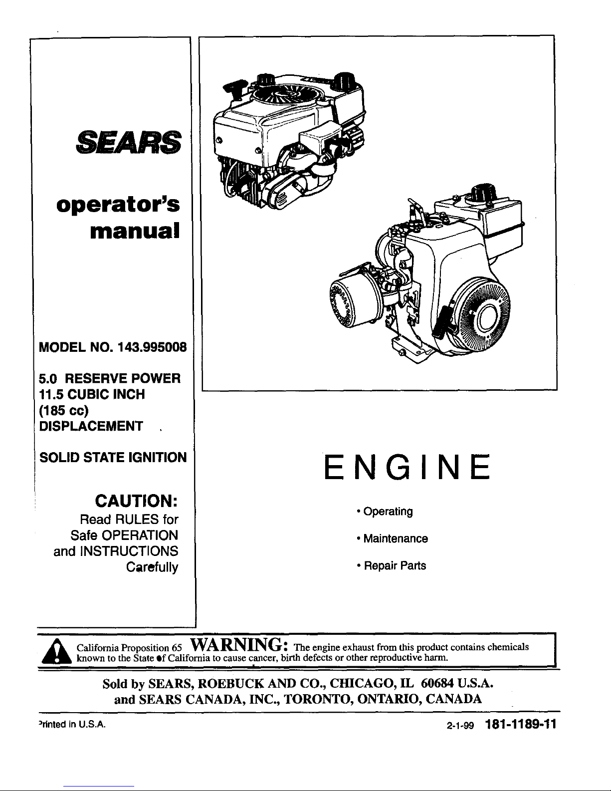
MODEL NO. 143.995008
5.0 RESERVE POWER
11.5 CUBIC INCH
(185cc)
DISPLACEMENT
SOLID STATE IGNITION
CAUTION:
Read RULES for
Safe OPERATION
and INSTRUCTIONS
Carefully
ENGIN
• Operating
• Maintenance
• Repair Parts
i
Cali_omi a P_'op°sition 65 WA_TG_ Tt_e e_'_gine exhaust _*'om th_s D['oduct co_t_taln_, chemlc_S I
known to the State Qf California to cause cancer, birth defects or other reproductive harm.
|
Sold by SEARS, ROEBUCK AND CO., CHICAGO, IL 60684 U.S.A.
and SEARS CANADA, INC., TORONTO, ONTARIO, CANADA
"rinted in U.S.A. 2-1-99 181-1189-11
Page 2
MIIIIIII#|MII
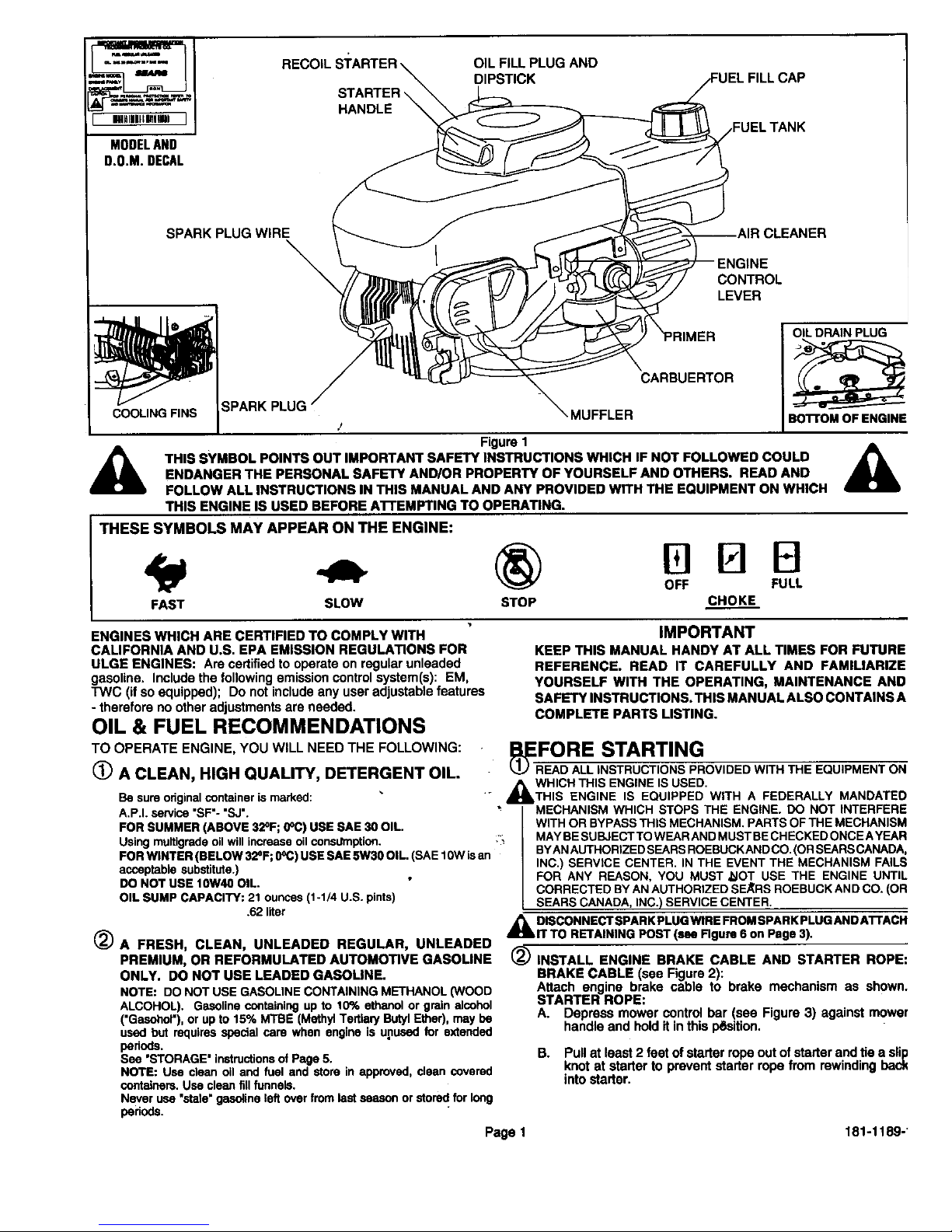
MODELAND
D.O.M.DECAL
RECOIL OIL FILL PLUG AND
DIPSTICK IEL FILL CAP
STARTER_
HANDLE
SPARK PLUG WIRE CLEANER
CONTROL
LEVER
COOLING FINS
OIL DRAIN PLUG
CARBUERTOR
_MUFFLER
/
Figure 1
THIS SYMBOL POINTS OUT IMPORTANT SAFETY INSTRUCTIONS WHICH IF NOT FOLLOWED COULD
ENDANGER THE PERSONAL SAFETY AND/OR PROPERTY OF YOURSELF AND OTHERS. READ AND
FOLLOW ALL INSTRUCTIONS IN THIS MANUAL AND ANY PROVIDED WITH THE EQUIPMENT ON WHICH
THIS ENGINE IS USED BEFORE AI"rEMPTING TO OPERATING.
THESE SYMBOLS MAY APPEAR ON THE ENGINE:
MBB
OFF FULL
FAST SLOW STOP CHOKE
Bo'n'OM OF ENGINE
ENGINES WHICH ARE CERTIFIED TO COMPLY WITH
CALIFORNIA AND U.S. EPA EMISSION REGULATIONS FOR
ULGE ENGINES: Are cedified to operate on regular unleaded
gasoline. Include the following emission control system(s): EM,
TWC (if so equipped); Do not include any user adjustable features
- therefore no other adjustments are needed.
OIL & FUEL RECOMMENDATIONS
TO OPERATE ENGINE, YOU WILL NEED THE FOLLOWING:
(_ A CLEAN, HIGH QUALITY, DETERGENT OIL.
Be sure original container is marked:
A.P.I. service "SF'- "SJ',
FOR SUMMER (ABOVE 32°F; 0°C) USE SAE 30 OIL.
Using muitigrede oil will increase oil consdmption.
FOR WINTER (BELOW 32°F; (PC) USE SAE 5W30 OIL. (SAE 10W is an
acceptable substitute.)
DO NOT USE 10W40 OIL.
OIL SUMP CAPACITY: 21 ounces (1-1/4 U.S. pints)
,62 liter
_J A FRESH, CLEAN, UNLEADED REGULAR, UNLEADED
PREMIUM, OR REFORMULATED AUTOMOTIVE GASOLINE
ONLY. DO NOT USE LEADED GASOLINE.
NOTE: DO NOT USE GASOLINECONTAINING METHANOL(WOOD
ALCOHOL). Gasoline containingup to 10% ethanol or grain alcohol
('Gasohol'), or up to 15% MTBE (MethylTertisP/Butyl Ether),may be
used but requires specialcare when engineis unused for exlended
periods.
See 'STORAGE" instructionsof Page 5.
NOTE: Use clean oil and fuel and store in approved, clean covered
containers.Use cleanfillfunnels.
Never use"stele"gasolineleft overfrom lastseason or stored for long
periods.
IMPORTANT
KEEP THIS MANUAL HANDY AT ALL TIMES FOR FUTURE
REFERENCE. READ IT CAREFULLY AND FAMILIARIZE
YOURSELF WITH THE OPERATING, MAINTENANCE AND
SAFETY INSTRUCTIONS. THIS MANUAL ALSO CONTAINS A
COMPLETE PARTS LISTING.
JI EFORE STARTING
_ I_OVIDED WITHTHE EQUIPMENT ON
,_kWHICH THIS ENGINE IS USED.
THIS ENGINE IS EQUIPPED WiTH A FEDERALLY MANDATED
MECHANISM WHICH STOPS THE ENGINE. DO NOT INTERFERE
WITH OR BYPASS THIS MECHANISM. PARTS OFTHE MECHANISM
:_ MAYBESUBJECTTO WEARANDMUSTBECHECKEDONCEAYEAR
BYANAUTHORIZEDSEARSROEBUCKANDCO.(ORSEARSCANADA,
INC.) SERVICE CENTER. IN THE EVENT THE MECHANISM FALLS
FOR ANY REASON, YOU MUST ,_IOT USE THE ENGINE UNTIL
CORRECTED BYANAUTHORIZEDSE_RS ROEBUCKAND CO. (OR
SEARSCANADA, INC.) SERVICE CENTER.
,_ DISCONNECTSPARKPLUGWIREFROMSPARKPLUGANDATTACH
IT TO RETAINING POST (see Figure 6 on Page 3).
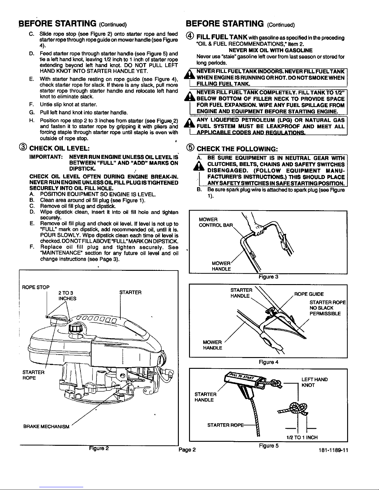
2_ INSTALL ENGINE BRAKE CABLE AND STARTER ROPE:
BRAKE CABLE (see Figure 2):
Attach engine brake cable to brake mechanism as shown.
STARTER ROPE:
A. Depress mower control bar (see Figure 3) against mower
handle and hold it in this p_sition.
B. Pull at least 2 feet of starter rope out of starter and tie a slip
knot at starter to prevent starter rope from rewinding back
into starter.
Page 1 181-1189-1
Page 3
BEFORE STARTING (Continued)
C. Slide rope stop (see Figure2) onto starter ropeand feed
starterropethroughropeguideonmowerhandle(seeFigure
4).
D. Feedstarterropethroughstarter handle(see Figure5) and
tiea lefthandknot,leaving112inchto I inchof starterrope
extendingbeyond left hand knot. DO NOT PULL LEFT
E,
F.
G.
H.
BEFORE STARTING (Continued)
(_ FILL FUEL TAN Kwith gasoline as specified inthe preceding
"OIL & FUEL RECOMMENDATIONS," item 2.
NEVER MIX OIL WITH GASOLINE
Never use =stale"gasoline left over from last season or stored for
long pedods.
HAND KNOT INTO STARTER HANDLE YET. _IL NEVER FILL FUELTANK INDOORS. NEVER FILL FUELTANK
With starter handle resting on rope guide (see Figure 4), _ WHENENGINEISRUNNINGORHOT.DONOTSMOKEWHEN
check starter rope for slack. If there is any slack, pull more L FILLING FUEL TANK.
starter rope through starter handle and relocate left hand A NEVER RLL FUEL TANK COMPLETELY. FILL TANK TO 1/2"
knot to eliminate slack. _ BELOW BOTTOM OF FILLER NECK TO PROVIDE SPACE
Untie slip knot at starter. / FOR FUEL EXPANSION. WIPE ANY FUEL SPILLAGE FROM
Pull left hand knot into starter handle. L ENGINE AND EQUIPMENT BEFORE STARTING ENGINE.
Position rope stop 2 to 3 inches from starter (see Figure 2) ,_ ANY LIQUEFIED PETROLEUM (LPG) OR NATURAL GAS
and fasten it to starter rope by gdpping it with pliers and _ FUEL SYSTEM MUST BE LEAKPROOF AND MEET ALL
forcing staple through starter rope until staple is even with I APPLICABLE CODES AND REGULATIONS.
outside of rope stop.
(_) CHECK OIL LEVEL:
IMPORTANT: NEVER RUN ENGINE UNLESS OIL LEVEL IS"
BETWEEN "FULL" AND "ADD" MARKS ON
DIPSTICK. .,
CHECK OIL LEVEL OFTEN DURING ENGINE BREAK-IN.
NEVER RUN ENGINE UNLESS OIL FILL PLUG IS TIGHTENED
SECURELY INTO OIL FILL HOLE.
A. POSITION EQUIPMENT SO ENGINE IS LEVEL.
B. Clean area around oil fill plug (see Figure 1).
C. Remove oil fill plug and dipstick.
D. Wipe dipstick clean, insert it into oil fill hole and tighten
securely.
E. Remove oil fill plug and check oil level. If level is not up to
=FULL" mark on dipstick, add recommended oil, until it is.
POUR SLOWLY, Wipe dipstick clean each time oil level is
checked. DO NOT FILLABOVE "FULL"MARK ON DIPSTICK.
F. Replace oil fill plug and tighten securely. See
=MAINTENANCE" section for any future oil level and oil
change instructions (see Page 3).
ROPE STOP
2TO3
INCHES
STARTER
STARTER
ROPE
f
BRAKEMECHANISM •
(_) CHECK THE FOLLOWING:
A. BE SURE EQUIPMENT IS IN NEUTRAL GEAR WITH
,_ CLUTCHES, BELTS, CHAINS AND SAFETY SWITCHES
DISENGAGED. (FOLLOW EQUIPMENT MANU-
• FACTURER'S INSTRUCTIONS.) THIS SHOULD PLACE
ANY SAFETY SWITCHES IN SAFE STARTING POSITION.
B. Besure spark plug wire isattached to spark plug(see Figure
1).
MOWER
CONTROLBAR
HANDLE
Figure 3
STARTER _
HANDLE \\ ROPEGUIDE
\\\ / STARTERROPE
"_=fJk'_Z NO SLACK
_ PERMISSIBLE
MOWER " '_ _.
HANDLE
Figure 4
STARTER
HANDLE
LEFT HAND
KNOT
1/2TO 1INCH
Figure 2 Page 2 Figure 5 181-1189-11
Page 4
STARTING
_ NEVER RUN ENGINE INDOORS ORIN ENCLOSED, POORLY
VENTILATED AREAS. ENGINE EXHAUST CONTAINS
CARBON MONOXIDE, AN ODORLESS AND DEADLY GAS
(CARBON MONOXIDE IS ALSO PRESENT IN ENGINE
EXHAUST FROM LIQUID PETROLEUM (LPG) AND NATURAL
GAS FUEL SYSTEMS),
KEEP HANDS, FEET, HAIR AND LOOSE CLOTHING AWAY
,_ FROM ANY MOVING PARTS ON ENGINE AND EQUIPMENT.
_k WARNING TEMPERATURE OF MUFFLER AND NEARBY
AREAS MAY EXCEED 150°F (65=C). AVOID THESE AREAS.
I_ Move engine control (see Figure 1) to HI Position.
b
(_) START ENGINE:
A. The carburetor on your engine has been completely _ldjusted
at the factory. When starting a cold engine, push red pdmer
bulb firmly with your thumb 5 times, allowing pdm_r bulb
to return completely to odginal position between pushes.
Repeat the above for each starter operation as necessary.
NOTE: DO NOT USE PRIMER'TO RESTART A WARM
ENGINE AFTER A SHORT SHUTDOWN.
B. Operate mowercontroltoreleaseengine brake.
C. Graspstarterhandle(seeFigure4) andpullropeout,slowly,
untilit pullsslightlyharder.Letroperewindslowly.Thenpull
ropewitha rapidfull arm stroke.LetroperewindSLOWLY.
Do notlet starter handlesnapbackagainstropeguide(see
Figure4).
D. RepeatinstructionsBandC ifnecessary,untilenginestarts.
NOTE: If enginedoesnotstart,repeatinstructionsA, B,C
and D untilitstarts.
ENGINE SPEED: Enginespeed is controlledbythe enginecoqtrol
(see Figure1). EnginecontrolshouldbeinHI positionforhighgrass
conditionsand for mostefficientbagginginheavygrassconditions,
and in LOW positionfor lightgrass,trimmingandfor fuel economy.
STOPPING
(_) Sea mower manufacturer's instructions.
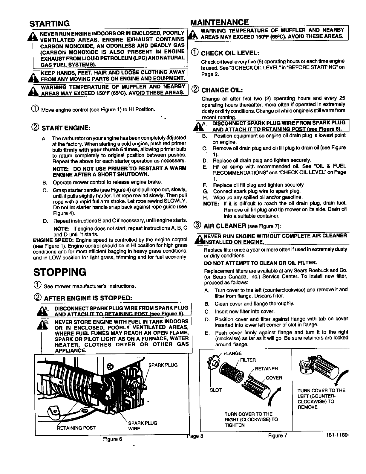
(_ AFTER ENGINE IS STOPPED:
MAINTENANCE
_1 WARNING TEMPERATURE OF MUFFLER AND NEARBY i
AREAS MAY EXCEED 150°F (6b'aC). AVOID THESE AREAS.
CHECK OIL LEVEL:
Checkoilleveleveryfive(5)operatinghoursoreachtimeengine
isused.See"3 CHECKOILLEVEL"in"BEFORESTARTING"on
Page2.
_) CHANGE OIL:
Change oil after first two (2) operating hours and every 25
operating hours thereafter, more often if operated in extremely
dustyor dirtyconditions.Change oil while engine isstillwarm from
recent running.
_. DISCONNECT SPARK PLUG WIRE FROM SPARK PLUG
I
AND A'I-FACH IT TO RETAINING POST (see Flqum 6). j
B. Positionequipmentsoengineoildrainplugislowestpoint
on engine.
C. Removeoildrainplugandoilfillplugto drainoil (seaFigure
1).
D. Replaceoildrainplugand tightensecurely.
E. Fill oil sump with recommended oil. See "OIL & FUEL
RECOMMENDATIONS"and=CHECKOIL LEVEL"onPage
1.
F. Replaceoilfill plugandtightensecurely.
G. Connectsparkplugwireto sparkplug.
H. Wipe upany spilledoiland/orgasoline.
NOTE: If it is diff'multto reach the oil drain plug, drain fuel.
Removeoilfill plugandtip moweron itsside.Drainoil
intoa suitablecontainer.
AIR CLEANER (see Figure7):
_IINNEVER RUN ENGINE WITHOUT COMPLETE AIR CLEANER
STALLED ON ENGINE.
Replacefilteronceayearormoreoftenifusedinextremelydusty
or dirtyconditions.
DONOT ATTEMPT TO CLEAN OR OIL FILTER.
Replacementfiltersareavailableatany Sears RoebuckandCo.
(or Sears Canada, Inc.) Service Center. To installnew tilter,
proceedas follows:
A. Turncoverto the left(counterclockwise)andremoveitand
filter from flange. Discardfilter.
B. Clean coverandflangethoroughly.
_" C.
HEATER, CLOTHES DRYER OR OTHER
/
DISCONNECT SPARK PLUG WIRE FROM SPARK PLUG |
ANn ATTAP.I.I IT T_ R_"rAIMINP. PNRT (.._t_ I:ln.rp R) Insert new filter into cover.
NEVER STORE ENGINE WITH FUEL IN TANK INDOORS,, i D. Position cover and filter against flange with tab on cover
OR IN ENCLOSED, POORLY" VENTILATED AREAS inserted into lower left comer of slot in flange.
WHERE FUEL FUMES MAY REACH AN OPEN FLAME E. Push cover firmly against flange and turn it to the right
SPARK OR PILOT LIGHT AS ON A FURNACE, WAGTER/ around(Cl°Ckwise)flange.aSfar as it will go. Be sure retainers are locked
/
FLANGE
_,_.,_ / F,LTER
" (IRP /R ,,NER
T
TURN CO'
RIGHT (CI
TIGHTEN
a_
APPLIANCE.
RETAINING POST
Figure 6
SPARKPLUG
,PARK PLUG
WIRE
TURN COVER TO THE
LEFT (COUNTER°
CLOCKWISE)TO
TURN COVER TO THE
RIGHT (CLOCKWISE)TO
ge 3 Figure 7 181-1189-1
Page 5

•MAINTENANCE (Continued)
(_ SPARK PLUG (see Figure8):
This spark ignitionsystem meets allrequirements ofthe Canadian
Interferenca-Causing Equipment Regulations. This engine
complies with all current Australian and New Zealand limitations
regarding slectromagnstic interference. Check spark plug yeady
or every 100 operating hours.
A.
B.
C.
O.
E.
Cleanarea aroundsparkplug.
Remove and inspect spark plug•
Replace spark plugifelectrodes are pitted, burned orporcelain
is cracked. For replacement use Champion RJ19LM.
NOTE: A resistorsparkplugmustbe usedfor replacement.
Checkelectrodesgapwithwirefeelergaugeand setgal_at
,030 if necessary.
Install spark plug, tighten securely.
ELECTRODES
.030 GAP
Figure8
PORCELAIN
_) COOLING SYSTEM:
IMPORTANT: Frequently remove any grass clippings, dirt and
debris from cooling fins, air intake screen and levers and linkage
(see Figure 1). This will help ensure adequate cooling and correct
engine speed.
CHECKENGINEANDEQUIPMENTOFTENFORLOOSENUTS,]
BOLTS AND A'I-rACHMENTS, AND KEEP THESE ITEMS /
TIGHTENED.
ADJUSTMENTS
DO NOT MAKE UNNECESSARY ADJUSTMENTS. FACTORY
SETTINGS ARE SATISFACTORY FOR MOST APPLICATIONS AND
CONDITIONS• IF ADJUSTMENTS ARE NEEDED, PROCEED AS
FOLLOWS:
(_ CARBURETOR
If you think your carburetor needs adjusting, see your nearest
SEARS, ROEBUCK AND CO. (OR SEARS CANAD,_, INC.)
SERVICE CENTER. Engine performance should not be affected
at altitudes up to 7,000 feet. For operation at higher elevations,
contact your nearest SEARS, ROEBUCK AND CO. (OR SEARS
CANADA, INC.) SERVICE CENTER.
(_ ENGINE SPEED
NEVER TAMPER WITH ENGINE GOVERNOR WHICH IS
FACTORY SET FOR PROPER ENGINE SPEED.
OVERSPEEDING ENGINE ABOVE FACTORY HIGH SPEED
SETnNG CAN BE DANGEROUS.
CHANGING OF ENGINE_OVERNED SPEED WILL VOIO
ENGINE WARRANTY.
STORAGE
1
NEVER STORE ENGINE WITH FUEL IN TANK INDOORS OR /
_lb IN ENCLOSED, POORLYVENTILATED AREAS,WHERE FUEL {
FUMES MAY REACH AN OPEN FLAME, SPARK OR PILOT_
LIGHT AS ON A FURNACE, WATER HEATER, CLOTHES|
DRYER OR OTHER GAS APPLIANCE.
J
IF ENGINE IS TO BE UNUSED FOR 30 DAYS OR MORE,
PREPARE AS FOLLOWS:
(_ DRAIN FUEL SYSTEM:
A. Removeallgasolinefromcerburator andfueltanktoprevent
gum deposits from forming on these parts and causing
possible malfunctionofengine.
,_ DRAIN FUEL INTO APPROVED CONTAINER OUTDOORS,
AWAY FROM OPEN FLAME. BE SURE ENGINE IS COOL
[ DO NOT SMOKE.
B,
Runengineuntilfueltank is emptyandenginestops dueto
lackoffuel.
NOTE: Fuelstabilizer(suchasSTA-BIL)isan acceptable
alternativeinminimizingthe formation offuel gumdeposits
dudng storage. Add stabilizerto gasolinein fuel tank or
storagecontainer.Alwaysfollowmixratiofoundonstabilizer
container. Run engine at least 10 minutes after adding
stabilizertoallowit to reachcarburetor.
(_ CHANGE OIL:
Changeoilif ithasnotbeenchangedinthelastthree(3)months.
See "CHANGE OIL"instructionsin=MAINTENANCE"sectionon
Page 3,
(_) OIL CYLINDER BORE:
A. Removesparkplugandpourone(1) ounce(30ml) ofengine
• oilintosparkplughole.
B. Cover sparkplughole witha rag.
C. Crank enoineover.slowlv,severaltimes.
_IL AVOID SPRAY FROM SPARK PLUG HOLE WHEN
CRANKING ENGINE OVER SLOWLY.
I
D. Replacesparkplug.
J
CLEAN ENGINE:
Removeanyclippings,dirt,or chafffromexteriorof engine.
GENERAL
Justas your automobile needs professional mechanical maintenance
fromtime to time, so does your Craftsman engine. Replacement of the
spark plug and air cleaner is made necessary by NORMAL use.
Professional Air-Cooled Engine Service is as close as your nearest
Sears Roebuck and Co. (or Sears Canada, Inc.) Service Center.
A yearly check-up or tune-up by Sears is a good idea to avoid
breakdowns or delay.., do it at the end of the season, then you're
ready for the next. We even prepare it for storage for you.
Page 4 181-1189-11
Page 6

TROUBLESHOOTING
THE FOLLOWING MAY HELP AVOID A DELAY IN YOUR WORK OR
SAVE THE EXPENSE OF A SERVICE CALL.
ENGINE FAILS TO START OR STARTS WITH DIFFICULTY
CAUSE REMEDY
Controlsnotinstart position. Move ENGINE CONTROL or equipmentcontrolto "HI"or
Sparkplugwiredisconnectedfromsparkplug.
Spark plugfouled.
Sparkplugporcelaincracked.
Insufficientfuel.
Water or dirtinfuel.
Impropercarburetoradjustment
START postion. See "STARTING"instructionsinthis
manual.
ConnectSPARK PLUGWIRE to SPARK PLUG.
RemoveSPARK PLUG andcleanit. See "SPARK
PLUG"instructionsin "MAINTENANCE"sectioninthis
manual.
Installnewsparkplug.
FillFUELTANK per "BEFORESTARTING"instructions.
DrainFUELTANKand re-fillwithclean,fresh gasoline.
See 'BEFORE STARTING"instructionsinthismanual.
Adjustcarburetor(ifapplicable).See "ADJUSTMENTS"
sectioninthismanual.
ENGINE LACKS POWER
CAUSE
Dirty air cleaner.
Impropercarburetoradjustment.
Lackof lubricaiton.
REMEDY
Replace or clean air cleaner per "AIR CLEANER"
instructions in "MAINTENANCE" section in this manual.
Adjustcarburetor (if applicable).See "ADJUSTMENTS"
sectioninthismanual.
Filloilsumptoproperlevel. See "BEFORESTARTING"
instructionssectioninthismanual.
ENGINE MISSES UNDER LOAD
CAUSE
Sparkplugfouled.
Spark plugporcelaincracked.
Impropersparkpluggap.
Impropercarburetoradjustment
REMEDY
Remove SPARK PLUG and clean it. See "SPARK
PLUG" instructions in "MAINTENANCE" section in this
manual.
Install new SPARK PLUG.
RsgapSPARKPLUG electrodes.See "SPARKPLUG"
instructionsin "MAINTENANCE"sectioninthismanual.
Adjustcarburetor(ifapplicable). See "ADJUSTMENTS"
sectioninthismanual.
Page 5 181-1189-11
Page 7

SEARS, ROEBUCK AND CO.
Federal and California Emission Control Systems Limited Warranty
Utility and Lawn and Garden Engines
CALIFORNIA & US EPA EMISSION CONTROL
WARRANTY STATEMENT
The U. S. Environmental Protection Agency ('EPA'), the California Air Resources
Board ('CARB') and Sears, Roebuck andCo, are pleased to explain the Federal
and Cstifomia Emission Control Systems Warranty onyour new utility or lawn and
garden equipment engine. In California, new 1995 andlater utility and lawn and
_arden equipment engines must be designed, built and equipped to meet the
fate's stringent anti-smog standards. In other states, new 1997 and later model
year engines must be designed, built and equipped at the time of sale to meet
the U.S. EPA regulations for small non-road engines. Sears Roebuck and Co.
will warrant the emission control system on your utility or lawn and garden
equipment engine for the periods of time listed below, provided there has been no
abuse, neglect, unapproved modification or improper maintenance of your utility
or lawn and garden equipment engine.
Your emission control system may include_epartssuch as the carburetor ignition
system and exhaust system. Also included may be the compression release
system and other emission-rstated assemblies.
Where a warrantable condition exists, Sears Roebuck and Co. will repair your
an_aber.Utilior lawn and garden equipment engine at no cost to you for diagnosis, parts
MANUFACTURER'S EMISSION CONTROL SYSTEM
WARRANTY COVERAGE
Emission control systems on 1995 and later model year California utiliityand lawn
and garden equipment engines are warranted for two years as hereina{ter no eq
in other states, 1997 and later model year engines are also warranted for two
years. If, during such warranty pedod, any emission-rstal_eq part on your engine
is defective in materials or workmanship, the pert will be lepeireq or replaces by
Sears, Roebuck and Co.
OWNER'S WARRANTY RESPONSIBILITIES
As the utility or lawn and garden equipment engine owner you are responsible for
the performance of the required maintenance listed in your Owner's Manual but
Sears, Roebuck and Co. will not deny warranty solely due o the ack of receipts
or for your failure to provide written evidence of the performance of a I schequ ed
maintenance,
As the utility or lawn and garden equipment engine owner you should, however.
be aware that Sears, Roebuck and Co. may deny you warranty coverage you
utility or lawn and garden equipment or a part thereof has failed due o abuse
neglect, improper maintenance or unapproved rood cat ons.
YOU are responsible for presenting your utility or lawn and garden equ pment
engine to a Sears, Roebuck and Co. Authorized Service Outlet as soon as a
problem exists. The warranty repairs should be completed in a reasonable
amount of time, not to exceed 30 days.
Warranty service can be arranged by contacting either a Sears Roebuck and Co.
Authorized Service Outlet, or by contacting Sears, Roebuck and Co. at 1-800-
473-7247.
IMPORTANT NOTE
This warranty statement explains your rights and obligations under the Emission
Control System Warranty {=ECS Warranty') which is provided to you by Sears
Roebuck and Co. pursuant to California law. See also the Sears, Roebuck and
Co. Limited Warranties for Sears, Roebuck and Co. which is enclosed therewith
on a separate sheet and also is provided to you by Sears, Roebuck and Co. The
ECS Warranty applies only to the emission control system of your new engine.
TO the extent that there is any conflict in terms between the ECS Warranty and
the Sears, Roebuck and Co. Warranty the ECS warranty shall apply exoep n
any circumstances in which the Sears, Roebuck and CO Warranty may provide a
longer warranty period. Bo h he ECS Warranty and the Sears. Roebuck and Co.
Warranty describe important rights and obligations with respect o your new
engine.
Warranty service can only be performed by a Sears Roe_)uck and Co Au hor zed
Service Outlet. At the time of requesting warranty service, evidence must be
presented of the date of sale to the original purchaser. The purchaser shall pay
any charges for making service calls and/or for transporbn_;i theproduc § to and
from the place where the inspection and/or warranty work _sperformed. The
purchaser shall be responsible for any dams e or loss incurred in connection with
the transportation of any engine or any pert(_ thereof submitted for inspection
and/or warranty work.
If you have any questions regarding your warranty rights and respons b as, you
should contact Sears, Roebuck and Co. at %800-473-7247.
EMISSION CONTROL SYSTEM WARRANTY
Emission Control System Warranty (=ECS Warranty') for 1995 and later model
year California utility and lawn and garden equipment engines (for other states,
1997 and later model year engines):
A. APPLICABILITY: This warranlty shall apply to 1995 and later mode year
California utility and lawn and garden equipment engines (for other states, 1997
and later model year engines. The ECS Warranty Period shall begin on he date
the new engine or equipment is delivered to its original end-use purcbeser, and
shall continue for 24 consecut ve months iltereafter.
B. GENERAL EMISSIONS WARRANTY COVERAGE: Sears, Roebuck and Co.
warrants to the odginst, eed-use purchaser of the new engine or equipment and
to each subsequent purchaser that each of its utility and lawn and garden
equipment engtnes is:
t. Designed, built and equi ped so as to conform with all applicable
regulations adopted by t_e Air Resources Board pursuant to its authority in
Chapters 1 and 2, Part 5, Division 25 of the Health and Safety Code, and
2. Free from defects in materials and workmanship which, at any time during
the ECS Warranty Period, will cause a warranted emissions-related part to
fail to be identical in all matedal respects to the part as described in the
engine manufacturer's application for certification.
C. The ECS Warranty only pertains to emissions-related parts on your engine, as
follows:
1. Any warranted, emissions-relateq parts which are not scheduled for
replacement as required maintenance in the Owner's Manual shall be
warranted for the ECS Warranty Period. If any such part fails dedng the
ECS Warranty Period, it shall be repaired or replaced by Sears Roebuck
and Co. according to Subsection 4 below. Any such part repaired or
replaced under the ECS Warranty shall be warranted for any remainder of
the ECS Warranty Period.
2. Any warranted, emissicns-re]ated part which is scheduled only for regular
inspection as specified in the Owner's Manual shall be warranted for the
ECS Warranty Pedod. A statement in such written instructions to the
effect of "repair or replace as necessary', shall not reduce the ECS
Warranty Period. Any such pert repaired or replaced under the ECS
Warranty shall be warranted for the remainder of the ECS Warranty
Pedod.
3. Any warranted, emissicns*related part which is scheduled for replacement
as reequiredmaintenance in the Owner's Manual sheJI be warranted for the
period of time phor to the first scheduled replacement point for that part. If
the part fails phor to the first scheduled replacement the part shall be
repaired or replaced by Seam, Roebuck and Co. according to Subsection
4 below. Any such emissions-reJated part repaired or re laced under the
ECS Warranty, shall be warranted for the remainder of t_e ECS Warranty
Period prior to the first scheduled replacement point for such emissions-
related part.
4. Repair or replacement of any warranted, emissions-relateq part under this
ECS Warranty shall be performed at no charge to the owner at a Sears
Roebuck and Co. Authorized Service Outlet.
5. The owner shall not be charged for diagnostic labor which leads to the
determination that a part covered by the ECS Warranty is in fact defective
provided that such diagnostic work is performed at a Sears Roebuck and
Co. Authorized Service Outlet.
6. Sears, Roebuck and Co. shall be liable for damages to other original
engine components or a proved modifications proximately caused by a
failure under warranty o_°a_nemission-related part covered by the ECS
Warranty,
7. Throughout the ECS Warranty Period Sears Roebuck and Co sha
maintain a supply of warranted emission-relatad parts sufficient to meet
the expected demand for such emission-relatad parts.
8. Any Sears, Roebuck and Co. authorized and approved emission-related
replacement part may be used in the performance of any ECS Wa ranty
maintenance or repair and will be provided without cha e to the owner.
Such use shall not reduce Sears, Roebuck and Co. E_ Warranty
obligations.
9. Unapproved add-on or modified parts may not be used to modify or repair
a Sears, Roebuck and Co. engine. Such use voids this ECS Warranty and
shall be sufficient grounds for disallowing an ECS Warranty claim. Sears,
Roebuck and Co. shaft not be liable hereunder for failures of any
warranted parts of a Sears, Roebuck and Co. engine caused by the use of
such an unapproved add-on or modified part.
EMISSION-RELATED PARTS INCLUDE THE FOLLOWING:
t. Carburetor Assembly and its Interest Components
a) Fuel filter
b) Carburetor gaskets
c) tntake pipe
2. Air Cleaner Assembly
a) Air filter element
3. Ignition System, including:
a) Spark plug
b) Ignition module
c) Flywhest assembly
4. Catalytic Muffler (if so equipped)
a) Muffler gasket (if so equipped)
b) Exhaust manifold (if so equipped)
5. Crankcase Breather Assembly and its Components
a) Breather connection tube
.Sears, Roebuck and Co., Hoffman Estates, IL 60179 U.S.A.
Page 6 181-1189-11
Page 8

CRAFTSMAN 4-CYCLE ENGINE MODEL:143.995008
_-- 370K
_'3gO
400
135
130
275A 120
416 119
,284
284A
125
101
126
,lO0
215_
2O4
182
185
178
3O
207
52
7
2g(?
_310
Page 7 181-1189-11
Page 9

CRAFTSMAN 4-CYCLE ENGINE MODEL:143.995008
Ref. Pan
No. No.
1 37266
2 26727
6 33734
7 36557
12 36775
12A 36558
12B 36694
14 28277
15 30589
16 34839A
17 31335
18 651018
19 36281
20 32600
30 36776
40 40004
40 40005
41 36070
41 36071
42 40006
42 40007
43 20381
45 36777
46 32610A
48 27241
50 36778
52 29914
69 *35261
70 34311E
72 36083
75 27897
80 30574A
81 30590A
82 30591
83 30588A
86 650488
89 611004
90 611112
92 650815
93 650816
100 34443S
101 610118
103 651007
110 37047
119 *36787
120 36825
125 37288
126 37289
130 6021A
135 35395
150 31672
151 31673
151A 40017
169 *36783
172 36784
174 30200
178 29752
Part Name
Ref.
No.
Part
No.
Cylinder (Incl. 2, 20 & 150)
Dowel Pin
Breather Element
Breather Ass'y. (Incl. 6 & 12A)
Breather Tube
Breather Cover & Tube (Incl. 12B)
Breather Tube Elbow
Washer
Governor Rod (Incl. 14)
Govemor Lever
P
Governor Lever Clamp
Screw, Torx T-15, 8-32 x 19/64"
Extension Spring
Oil Seal
Crankshaft
Piston, Pin & Ring Set (Std.)
Piston, Pin & Ring Set (.010" OS)
Piston & Pin Ass'y,_(Std.) (Incl. 43)
Piston & Pin Ass'y. (.010" OS) (Incl.
43)
Ring Set (Std.)
Ring Set (.010" OS)
Piston Pin Retaining Ring
Connecting Rod Ass'y. (Incl. 46)
Connecting Rod Bolt
Valve Uffer
Camshaft (MCR)
Oil Pump Ass'y.
Mounting Flange Gasket
Mounting Flange (Incl. 72 thru 83,
306)
Oil Drain Plug
Oil,Seal
Governor Shaft
Washer
Governor Gear Ass'y. (Incl. 81)
Governor Spool
Screw, 1/4-20 x 1-1/4"
Flywheel Key
Flywheel
Belleville Washer
Flywheel Nut
Solid State Ignition
Spark Plug Cover.
Screw, Torx T-15, 10-24 x 15/16"
Ground Wire
Cylinder Head Gasket
Cylinder Head
Exhaust Valve (Std.) (Incl. 151)
Intake Valve (Std.) (Incl. 151)
Screw, 5/16-18 x 1-1/2"
Resistor Spark Plug (RJ19LM)
Valve Spring
Valve Spdng Cap
Intake Valve Seal
Valve Cover Gasket
Valve Cover
Screw, 10-24 x 9_'16"
Nut & Lock Washer, 1/4-28
182
184
185
186
189
191
195
200
202
203
204
205
207
209
215
223
224
238
239
241
i 245
i 250
260
261
262
275
275A
277
284
284A
285
287
290
292
298
300
301
305
306
307
309
310
313
325
370A
370B
370C
370K
6201
*26756
36785
34337
650839
36568
610973
35727
36482
31342
651029
651030
34336
30200
32410
650451
*36786
650932
*34338
35797
35066
35065
36980
30200
650831
36837A
36838A
650988
36663
650821
35000A
650926
29774
26460
28763
36916
36246
35647
*36996
35499
650562
35648
34080
37152
36261
35167
37199
36695
Part Name
Screw, 1/4-28 x 7/8"
Carburetor To Intake Pipe Gasket
Intake Pipe
Governor Link
Screw, 1/4-20 x 3/8"
S.E. Brake Bracket (Incl. 195)
Terminal
Control Bracket (Incl. 202 thru 205)
Compression Spring
Compression Spdng
Screw, Torx T-10, 5-40 x 7/16"
Screw, Torx T-10, 6-32 x 17/32"
Throttle Link
Screw, 10-24 x 9/16"
Control Knob
Screw, 1/4-20 x 1"
Intake Pipe Gasket
Screw, 10-32 x 49164"
Air Cleaner Gasket
Air Cleaner Collar
Air Cleaner Filter
Air Cleaner Cover
Blower Housing
Screw, 10-24 x 9/16"
Screw, 1/4-20 x 1/2"
Muffler
Spark Arrestor Kit (Optional) (IncL
284, 284A, 416, 417)
Screw, 1/4-20 x 2-5/16"
Muffler Deflector (Incl. 284A)
(Optional)
Screw, 10-32 x 1/2" (Optional)
Starter Cup
Screw, 8-32 x 21/64"
Fuel Line
Fuel Line Clamp
Screw, 10-32 x 35/64"
Fuel Tank (Incl. 292 & 301)
Fuel Cap
Oil Fill Tube
"O"-Ring
"O"-Ring
Screw, 19-32 x 1/2"
Dipstick
Spacer
Spdng Clip
Lubdcation Decal
Control Decal
Pdmer Decal
Starter Decal
*IndicatesParts Includedin
GasketSet, Ref. No.400.
Page8 181-1189-11
Page 10

CRAFTSMAN 4-CYCLE ENGINE
Ref. Pad
No. No.
380 640174
390 590737
400 36792B
416 36085
417 650821
R_. Pad
Pad Name No. No.
Carburetor (Incl. 184)
Rewind Starter
(NOTE: This engine could have
been built with 590694 starter).
Gasket Set (Incl. Items Marked *)
Spark Arrestor Kit (Incl. 417)
(Optional)
Screw, 10-32 x 1/2" (Optional)
900
900
181-1189-11
MODEL: 143.995008
Part Name
Replacement Engine 750818A,
order from 71-999
Replacement Short Block 750796B,
order from 71-999
Operator's Manual
*IndicatesParts Includedin
GasketSet, Ref. No. 400.
RPM High2900 to 3200
RPM Low2450 to 2750
:ARBURETOR NO. 640174
Ref. I Part
No. No. Part Name
640174
1 631615
2 631767
4 *631184
5 "631183
6 640070
7 "650506
16 631807
17 651025
18 630766
20 640018
20A 640053
26 631867
27 *631024
28 632019
29 *631028
30 *631021
31 631022
35 36045A
36 640080
36A 632766
37 "632547
,_ 640175
2711OA
*631027
632760
Carburetor (Incl. 184 of Engine Parts Lisq
Throttle Shaft & Laver Assembly
Throttle Return Spdng
Dust Seal Washer
Dust Seal (Throttle)
Throttle Shutter
Shutter Screw
Fuel Fitting
Throttle Crack Screw/Idle Speed Screw
Tension Spring
Idle Restrictor Screw
Idle Restdctor Screw Cap
Float Bowl
Float Shaft
Float
Float Bowl "O" Ring
Inlet Needle, Seat, & Clip (Incl, 31)
Spdng Clip
Pdmer Bulb/Retainer Ring
Main Nozzle Tube
Carburetor Tube
_O" Ring, Main Nozzle Tube
High Speed Bowl Nut
Bowl Nut Washer
Welch Plug, Idle Mixture Well
Welch Plug, Atmospheric Vent
Welch Plug
Repair kit (incl. Items Marked *)
Page 9 181-1189-11
Page 11

REWIND STARTER NO. 590737
_14
13
R_'. Part
No. No. Part Name
3
6
7
8
11
12
13
14
590737
590740
590616
590617
590618A
590687A
590535
590701
590760
Rewind Starter
Retainer
Starter Dog
Dog Spring
Pulley & Rewind Spring Ass'y
Starter Housing Ass'y (40 degree
grommet)
Starter Rope (Length 98" x 9/64"
dia.)
Starter Handle
Spring Clip
STARTER NO. 590694
/
13
12
m8
7
s--_O w 6
- 4
B_ 5
Q m 2
R_. Part
No. No. Pad Name
1
2
3
4
5
6
7
8
11
12
13
590694
590599A
590600
590696
590601
590697
590698
590699
590700
590695
590535
590701
RecoilStarter
SpringPin (Incl. 4)
Washer
Retainer
Washer
Brake Spring
StarterOog
DogSpdng
Pulley& RewindSpringAss'y.
StarterHousingAss'y,(40 degree
grornmet)
StarterRope( 98" x 9/64" dia.)
StarterHandle
Page 10 t=t_4_oo_tt
Page 12

SEARS
operator's
manual
MODEL NO. 143.995008
5.0 RESERVE POWER
11.5 CUBIC INCH
(185 cc)
DISPLACEMENT
SOLID STATE IGNITION
CAUTION:
Read RULES for
Safe OPERATION
and INSTRUCTIONS
Carefully
How to ORDER Repair Parts
The Model Number can be found on a decal on the blower
housing (See Figure 1). Always mention the Model Number
when requesting service or repair parts for your Craftsman
Engine.
All parts listed herein may be ordered from any SEARS,
ROEBUCK AND CO. or SEARS CANADA, INC. retail or catalog
store. If the parts you need are not stocked locally, your order
will be electronically transmitted to a Sears Repair Parts
Distribution Center for expedited handling.
t
WHEN ORDERING REPAIR PARTS, ALWAYS GIVE THE
FOLLOWING INFORMATION AS SHOWN IN THIS LIST.
1. The PART NUMBER
2. The PART DESCRIPTION
3. The MODEL NUMBER
4. The NAME OF ITEM - ENGINE
YourSears merchandisehas added valuewhen youconsiderthatSears has
ervice units nationwidestaffedwith Searstrainedtechnicians..,professional
.=chniciansspecificallytrainedon Sears products,havingthe parts,toolsand
_quipmentto insurethatwe meetour pledgetoyou...we servicewhatwe sell."
Sold by SEARS, ROEBUCK AND CO., CHICAGO, IL 60684 U.S.A.
and SEARS CANADA, INC., TORONTO, ONTARIO, CANADA
181-1189-1
 Loading...