


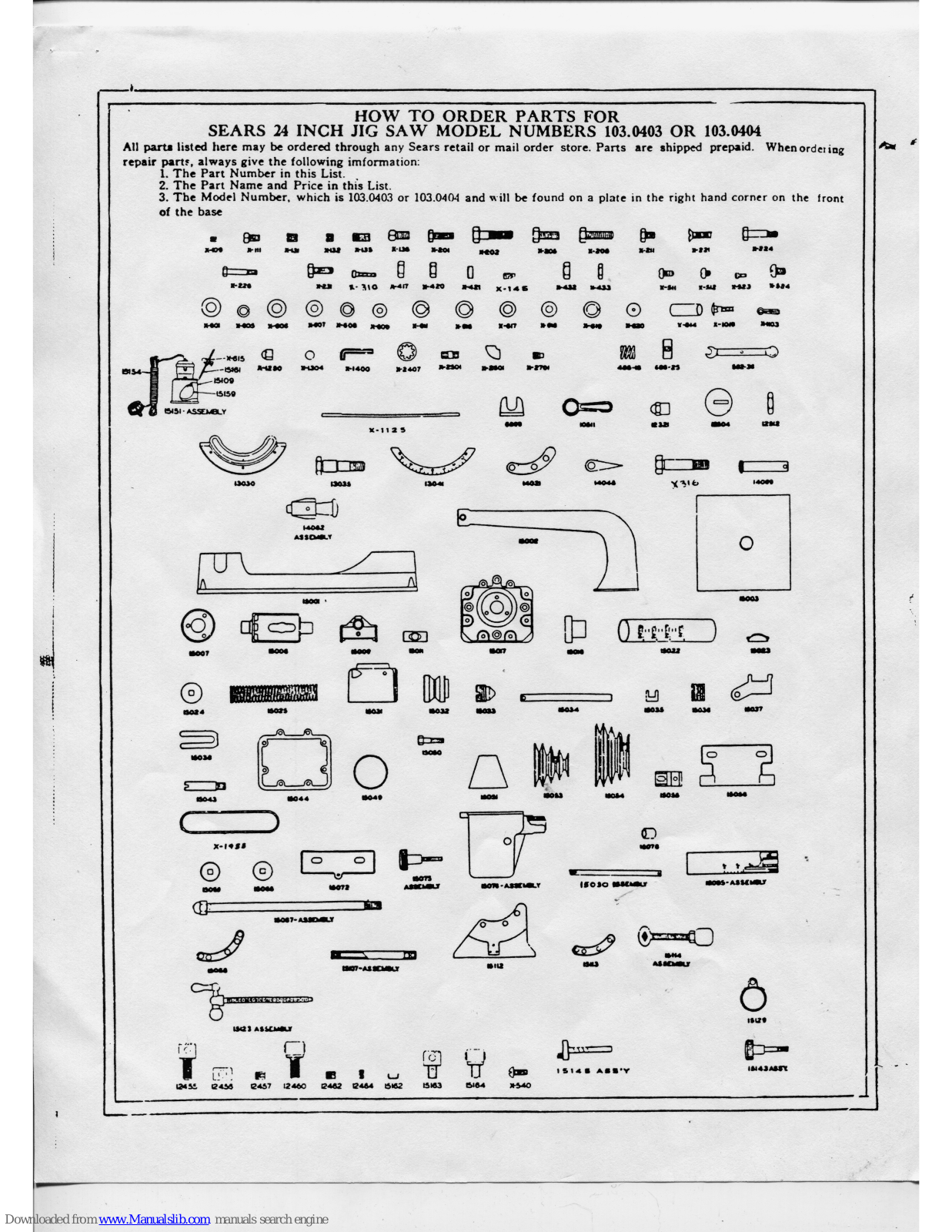
HOW TO ORDER PARTS FOR SEARS 24 INCH JIG SAW MODEL NUMBERS 103.0403 OR 103.0404 All parts listed here may be ordered through any Sears retail or mail order store. Parts are shipped prepaid. When ordering in the listed here may be ordered through any Sears retail or mail order store. Farts are shipped preperty when ordering r parts, always give the following imformation: 1. The Part Number in this List. 2. The Part Name and Price in this List. 3. The Model Number, which is 103.0403 or 103.0404 and will be found on a plate in the right hand corner on the front of the base Anter Bronning -A 0 0 677 X-141 F-224 0 0 A 1 8 ×316 r. 0 ..... 0 00 504J X-1455 ------Jum Т Бю E ISIG -----*540
PARTS LIST
This Sheet is Intended for Instruction and Repair Parts only and is not a Packing Slip. The Parts Shown and Listed may include Accessories Not Necessarily Part of This Tool All Parts Are Shipped Prepaid
All prices are subject to change without notice.
| = | |
|---|---|
| Part | |
| N | Jumb |
| r | um |
| art | Part | Name of Part | |
|---|---|---|---|
| umber | Name of Part | Number | Name of Fait |
| Protractor Clama Pin Spring | 15114 | Screw Assembly | |
| 6 95 | Shaft Coller Assembly | 15123 | Tensioner Screw Crank Assembly . |
| 2-36 | Wrench | 15129 | Tensioner Collar |
| 99 | Motor Support Clip | 15138 | Pump Tube Assembly Complete |
| 511 | Protractor Lock Wrench | 15139 | Crank Case Assembly Complete Includes |
| 321 | Protractor Clamp Nut | Boot and Chuck Less Pulley | |
| 455 | Chuck Housing-Lower | 15143 | Pump Tube Clamp Knob Assembly |
| 456 | Blade Centering Cover | Includes 15141 (1), 15142 (1) | |
| 457 | Socket Head Clamp Screw | 15145 | Pulley Shalt and Crank Assembly |
| 460 | Chuck Assembly-Lower | 15151 | Lamp Assembly Complete |
| 462 | Slotted Head Set Screw | 15154 | Complete Upper Head Assembly (Not |
| 464 | Lower Guide Rod Plug | 15155 | Tiling ) |
| 504 | Table Insert | 15159 | Lamp Bulb |
| 512 | Chuck Jaw Housing Lock Nut | 15161 | Lamn Bracket |
| 030 | Table Protractor Guide Screw Short | 15162 | Upper Guide Tube Spacer |
| 035 | Protractor Scale | 15163 | Chuck Housing-Upper |
| 041 | Table Protractor Clamp, Rear | 15164 | Chuck Assembly-Upper |
| 048 | Mitre Gage Pointer | X-814 | Pulley Shaft Bearing |
| 069 | Protractor Clamp Pin-Rear | X-1125 | Jig Saw Blade-5" Length |
| 082 | Mitre Gage Plunger Assembly | 15 teeth per inch-Purchase from | |
| 001 | Base | division 9 in nearest retail store | |
| 002 | Arm | X-1455 | V Belt 1/2" x 32" - Purchase from Div. 9 |
| 003 | Table | In nearest retail store | |
| 007 | Boot Retainer | X-2407 | BOOL LOCK WASHER & CHARCENTON |
| 6008 | Lower Guide Rod Bracket | IHE | TOLLOWING FARTS ARE STATUS |
| 6009 | Yoke | X 100 | Tonsioner Coller Set Screw 3/16-24x 4 |
| 6011 | Yoke Pin | X 111 | Collar Set Screw 14-20x 7 |
| 5017 | Crank Case Cover |
X-111
X-121 |
Motor Pulley Set Screw 1/4 -20x 1/8 sq. hd. |
| 5018 | Mounting Insulator | X-131 | Driven Pulley Set Screw 5/16-18x 38 |
| 5022 | Pump Tube | X-135 | Driven Pulley Set Screw 5/16-18x 1/4 |
| 5023 | Pump Tube Cap | X-138 | Yoke Set Screw 5/16-18-14 Sq. Hd |
| 024 | Pump Leather | X-146 | Crank Disc Set Screw |
| 025 | Hange Guide Tube Assembly | X-201 | Crank Case and Guide Rod Bracket |
| 5030 | Pump Tube Support | Screw ¼-20-¾ | |
| 5032 | Pump Tube Support Pilot | X-202 | Thrust Roller Guide Support Screw |
| 5033 | Pump Tube Support Pilot Lock Screw | 4-20-1 3 | |
| 5034 | Saw Guide Rod | X-205 | Table Mounting Screw 5/16-18-% |
| 5035 | Thrust Roller Holder Guide | X-208 | Table Support Mounting Screw |
| 5036 | Saw Thrust Roller | 5/10-18-1 Saring Saraw 14-20-76 | |
| 5037 | Thrust Roller Holder | X-211 | Hoto Pail ('lin Screw 14-20-76 |
| 5038 | Hold Down Spring | X-221 | Thrust Roller Holder Guide Screw |
| 5043 | Thrust Roller Pin | A-224 | 1 -20-1 4 |
| 5044 | Crank Case Gasket | Y 228 | Pump Tube Support Pilot Screw |
| 5049 | Boot Spring | || A-220 | 3-16-2 14 |
| 5050 | Protractor Lock Fluiger Housing | ¥-231 | Thrust Roller Holder Sc. 14-20-14 |
| Screw | X-310 | Motor Support Screw 5/16-18x11/2 | |
| 5051 | Boot | X-316 | Table Protractor-Lock Screw 3-24x2 |
| DOD3 | Lig Sew Pulley | X-417 | Motor Support Screw Nut 5/16-18 |
| 5055 | Thrust Roller Holder Support | X-420 | Roller Holder Guide Sc. Nut. 14-20 |
| 5055 | Motor Support | X-421 | Motor Rail Clip Screw Nut 14-20 |
| 5050 | Pump Spring Guide | X-432 | Protractor Guide Screw Nut #1-24 |
| 5055 | Pumn Leather Washer | X-433 | Protractor Scale Nut #4-40 |
| 5072 | Motor Adjusting Bracket | X-511 | Pump Leather Retaining Screw |
| 5075 | Saw Guide Rod Lock Knob Assembly | # 10-24x % | |
| 5076 | Crank Case Assembly Includes 15004 | X-512 | Protractor Pointer Screw #8-5207 |
| X-814 (1) | X-523 | Lamp Bracket Screw # 4_40x 30 | |
| 5078 | Motor Support Sleeve | X-524 | Linear Cuide Tube Specer Sore |
| 5085 | Pump Tube Assembly | || X-540 | C 20-216 |
| 5087 | Arm Stud Assembly | V cost | Plain Wesher 5/16 Std |
| 5088 | Protractor Guide-Kear | X-601 | Lock Washer & Std |
| 5107 | Lower Cuide Rod Assembly | X-605 | Plain Washer % Std. |
| 15109 | Lamp Shade | X-000 | Plain Washer 4 Std. |
| 5112 | Table Support | A-001 | (Continued on next page) |
| 5113 | Protractor Guide-Front | 11 | |

OPERATING INSTRUCTIONS FOR 24 INCH JIG SAW
To prepare for shipping, the oil has been removed from this tool. Do not run until refilled with a good grado of oil similar to S.A.E. No. 30. To refill, remove the pipe plug from filler pipe in front of crank case and pour in SLIGHTLY LESS THAN ONE PINT OF OIL.
THIS FILLING OF OIL SHOULD LAST INDEFINITELY, BUT IF MORE OIL IS ADDED, POUR IN ENOUGH TO HAVE IT JUST VISIBLE AT THE BOITOM OF THE FILLER PIPE.
Any oil in excess of the above amount will be wasted as same will pass from crank case either through breather hole or vents around piston rod until required level is reached. The crank case mechanism and main bearing are lubricated by means of an oil pressure system. The pressure is produced by a simple pump arrangement in combination with the mechanism in crank case which pumps and forces the oil from the bottom of the crank case to all parts requiring lubrication in the crank case.
The square upper pump piston rod should be oiled or greased and a few drops of oil should be applied through the hole in the pump tube cap occasionally.
Periodic greasing of the table trunnions is recommended.
REASSEMBLY INSTRUCTIONS
This jig saw has once been completely assembled at the factory and to avoid breakage through rough handling while in transit the table has been removed.
Looking at the under side of this table you will note that one pair of trunnion bosses is close to one edge of the table. To reassemble table, n'ace the table on the trunnions with these bosses toward the back.
The four mounting screws are in the cloth bag. Place the plain washer next to the trunnion boss, then the lock washer before tightening screws.
The blade has been pushed up into the upper chuck to avoid breakage.
CAUTION. For shipping purposes the upper pump tube assembly has been lowered and the clamp bolt tight-
To raise or turn this tube loosen the clamp bolt and move the assembly by hand.
Do not turn pump tube with WRENCII OR PLIERS.
SPEEDS
The large pulley is mounted with large diameter next to the crank case and the small pulley is mounted on a 1750 R.P.M. motor with the small diameter adjacent to the motor. This will give approximate speeds of 1750— 1284—926 and 657. 926 and 1284 are the recommended speeds. A 1/3 horsepower motor is recommended for this saw.
PULLEY ON CRANK CASE MUST RUN IN DIRECTION INDICATED BY ARROW SHOWN ON OUT-SIDE OF CRANK CASE SHAFT BEARING HOUSING.
MOTOR MOUNTING
The motor mounting is in two parts, the front end being the conventional floating type pivoted in adjustable clips. The rear part has an adjusting screw so weight of motor can be relieved from the belt and bearings.
PUMP MECHANISM
The upper guide tube and pump mechanism is mounted in a housing which is fastened in the overarm by means of taper pointed screws which register against the angular surfaces of a groove in a pivot pilot which is bolted to the housing.
Loosening the screws permits the entire a sembly to be turned radially. Removing the screws permits the removal of the assembly. Air for blowing dust away from the work is provided through a tube concealed in the pump tube. Additional air is exhausted through chuck jaws in upper guide tube.
The graduations on the pump tube signify the length of saw blades and the pounds pressure of the spring at the top of the stroke. For example, when using a 5" blade the 5"-6½ # mark should register at the top edge of housing.

For radial alignment the vertical line through graduation on the tube must register with the pointer on support housing located 45° to the right from the front.
Fasten the tube securely in this position. For ripping turn the entire pump tube assembly and saw blade roller guide 90° to the right so that vertical line on the tube lines up with pointer.
FORM 109-2
- 4 41.V.
JIG SAW WITH TENSIONER_MODEL 103.0404 ONLY
A blade tensioner is provided so that correct tension can be obtained when using various sizes of blades. Tension can be varied with blade in place and while machine is in operation.
Improper tension will cause vibration which will disappear when correct point is reached.
To increase or decrease the tension of the saw blade. loosen pump tube clamp screw and turn ball crank to the right or left. Lock clamp screw when desired tension is reached.
SAW BLADE ROLLER GUIDE AND HOLD DOWN SPRING
To move roller guide toward and away from the saw loosen bolt A in Fig. 2 and slide the assembly to the desired position. To move the roller laterally loosen the bolt B and slide the roller and hold down spring to the groove selected.
TO CHUCK SAW BLADES
1 Place blade in the lower chuck and tighten socket head clamp screw.
2. Turn drive pulley until the lower chuck is raised to its highest position.
3. Loosen pump tube clamp screw and set pump tube at proper position for length of saw blade being insert-
4. While in this position insert blade in upper chuck by pulling down upper chuck slightly and tightening the clamp screw.
5. Turn pullcy over by hand to make certain that the spring in head is under tension at the top of stroke. Failure to observe this condition will result in poundin
Install blade with cutting teeth pointing downward. Blade will work best with cutting edge square with table.
Maximum thickness to cut with 5" blade is "4". For thicker material use longer blades and raise nump tube. Blades up to 10" long can be used without changing the setting for 5" blades, but the blade must be put through the upper chuck starting from below the table through the table insert.
TH INC.
The round shank files to be used in this machine, listed in the Sears Power Tool Catalog, are held in the lower chuck. To insert a file remove the chuck screws and lift off the blade centering cap. Place file in chuck and fasten securely by tightening slotted set screw only against the file shank. The table may be tilted to file angles or to correct for any bow in the file.
TARLE
To tilt the table unlock the front trunnion by pulling the lever wrench on to hexagon nut. Loosen. Pull plunger ston for important angular positions, intermediate angles must be lined up with the pointer. Relock with lever wrench on nut. The pointer on the graduated protractor is adjustable if necessary to correct any error on protractor with the table top.
OVERARM
Marks on the top of the overarm and pump tube housing at the joint permits the entire housing assembly to be returned to its normal alignment.
Overarm is pivoted at the rear of the base so it can be swung to the right or left or entirely removed by loosening the stud which clamps it to the base. The distance from the center of the saw to the inside of arm permite full 24" cute
At the overarm pivot joint at the rear end of the base a mark determines the normal sawing alignment of the arm.
RUBBER MOUNTING INSULATORS
Place one in each cored recess on the inside corners of base. These rubbers will help to level your saw and deaden sounds which may be transmitted through your mounting stand or bench. SABRE SAWING ACCESSORY
Loosen blade in upper chuck. Remove roller guide and hold-down spring by taking out the screw at the bottom. Loosen acorn nut on rear of upper arm and move arm to either side. Tilt table to the left 45°. With long screw through slot, line up roller guide with small support casting (Part No. 15055) included with extra parts. Fasten this assembly to boss underneath the table and behind the blade. Return table to horizontal position.
ADDITIONAL ACCESSORIES AVAILABLE FENCE AND TABLE EXTENSIONS
Provision is made in the ends of the table for attaching fence guide, and extensions for the front and sides I the table. These extensions increase the table size from 14-3/16" square to 18-3/16" x 25-4.". The table space in front of the saw is increased from 7-4" to 11-14".


 Loading...