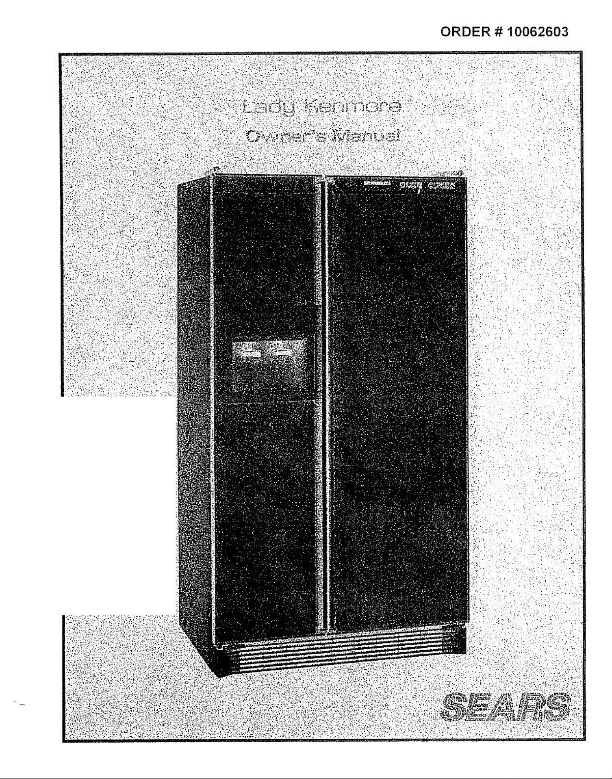
Page 1
ORDER # 10062603
_ ?_- i 'i_!i_ _i ¸ ii!,: iii_ _! _ii_ ¸ i .... =
Page 2
Sears Service
ts At Your Service
Your Kenmore has added value when
you consider that Sears has nationwide
service units staffed by Sears-trained
technicians. _..professional technicians
specifically trained to service SEARS
appliances, having the parts, tools and
equipment to insure that we meet our
pledge to you. "We Service What
We Seli."
ADD TO THE VALUE OF YOUR
KENMORE, BUY A SEARS
MAINTENANCE AGREEMENT
Sears Kenmore refrigerators are
designed, built and tested for' years of
dependable use_ Yet any modern
appliance may need service from time
to time. The Sears warran_ plus the
Sears maintenance agreement give
protection from unexpected repair bills
Contact your salesman or nearest ser-
vice center for details..
For future use, please record
the model number, serial
number and the date you
purchased your Kenmore
refrigerator in the spaces
provided below:
Model Number
Serial Number__
Date Purchased
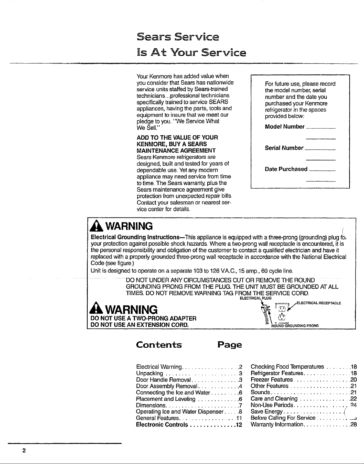
WARNING _r
Electrical Grounding Instructions--This appliance is equipped with a three-prong (grounding) plug fo,
your' protection against possible shock hazards. Where a two-prong walI receptacle is encountered, it is
the personal responsibility and obligation of the customer to contact a qualified electrician and have it
replaced with a properly grounded three-prong wal! receptacle in accordance with the National Electrical
Code (see figure.)
Unit is designed to operate on a separate 103 to 126 VA_C., 15 amp., 60 cycle line.
DO NOT UNDER ANY CIRCUMSTANCES CUT OR REMOVE THE ROUND
GROUNDING PRONG FROM THE PLUG. THE UNIT MUST BE GROUNDED ATALL
TIMES. DO NOT REMOVE WARNING TAG FROM THE SERVICE CORD.
DO NOT USE A TWO-PRONG ADAPTER }I_\ _'_'_
DO NOT USE AN EXTENSION CORD. _O_UND G_:_%OUNDING P_ONG
Contents
Electrical Warning .................... 2
Unpacking ........................... 3
Door Handle Removal ................ 3
Door Assembly Removal .............. 4
Connecting the Ice and Water .......... 6
Placement and Leveling ................. 6
Dimensions ......................... 7
Operating Ice and Water Dispenser .... 8
Genera{ Features .................... 11
Electronic Controls .............. 12
Page
ELECTRICAL PLUG
"_'r" EL£CTRICAL RECEPTACLE
TV
Checking Food Temperatures ........ 18
Refrigerator Features ................... 18
Freezer Features .................... 20
Other Features ..................... 21
Sounds ........................... 21
Care and Cleaning ....................
Non-Use Periods ..................... _4
Save Energy ....................... (
Before Calling For' Service ........... J
Warranty Information ............... 28
Page 3
packing and Door Handtle Removal
CAUTION
To Avoid The Risk Of Personal
Injury, Use Caution In Unpacking,
Handling, Removing, Installing
and Cleaning All Parts Of Product
Which May Have Sharp Edges.
ACAUTION
To Avoid The Risk Of Personal
Injury, Wear Protective Hand
Covering.
Remove all tape and packing material
To remove tape residue, touch a portion
of the tape to the residue and lift it off If
adhesive residue still remains, try clean-
ing the sticky area with a clean cloth
soaked in mild dish washing soap. Wipe
area clean_
if the wood base is still attached, have
snmeone help you tilt the unit onto its
k, placing a sturdy support under-
._th. Remove the mounting bolts from
the base and discard bolts and wood
base,
IMPORTANT! Do not leave the cabinet
on its back longer than it takes to
remove the wooden base and do not
connect the power cord until after all the
inside packing has been removed and
the cabinet has been leveled for proper
operation.
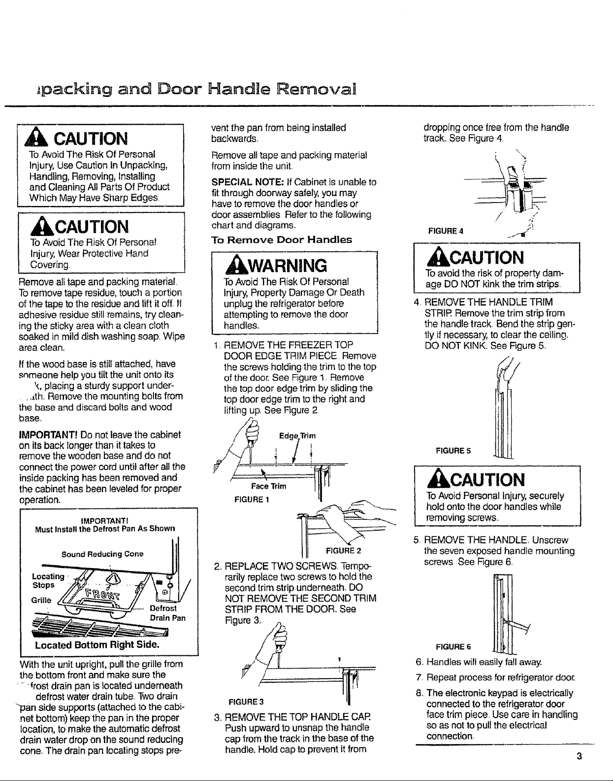
IMPORTANTI
Must Install the Defrost Pan As Shown
Sound Reducing Cone
Locating
Stops
Grille
Defrost
n Pan
vent the pan from being installed
backwards.
Remove all tape and packing material
from inside the unit
SPECIAL NOTE: If Cabinet is unable to
fit through doorway safely, you may
have to remove the door handles or
door assemblies Refer to the following
chart and diagrams.
To Remove Door Handles
WARNING
To Avoid The Risk Of Personal
Injury, Property Damage Or Death
unplug the refrigerator before
attempting to remove the door
handle&
REMOVE THE FREEZER TOP
DOOR EDGE TRIM PIECE. Remove
the screws holding the trim to the top
of the door. See Rgure 1, Remove
the top door edge trim by sliding the
top door edge trim to the right and
lifting up. See Figure 2
Trim
I
Face Trim
FIGURE 1
FIGURE 2
2o REPLACE TWO SCREWS. Tempo-
rarily replace two screws to hold the
second trim strip underneath. DO
NOT REMOVE THE SECOND TRIM
STRIP FROM THE DOOR_ See
Figure 3o
dropping once free from the handle
track° See Hgure 4.
FIGURE 4 __"
, CAUTION
To avoid the risk of property dam-
age DO NOT kink the trim strips.
REMOVE THE HANDLE TRIM
STRIR Remove the trim strip from
the handle track. Bend the strip gen-
tly if necessary, to clear the ceiling.
DO NOT KINK. See Figure 5.
FIGURE 5 i _/
ACAUTION
To Avoid Personal Injury, securely
hold onto the door handles while
removing screws.
5 REMOVE THE HANDLE, Unscrew
the seven exposed handle mounting
screws See Rgure 6.
Located Bottom Right Side.
With the unit upright, pull the grille from
the bottom front and make sure the
' "frost drain pan is located underneath
defrost water drain tube. Two drain
'_'pan side supports (attached to the cabF
net bottom) keep the pan in the proper
location, to make the automatic defrost
drain water drop on the sound reducing
cone. The drain pan locating stops pre-
FIGURE 3
3. REMOVE THE TOP HANDLE CAR
Push upward to unsnap the handle
cap from the track in the base of the
handte. Hold cap to prevent it from
FIGURE 6
6. Handles wilt easily fall away
7. Repeat process for refrigerator door.
8o The electronic keypad is electrically
connected to the refrigerator door
face trim piece. Use care in handling
so as not to pull the electrical
connection
Page 4
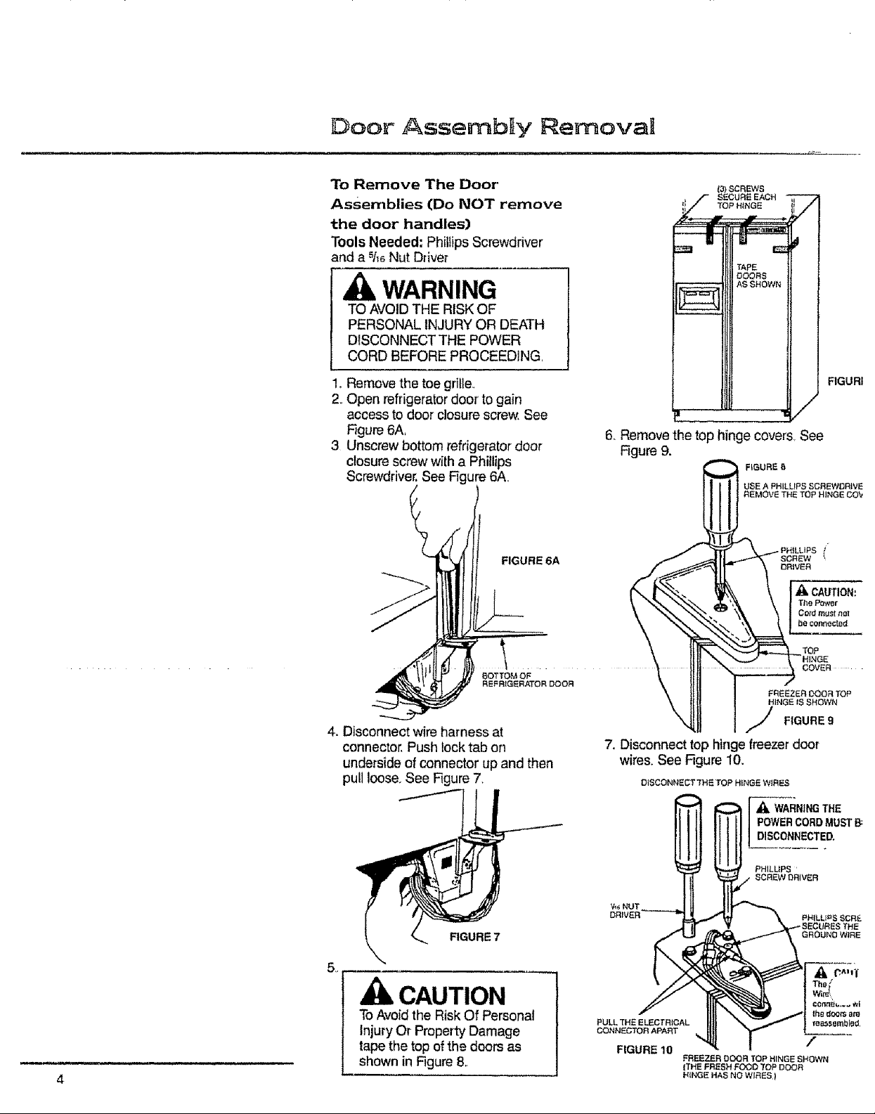
Door AssemblIy Removal
To Remove The Door'
Assemblies (Do NOT remove
the door handles)
Tools Needed; Phil{ips Screwdriver
and a 51,_ Nut Driver
WARNING
TO AVOID THE RISK OF
PERSONAL INJURY OR DEATH
DISCONNECT THE POWER
CORD BEFORE PROCEEDING.
1_ Remove the toe grille.
2. Open refrigerator door' to gain
access to door closure screw, See
Figure 6A,
3 Unscrew bottom refrigerator door
closure screw with a Phillips
Screwdriver, See Figure 6A.
FIGURE 6A
(3) SCREWS
SECURE EACH
t[ TOP HINGE
6,, Remove the top hinge covers, See
Figure 9.
F_GURB 8
USE A PHILUPS SCREWDR}VE
REMOVE THE TOP HINGE COY
SCREW I
DRIVER
CAUTION:
The Power
Ce_d must nut
be connected
FIGURI
TOP
BOTTOM OF
REFR}GERATOR DOOR
4. Disconnect wire harness at
connector, Push lock tab on
underside of connector up and then
pull loose. See Figure 7.
FIGURE 7
,,
7. Disconnect top hinge freezer door
wires. See Figure 10..
DISCONNECT THE TOP HINGE WIRES
POWER CORD MUST B:
_k WARNING THE
DISCONNECTED.
PH]LUPS
SCREW DRIVER
COVER
FREEZER DOOR TOP
HINGE IS SHOWN
FIGURE 9
PH{LL}_$ ECRU.
GROUND WiRE
CAUTION
To Avoid the Risk Of Personal
Injury Or Property Damage
tape the top of the doors as
shown in Figure &
4
Page 5
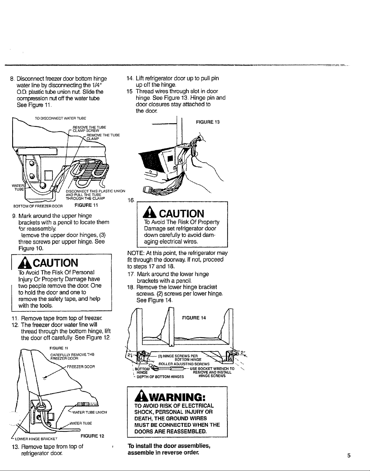
8. Disconnect freezer door bottom hinge
water line by disconnecting the 1/4"
OO_ plastic tube union nut, Slide the
compression nut off the water tube
See Figure 11.
TO DISCONNECT WATER TUBE
REMOVE THE TUBE
" CLAMP SCREW
REMOVI
DISCONNECT TRIS PLASTIC UN_ON
AND PULL THE TUBE
THROUGH THE CLAMP
FIGURE 11
9. Mark around the upper hinge
brackets with a pencil to locate them
{or reassembly.
{emove the upper door hinges, (3)
three screws per upper hinge. See
F_gure 10.
[ CAUTmON
To Avoid The Risk Of Personal
injury Or Property Damage have
two peop{e remove the door,, One
to hold the door and one to
remove the safety tape, and help
with the tools.
14. Lift refrigerator door up to pull pin
up off the hinge.
15 Thread wires through slot in door
hinge See Figure 13 Hinge pin and
door closures stay attached to
the door,
FIGURE 13
16.
CAUTION
To Avoid The Risk Of Property
Damage set refrigerator door
down carefully to avoid dam-
aging electrical wires.
NOTE: At this point, the refrigerator may
fit through the doorway, If not, proceed
to steps 17 and 18.
17 Mark around the lower hinge
brackets with a pencil.
18. Remove the lower hinge bracket
screws. (2) screws per lower hinge°
See Figure 14.
11, Remove tape from top of freezer.
12. The freezer door water _ine will
thread through the bottom hinge, lift
the door off carefully See Figure 12
FIGURE It
FREEZERDOOR
R TUBE UNION
LOWER HINGE BRACKE T
FIGURE 12
13. Remove tape from top of
refrigerator door.
FIGURE 14
OCKET WRENCH TO \_
REMOVE AND iNSTALL
HINGE SCREWS
IkWARNING:
TO AVOID RISK OF ELECTRICAL
SHOCK, PERSONAL INJURY OR
DEATH, THE GROUND WIRES
MUST BE CONNECTED WHEN THE
DOORS ARE REASSEMBLED,
'To install the door assemblies,
assemble in reverse order,
\4
Page 6
Connect the Ice and Water'
System to Cold Water
Supply.
Refer to the instructions on the back of
the cabinet.
Pilacement and Leveling
i,i i I,IIH
, CAUTION:
To avoid cross threading and
water ieaks, you must start alt the
water tube fittings several turns by
hand before tightening with
wrenches. DO NOT OVER-
TIGHTEN. Also be sure to double
check for water leaks after turning
on the water pressure to the
refrigerator.
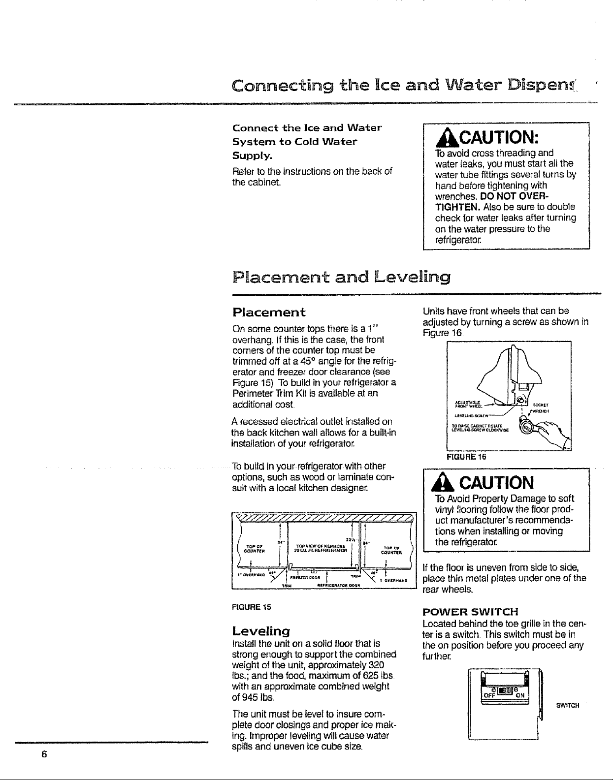
Placement
On some counter tops there is a 1"
overhang If this is the case, the front
corners of the counter top must be
trimmed off at a 45 ° angle for the refrig-
erator and freezer door clearance (see
Figure 15) To build in your refrigerator a
Perimeter Trim Kit is available at an
additional cost.
A recessed electrical outlet installed on
the back kitchen wall atfows for a built-in
installation of your refrigerator.
To build in your refrigerator with other
options, such as wood or laminate con-
sult with a local kitchen designer.
) .......... ,,!,..ll!,. ........... I
Units have front wheets that can be
adjusted by turning a screw as shown in
Figure 16.
CAUTION
To Avoid Property Damage to soft
vinyl floodng follow the floor prod-
uct manufacturer's recommenda-
tions when installing or moving
the refrigerator.
If the floor is uneven from side to side,
place thin metal plates under one of the
rear wheels.
FIGURE 15
Leveling
Install the unit on a solid floor that is
strong enough to support the combined
weight of the unit, approximately 320
tbs.; and the food, maximum of 625 ibs
with an approximate combined weight
of 945 tbs.
]'he unit must be level to insure corn-
plete door closings and proper ice mak-
ing. Improper leveling will cause water
spills and uneven ice cube size.
POWER SWITCH
Located behind the toe grille in the cen-
ter is a switch. This switch must be in
the on position before you proceed any
further.
SWITCH
Page 7
_IMENSHONS
i
4.,_
68 3/4 '_
"A" *'B" "D"
ICABINET I FRZ DOOR REF DOOR TO
MODEL WIDTH OPEN 90 ° OPEN 90 ° HANDLE
"C" OC* BACK
2o I 3_, i 3g_ 4_,/o 27_
"Ouler Case
t" Must be installed 1:Y4" from side wails for 90 ° door opening,
1"
Hinge
Cover
67½
{_E _
OC" BACK
TO CAB
FRONT
23_/z
Page 8
Operating the Ice and VVater Dispense
water supply system as well as the
k,CAUTION:
To Avoid the Possibility of Per-
sonal Injury, Never Attempt to
Operate the lce Dispenser with
the Door Open,
Separate dispenser bars control the
release of ice cubes and water, They are
located in a recessed alcove for safety
and convenience The dispenser bars
are sculptured to fit the contours of an
ordinary drinking glass Depress the
appropriate dispenser bar to activate
the dispensing mechanism
Small spills wil! be caught in the sump
area below the dispenser, The sump
cover gdlle is easily removed for
cleaning.
NOTE: There is no drain in the sump
so water should not purposely be
poured into it.
Do not add ice to ice bin=
Do not try to speed ice dispensing by
adding cubes of ice that you may have
purchased or made in some other way.
The unit has been "matched" to the
automatic ice maker and will not oper-
ate properly with different shaped or
sized cubes.
Water Dispenser
To operate, press glass against the
water dispenser bar. Releasing pres-
sure shuts the water off,
After the unit is connected to an active
household cold water line, it is advisable
to fil_ and throw out the first 10-14
glasses of water This wilt cleanse the
lines of impudtie&
Water taste and odor.
There are many variables which can
affect the taste and odor properties of
the water that is being dispensed from
your Ice and Water model such as:
1 Iron and other mineral deposits nor-
mally found in water.
2. Type of tubing (copper, galvanized,
plastic, etc.) used in the household
type of tubing used to connect your
unit to your household water supply
3 Is the water "fresh" or has it been
left standing unused in the storage
reservoir and/or water supply line for
any length of time?
To minimize taste and odor problems, it
is recommended that the following
steps be taken:
l Thoroughly rinse out the system after
it has been connected to the house-
hold water supply. This can be
accomplished by throwing away the
first 10-14 eight-ounce glasses of
water that are obtained from the unit
2. If the water dispensing system is not
used frequently, the entire water res-
ervoir and system should be flushed
This wilt ensure a fresh supply of
water at all times
if the above suggestions do not entirely
eliminate an undesirable taste or odor
condition in your water, your problem
most likely a water problem It is recom
mended that you contact your Ioca!
water treatment company for its spe-
cialized kind of help in solving your
problem°
How The Water Dispenser
Works
The water reservoir is located in the
refrigerator behind the crisper pan° The
water line to the dispenser bar is routed
in a special way to prevent freeze-ups.
The water dispensing lever energizes
the water line solenoid valve to add
water to the water reservoir.
Page 9
The water is forced by household water
pressure through the tubing and out the
water dispenser.
This water is cooled in the water reser-
voir. Some water remains in the water
line to the dispenser, causing the first
glass of water to be somewhat warmer
than the folfowing glasses
Ice Dispenser
Overload, if you hold the dispenser bar
in the ON position for approximately 4-5
minutes, the dispenser motor may trip
out on overload This could occur if you
were trying to fill a large container with
ice, The overload will reset automatica!ly
in approximately 3 minutes, after which
ice can again be dispensed.
IMPORTANT! UNDER NO CIRCUM-
STANCE SHOULD YOU USE AN ICE
PICK OR SIMILAR SHARP INSTRU-
MENT TO BREAK THE ICE To do this
could cause damage to the ice bin
and/or ice auger.
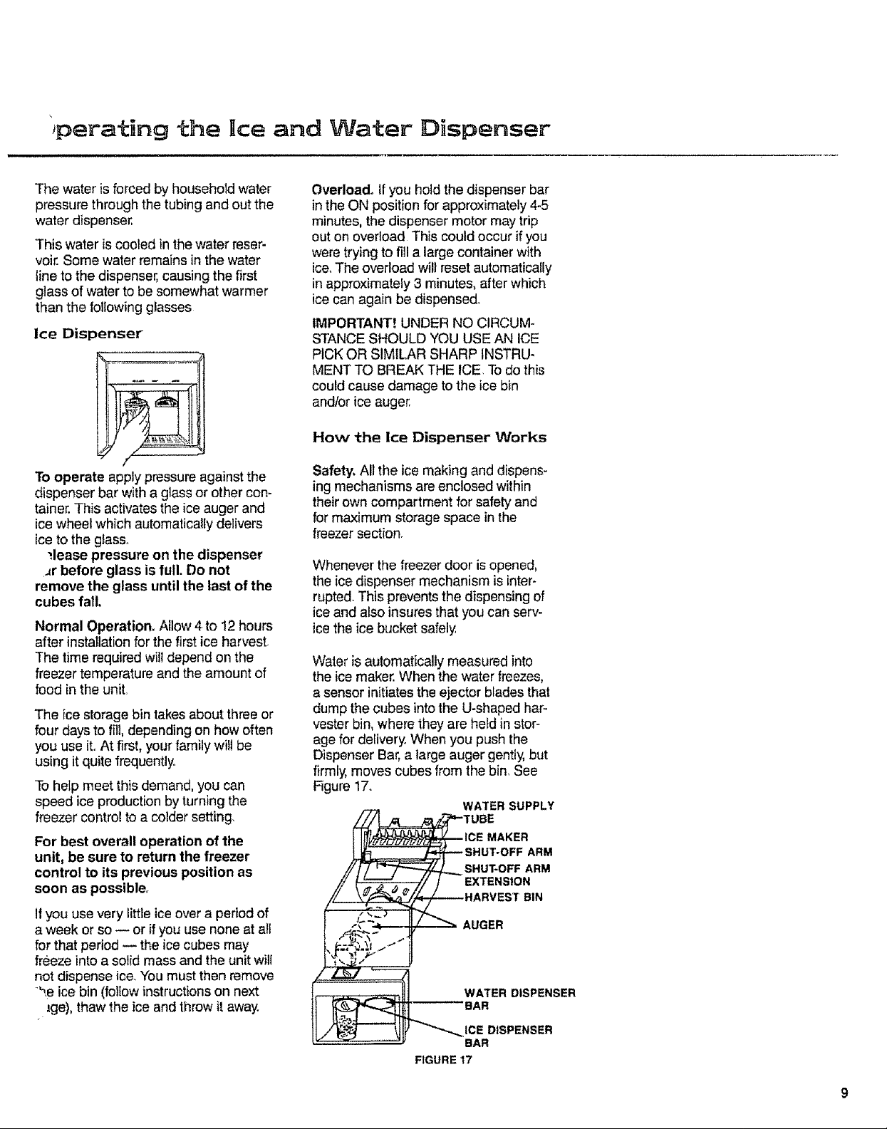
How the Ice Dispenser Works
To operate apply pressure against the
dispenser bar with a glass or other con-
tainer. This activates the ice auger and
ice wheel which automatically delivers
ice to the glass.
;lease pressure on the dispenser
_r before glass is full. Do not
remove the glass until the last of the
cubes fail.
Normal Operation. Allow 4 to 12 hours
after installation for the first ice harvest
The time required will depend on the
freezer temperature and the amount of
food in the unit
The ice storage bin takes about three or
four days to fill, depending on how often
you use iL At first, your family will be
using it quite frequently
To help meet this demand, you can
speed ice production by turning the
freezer control to a colder setting.
For best overall operation of the
unit, be sure to return the freezer
control to its previous position as
soon as possibler
I1 you use very littte ice over a period of
a week or so -- or if you use none at all
for that period -- the ice cubes may
freeze into a solid mass and the unit wilt
not dispense ice. You must then remove
',e ice bin (follow instructions on next
lge), thaw the ice and throw it away.
Safety. All the ice making and dispens-
ing mechanisms are enclosed within
their own compartment for safety and
for maximum storage space in the
freezer section.
Whenever the freezer door is opened,
the ice dispenser mechanism is inter-
rupted. This prevents the dispensing of
ice and also insures that you can serv-
ice the ice bucket safely
Water is automatically measured into
the ice maker. When the water freezes,
a sensor initiates the ejector blades that
dump the cubes into the U-shaped harm
vester bin, where they are held in stor-
age for delivery When you push the
Dispenser Bar, a large auger gently, but
firmly, moves cubes from the bin, See
Figure 17.
WATER SUPPLY
MAKER
SHUT-OFF ARM
EXTENSION
BIN
AUGER
WATER DISPENSER
BAR
_ICE DISPENSER
BAR
FIGURE17
9
Page 10
Servicing The Ice Dispenser
2 To stop ice production or to remove
the ice bin: take hold of wire arm
Certain conditions witt require you to
service the ice maker and dispenser.
The unit has been designed so that you
can do such servicing with a minimum
of effort.
near black housing, and lift up, There
will be an audible "click" when ice
maker shuts off. The wire arm stays
in the upper' position, (See Fig, 19,)
As long as the arm is in this position,
ice wilt not be made. The unit will
Cold dry air has to circulate in the
freezer to maintain a safe freezing tem-
continue to dispense cubes from the
ice bin until oil have been used_
perature. Thus. cubes stored in the bin
will tend to evaporate and flow together
if not used regularly
You should remove the bin and
empty the contents:
= After the first few harvests of ice have
been made by a newly installed unit,
This will allow any impurities in the
line to be flushed out,
SHUT-OFF ARM
If you are going to be gone for longer
than a week_ Raise the ice maker
TO STOP THE
ICE t,_AKER FIGURE 19
shut-off arm to stop ice production
and prevent the cubes from freezing
into a mass around the ice auger.
To remove ice bin assembly: Lift up •
the ice bin assembly _/4", then pull out!
if the ice cubes become frozen to '1"he Automatic Shut-off stops ice
each other and around the ice auger, making by raising the control arm when
If the ice cubes become frozen the ice bin is removed. (See Fig. 20,)
together on the back ledge of the ice
bin, Periodic cleaning of the ice bin
may alleviate this occurrence_ Clean
with warm water and dry before
replacing bin. Do not use an ice pick
to break apart ice,
ice maker control arm. The wire con-
trol arm on the automatic ice maker has
2 functions:
10
1_ Normal Operation: the wire arm is
in the down position; ice will be
made, See Fig, 18.
\ FIGURE 18
AU'FOMATIC SNUT-OFF ARM
EXTENSION
tN THE OFF FOSIT_ON fWHEN
THE =CE STORAG_ SIN HAS
THE AUTOMATIC SHUT*OFF tS SHOWN
SE_N REMOWO) FIGURE 20
AUTOMATIC SHUT-OFF
Page 11
eneran Features
Removable Door Dikes
Removable Freezer
Door Shelf
Ice and Water
Dispenser
Adjustable Freezer,
Door Shelves
Ice Bin
First Freeze Shelf
Egg Storage
Adjustable
Refrigerator Glass Shelves
///
Dairy and
Handi Bin
, Adjustable
Refrigerator
Door Shelves
Drawer
Adjustable Humidl
Drawer Controls
!
Glide-out
Basket
"Features may vary from model to model Your refrigerator may not have all of
the features shown.
Toe Grille
Defrost Drain Pan
and Condenser
(Behind Toe Grille)
Adjustable Humidity
Controlled Crispers
11
Page 12
. • . ...... . , ., . . .
" . • - _ . i _ -
E- ,
BEFORE YOU GET S?ARTED.:' ....
in, the temperature ir_d_cato_lights,wlii " " " "
t_tink. P_'ess tile ELECTRONIC.TEM;, -
PERATURE CONTROL Or ACARM
C[.EA B pad,. • "
.k
• POWER SWITCH ' "
" . -•*••"., / r•:" - • .. ,•/_. •. _-_- "..'.
L_ocatecJ behind the {oe grilie in the ten-
tel is a_:switcl_: This SWiLch must b6 in;
" theen p0sition befo_'e you proceed any
NOTE: The alarm may go 0if in (2) two fur ther - :
l!ash, if the refrigerator and freezer have t
hours and the High Temp indicator iighl !
i Oo! lJeeiTcdole d to:the proper tempera-
ture. Deactivate alarm by p_essing the _
ALARM CLEAR pad.
- [ \. .;" : "
Page 13
lect:ron c Con±rol s
THERMOSTATIC REFRIGERATOR CONTROL
An electronic thermostatic sensor mea-
sures refrigerator air temperatures con-
stantly and automatically lets in more
cold a}r if temperatures rise as tittle as
1112 ° F from your setting
PROGRAMMING YOUR REFRIGERATOR
TEMPERATURE SETTINGS
With the Electronic Control, you can
precisely control the temperature in the
refrigerator and freezer sections without
even opening the doors.. The freezer
temperature and the refrigerator tem-
"erature may be changed independent
one another, The temperature of
To Set Or Change The Temperature in The Refrigerator
The Control has nine settings, from '1'
(the warmest) to '9' (the coldest), The
best food storage temperature is in the
38 ° to 40°F range. Start by program-
ming your controls as foIiows:
1. Press the START pad (ELECTRONIC
TEMPERATURE CONTROL).
2. Press the REF TEMP pad. This tells
the control panel you want to set the
each can be set at one of nine tempera-
ture levels. One (1) being the warmest
and nine (9) the coldest.. When chang-
ing the temperature, the temperature
indicator Dights will be on. The indicator
lights will tell you whether the freezer or
refrigerator temperature is being
changed and what level the tempera-
ture is currently at.
3_
The starting temperature setting in
the refrigerator is level 5.
4.
Press the WARMER pad or COLDER
pad to raise or lower the temperature
setting one level at a time° Continue
to hell the WARMER pad or
COLDER pad down to raise or Iower
the temperature more than one level
at a time
temperature in the refrigerator.
+
+
or
or
= Temperature Setting
Raises Or Lowers
One Level At A Time
+
or
+ +
Load food in the refrigerator, Place a
thermometer in a glass of water in
the middle of the refrigerator section,
making sure that air can flow around
it. (This will be used later to check
food temperatures) Alter the unit is
Lowers Temperature
t_let_ooi_Qt w _
C0nlinoe to Ptes_ Down
= Setting More Than
One Level At A Time
Raises Temperature
= Setting More Than
co_i_ _o P_ oow_ One Level At A Time
installed, allow 24 hours for the refrig-
erator to cool Check food tempera-
ture as instructed on page 18 Adjust
the control as needed, one level at
a time.
t3
Page 14
Electronic Controls
To Set Or Change The Temperature
The control has nine settings, from '1' 3
(the warmest) to '9' (the coldest) The
best food storage temperature is in the 4
0 ° to + 2 ° F range Start by program-
ming your controls as follows:
1 Press the START pad (ELECTRONIC
TEMPERATURE CONTROL)
2 Press the FRZ TEMP pad This tells
the control panel you want to set the
In The Freezer
The starting temperature selling in
the freezer is level 5
Press the WARMER pad or COLDER
pad to raise or' lower the temperature
setting one level at a time. Continue
to hold the WARMER pad or
COLDER pad down to raise or lower
the temperature more than one tevet
at a time
temperature in the freezer.
Raises Or Lowers
+
+
or
--- Temperature Setting
One Leve] At A Time
or
Lowers Temperature
+
+
Cont*t_t_e to Pm_; OOwt_
or
-- Setting More Than
One Level At A Time
Raises Temperature
+
CQ_I_t_U_, lo Pto_ Oowf_
= Setting More Than
One Level At A Time
5 Load food in the freezer. Allow 24 period check food ternperatur@ as
h0urs for the freezer to cooi afier the instructed on page 18, Adjust the
unit is installed, before checking food control as needed, one level at
temperatures After the 24 hour a time.
14
VACATION MODE
The Vacation Mode is ideal for when
you wilt be away from your home for an
extended amount of time, but still wish
to preserve the food in your refrigerator.
To Start The VACATION Mode
1 Press the START pad (ELECTRONIC
TEMPERATURE CONTROL)
= Vacation Indicator Light Will Come On Indicating
Vacation Mode is Now On
To Cancel The VACATION Mode
1 Press the START pad (ELECTRONIC
TEMPERATURE CONTROL),
2 Press the VACATION pad again° OR
+ Or'
During this mode the refrigerator will
defrost iess often, saving energy
and money
2 Press the VACATION pad The vaca-
tion indicator light will come on
acknowledging your command
3, Open either the refrigerator or
freezer door.
= Cancel Vacation Mode
O_nD_r
Page 15
Electronic Controls i , ' ,
_MAX REF MODE
During th s mode, the refrigerator tem-
perature is lowered to the coldest level
for ten (10)hours; Ideal if you like colder
chil{ed drinks or have added a lot of
rio Start The,MAXREF Mode
L
1. Press the STAR] • pad (ELECTRONIC
TEMPERATURE CONTROL).
Indicator Light Wilt Come On
---- Indicating The Control Panel
Has Understood Your Command
warm food, After the len (10) hou¢time
period the refrigerator temperature wilt
return to the previous temperature setting
2, Press the MAX REF pad. "[he MAX
R EF indicator light wilI come on
acknow]edging your command,
• • _ , .
To Cancel The MAX REF Mode
!, Press tt_e START pad (ELECTRONIC
TEMPERATURE CONTROL),
2 Press the MAX REF pad again,
, Will automatically
P , g ,. ,:
•, after (10) ten hours, -" • ....
, , ,,i " , " •"
MAX FRZ MODE
. Thlsh_0de lowers the freezer tempera- quickly After the 24 hour period the
ture-to the coldes{ level for 24 hours, freezer will automatically return to the
Ideal foi' freezi_ig large amounts of food previous temPerature Setting. ' "
To Start The MAX FRZ Mode
1. Pressthe S]ART pad (ELECTRONIC
TEMPERATURE CONTROL),
2, Press the MAX FRZ pad, The MAX
: FRZ indicator light will come on
acknowledging your command,
The MAX FRZ Indicator Light Will Come On
• = indicating The MAX FRZ Mode,!s Working
• k-
15
Page 16
. . .., •
To Cancel The MAX FRZ Mode
1 Press the START pad (ELECTRONIC " 2, Press the MAX FRZ Pad again.
TEMPERATURE CONTROL),
" : _ • Wilt Automaticall_, .....
+ . O R temperature setting = MAX FRZ .
. i _-, :- .hours
To Cancel The TemPerature Display Lights "
returnto previous Cancels The
after (24) twenty:four : Mode • "
1. Press the START pad (ELECTRONIC 2. Press the DISPLA'f' OFF pad, . : .
TEMPERATURE CONTROL)_ " ,. . . :..
Temperature Display Lights Will
= Turn Off
To Reactivate The Temperature Dis play Ligli_s
1, Press any'o:_the (4) four pads left 6f " . " " " :
the VACATION pad or the
STAI_T PAD.
SIGNALS TO" ALER'i'-YO_J
DOoRoPEN ALARM ', " ' " "- .-, '. " " .
ever either door is 0pen, tfeitherdoor:is . : r" " " " " " - # '" "# " _ " _ _ _
open Continuously for three (3) minutes, _ . •. i -.
.!he irid Cat0r!{gh[,_ill l_!ink _and ar_ alarm V- - ,. :: i,, .,,._-:: :: .: . " ,
16 " " /' ": : "
To Disc0r_iin_JeTi_e'DoSrOpenAlarm " " ....
1, Press AIiARM CLEAR :
Or clOsethedcJor(s),: ....... " , , _."
Page 17
To Cancel The Door Open Audio Alarm PERMANENTLY
.1,:Press the START pad (ELECTRONIC
TEMPERATURE CONTROL).
2, Nold theALARM CLEAR pae for
three (3) to !ive(5) seconds, Three (3)
short beeps will sound indicating the
instructions have been registered
...... o*,.H,..o.°°,...
PIOS_ D_Wrl _al 3"_ S_COn[f_;
-To Reactivate The Door Open Audio Alarm
1. Press the START pad (ELECTRONIC three (3) to five (5) seconds Three (3)
TEMPERATURE CONTROL)• short beeps will sound indicating the
2. Hold the ALARM CLEAR pad for inslructions have been registered.
J, ,
HIGH TEMPERATURE ALARM
The indicator light will come on if the
freezer and/or refrigerator temperature
gets exCeSsively warm for an extended
period of time. The FRZ TEMP and/or
= Audio Alarm Is Deactivated
= Audio AIarm is Reactivated
the REF TEMP indicator light will blink
to indicate which section is too warm
An alarm will also sound, Check for
possible food spoilage.
TO Discontinue The High Temperature Alarm
1. Press the ALARM CLEAR pad. The
audio alarm wil[ also discontinue if
the proper temperature is regained
. Jnthe refrigerator andlor freezer sec-
Discontinues The
tions, Check for possible food
spoilage,
NOTE: You must press ALARM
CLEAR to dear the high temperature
indicator light.
.= High Temp A_arm
CLEAN.CON DENSER COIL INDICATOR
The CLEAN cOiL !ndicator light a_arm tor will run more efficient!y when the col!
Wilf come Oh, without an a_udi0 aiarml is clean For information on how to
eve,three.(3) months tO remind you to dean your condenser COil, refer to
clean the condenser coii. The refrigera- p age 23 :
To Discontinue The Clean Coil Alarm : .,
The light Will automatically cancel in 72 as follows:
hours or you can turn it off prior to that 1 Press The ALARM CLEAR pad
/% Cancel:Clean Condenser
:_ Coil Alarm
17
Page 18
Checking Food Temperature
Twenty-four hours after the unit is
installed, check the food temperature in
the refrigerator and freezer sections.
Use a quality thermometer that can reg-
one position at a time to achieve the
38 ° to 40 ° F range_ Wait 3 to 4 hours
and check the temperature again. See
Rgure 22,
ister below zero temperatures
FREEZER: Place the thermometer in
the center of the freezer, surrounded by
frozen packages Wait 5 to 8 hours,
t;
then check the reading. If temperature
is not within 0 ° to +2 ° F, adjust control
as needed, one position at a time and
check temperature again after 4 to
6 hours See Figure 21
- FROZEN FOOD PACKAGSS
REFRIGERATOR: Place the thermom-
eter in a glass of water and place the
glass in the middle of the refrigerator
FIGURE 21
section° Be sure air can flow around it.
Wait 3 to 4 hours, check the tempera-
ture and adjust the control as needed
Power Miser Control
The 2-Position Power Miser Control lets
you save energy by adjusting refrigera-
tor operation to humidity level in your
house. During hot, humid weather, any
refrigeratodfreezer will form moisture
around the doors, similar to the way
condensate forms on a glass of ice
water. The cabinet has special heaters
to minimize this condensation. The
The lower position is for maximum
energy savings. Use for periods of low
humidity. A minimum amount of con-
densation is normal° During extreme
high humidity, condensate may also
form on the cabinet sides and doors
This is normal -__
and will disap- POWER MISER
pear when cli-
matic condi-
Power Miser Control lets you turn these tions return to
heaters higher or lower, normal
GLA._S OF WATE_
FIGURE 22
REDUCES
MOISTURE
18
The upper position is for periods of
high humidity,
Refrigerator Fea±ures
Adjustable Cantilever Glass Shelves.
These shelves attach to metal tracks in
the back of the interior. To remove, tap
upwards at rear of shelf hooks Lift shelf
and putl out. To install, tilt shelf and
engage upper hooks in desired track
slots. Lower shelf front and tap down-
wards near the tracks until shelf hooks
are securely seated and shelf is level.
SAVES
ENERGY
CAUTION:
To Avoid Personal Injury Or Prop-
erty Damage test for proper instal-
lation by exerting some pressure
downward on the front edge,. Shelf
should not move,
Page 19
efrigerator Features
The Meat Storage Drawer -- and
shelf to which it attaches -- can be relo-
cated within the Fresh Food compart-
menL The sealed drawer retains high
humidity for convenient storage of
unwrapped meats, cheese, bacon, hors
d'oeuvres, spreads and snacks
Nice 'N Fresh Drawers have a control
to regulate humidity inside. Set high
humidity for leafy vegetables such as
cabbage and lettuce, and set low
humidity for produce with skins such as
apples and tomatoes_
61ide to the left for high humidity and to
the right for low humidity.
Drawer' Removal
Drawers stop before coming all the
way out, to help prevent contents from
spilling onto the floor, Drawers can be
removed easily by tilting up slightly and
pulling past "stop" location
To remove the crisper drawers when the
fresh food compartment door cannot be
opened fully, first, remove food and the
lower door shelves Empty the drawers
and remove them.. Then lift the drawer
cover up and ouL
Crisper Drawers can be pulled out fully,
even when door is opened at minimum
of 90 ° angle.
.................................. ii,,,iLn
Refrigerator Door
.,gg Storage. A removable take-to-
counter egg bucket. To clean wash in
soapy water. Store the egg bucket in
either the door or on the sheff
Butter storage. Foods stored in the
door include butter in the dairy compart-
menL For your convenience, there is a
sturdy butter dish that can be taken to
the table It is dishwasher safe. (Recom-
mended placement: top rack of
dishwasher.)
19
Page 20
Refrigerator Features (cont.)
Door Shelves, Door shelves can be
moved up or down to fit storage needs.
To remove, loosen shelf by tapping
upwards gently underneath both ends
Lift shelf slightly, then rotate bottom out
and up to release mounting hooks from
door slots. To install, tilt shelf and insert
upper hooks into any two door slots as
shown Rotate shelf bottom towards
door and insert bottom hooks into door
slots. Hold shelf against door and tap
down gently on both ends until shelf is
seated securely.
F reezeF Features
TO REMOVE
ROTATE TO RELEASE II
1
i,ii
2O
Freezer Door Shelves
The freezer door has three adjustable
shelves (some models). To remove,
gently tap both ends up, then pull out.
Large Glide-out Freezer
Basket
Stores odd-shaped, bulky food items
Automatic ice and Water
Dispenser
See instructions beginning on page 7o
Removable Door" Dike
Designed for kitchens when space lim-
itations restdct opening of door to 90°_
The removable door dike (closest to
hinge) will snap out to allow removal of
freezer' basket and ice bucket. Simply
grasp door dike with both hands and
firmly snap door dike ouL To replace
door dike, align the four push clips to
the holes on the freezer door. Snap in
until the door dike is locked into placer
Freezer Shelves
1_ To remove, tap shelf gently upward
on the right side and slide out.
2o Reverse procedure to instailo
Page 21
ther Features
Automatic Frost Free
Operation
The freezer and refrigerator sections are
completely frost-free. The evaporator
coi! in the back walt of the freezer sec-
tion collects the frost Under normal
operating conditions, you'll never have
to defrost the unit, because it's auto-
matic.
Sounds
Your new unit may be replacing a
"mailer refrigerator of different design
,d/or a product which operated less
efficiently We have taken steps in prod-
uct desfgn and operation which will con-
tinue to provide our customers the
highest quality product, one which is
energy efficient and operates as eco-
nomically as possible. With this new
design, you may hear sounds which are
unfamiliar to you, yet quite normal.
Polyurethane foam insulation, while a
much better insulator, does not have the
sound-absorbing characteristic of
fiberglass insulation. Sounds may be
amplified further by the wall andtor floor
acting as a sounding board.
Because your product is designed to
provide greater efficiency, the com-
pressor operates at a much higher
speed than previously, This results in a
high speed hum which will be more
noticeable than the sound produced by
a s!ower speed compressor. In addition,
the compressor's increased torque may
cause some vibration during start up or
shut down of the unit.
Air Circulation
Air to cool the condenser is drawn in the
grille, at the bottom front, passes over
the condenser, and is then exhausted
through the same grille. Therefore, the
unit is designed to be enclosed com-
pletely at the top, back and sides for the
total built-in look. Do not block airflow
through the toe gdlle at bottom front
of unit.
tion of the water solenoid valve during
an ice making cycle.
Periodically, your refrigerator wilt auto_
matically defrost When this happens,
you may hear "dripping water" and
"sizzling" sounds.
None of these sounds are unusual, and
will soon become familiar. They indicate
the unit is operating and performing as
designed
The refrigerant flowing through the
,frigeration tubing may create "water
Jnning" or "gurgling" sounds during
operation and shortly after shut down.
You may also hear the ice falling out of
the automatic Ice Maker or the activa-
21
Page 22
Care & Clean ng
CAUTION
To Avoid The Risk Of Personal
Injury, Use Caution In Unpacking,
Handling, Removing, Installing and
Cleaning All Parts Of Product
Which May Have Sharp Edges.
WARNING:
TO AVOID THE RISK OF ELECTRICAL SHOCK OR DEATH=
UNPLUG THE POWER CORD BEFORE REPLACING A
BURNED OUT LIGHT BULB OR BEFORE CLEANING.
Remove all food and special compart-
ments from the freezer and refrigerator
sections.
Exterior. Wash with warm, soapy water,
rinse and dry. Use appliance polish or
wax periodically to keep the exterior
looking like new.
Door Gaskets. Clean at least twice a
year with mild soap and water. Rinse
and dry. Apply a light film of petroleum
jelly to the gaskets on the hinge side to
keep them soft and pliable.
Interior, Wash the liner with warm,
soapy water, Rinse and dry. Interior
components such as she_ves and
drawers may be washed with 4 table_
spoons baking soda dissolved in
1 quart of warm water to "sweeten"
these parts. Rinse and dry thoroughfy
Interior and Exterior. DO NOT USE
abrasive, heavy*duty powders such as
AJAX cleanser, COMET cleanser, etc_
when cleaning the interior or exterior of
the refrigerator. These can scratch and
dull the surface, depending on their
abrasiveness and the cleaning pressure
applied. Avoid metal pads and abrasive
impregnated plastic, nylon and cloth
pads such as CHORE-BOY ® and
CAUTION
To Avoid The Risk Of Personal
Injury, Wear Protective Hand
Covering
KURLY KATE ® pot cleaners, BRILLO ®
metal cleaning pads, SCOTCH-BRITE ®
and PADDY _ soap pads, etc These can
scratch the baked enamel exterior and
interior surfaces.
Do not use concentrated liquid dish-
washing detergent (dissolve in warm
water before using), abrasive cleaners,
solvents or polishing agents on plastic
parts_ These cleansers may cause
cracking or discoloration,
Do not wash plastic parts in an auto-
matic dishwasher. They may warp= (The
butter dish can be washed in a dish-
washer, if placed on top rack.)
22
Page 23
,are and Cleaning (cont.)
Ice Maker. If your water has a high min-
eral content, the ice maker may require
periodic cleaning Contact your local
water treatment dealer for cleaning
instructions An in-line water filter may
also be necessary
Clean Defrost Drain Pan. The pan is
located underneath the unit behind the
toe grille, Pull the toe grille forward to
remove, Every three months, remove
the drain pan, wash it with warm soapy
water, rinse and dry, When replacing the
pan, make sure it is directly underneath
the defrost water tube that extends from
the back of the unit.
Clean Condenser Coil. The condenser
coil is located behind the toe grille Use
a long-handled bottle brush and a vac-
uum cleaner to remove dust and lint
from the coil, Dust and lint act as an
insulator and prevent the coil from
expelling heat taken from inside the
,nit, Failure to keep the coil clean
ill reduce cooling performance and
efficiency
Reconnect Power Cord, After clean-
ing, reconnect the power cord
Method II
1. Unplug the unit.
2, Remove all food, making arrange-
ments for food storage.. (The inside of
the unit should already have been
washed as instructed in Method I.)
3, Place crisper drawers on the top
shelf of the refrigerator section.
4. Lightly crumple single sheets of
newspaper. Loosely pack and fill
entire refrigerator and freezer interior
with newspapers, including door
shelves, drawers and compartments.
5. Randomly place charcoal briquettes
throughout both compartments on
the crumpled newspaper.
6 Close the doors and let stand for 24
to 48 hours.
7. Remove the charcoal briquettes and
newspapers_ Wash and dry the
inside of the unit as described in
Method L
8 Plug in the unit.. Wait for 24 hours
before checking to see if the odor
has been eliminated, then replace the
food,
Odors. If an offensive odor appears to
be lingering in the refrigerator or freezer,
the following procedures may eliminate
the problem, Always begin with Method
I, Use Method II only if the odor persists,
Method I
1. Unplug the unit,
2 Remove all food
3- Thoroughly wash the inside of the
unit, including all shelves, drawers,
accessories and gaskets with a mix-
ture of 4 tablespoons of baking soda
dissolved in 1 quart of warm water.
Pay special attention to any corners,
crevices or grooves into which odor-
causing liquid may have seeped,. Dry
thoroughly
4. Return food to unit washing off all
bottles, jars and containers belore
placing them into the refrigerator and
freezer.
Plug in the unit. Wait 24 hours before
checking to see if the odor has been
eliminated, ff the odor is still present,
proceed with Method 11
23
Page 24
Non-Use Periods
Vacation Time, If you will be away for
vacation, remove perishable foods from
the unit. Shut off the ice maker by turn-
ing off the water supply to the refrigera-
tor and moving the icemaker wire arm
to its uppermost position
Extended periods of non-use, If you
are going to be away for longer periods,
empty and unplug the unit This wit!
reduce needless operation and assure
that food wiII not be spoiled if electrical
service is interrupted. Just clean the
unit as instructed in this manual and
prop open the doors so air can circulate
inside. Leave the unit unplugged. Turn
off the water supply to the refrigerator.
When You Move, Unplug the unit and
clean it. Use strapping tape or masking
tape to secure all trays, shelves and
other parts to prevent damage during
shipment Do not leave the unit closed
for an extended period of time.
CAUTION
To Avoid Property Damage do
NOT use tape that has "perma-
nent" type adhesive
TYPICAL WATER VALVE COUPLING
,=_.,_'_:_..._ Dust eotenold coil
_ Fitting
¼" Plastic
Tube With _ / / _ V,"
. _..,p_l,_"_/" _("_ j • Fttt{ng
Hose
CAUTION
To guard against possible
water damage, if the refrigerator'
will be unattended, raise the ice
maker wire shut off arm and close
the water shut off valve for the
refrigerator.
_L t,(l'll J t l
24
if the Refrigerator Will Be
Stored;
If the refrigerator will be stored or
remain unused in a sub-freezing envi-
ronment, remove the water and protect
the water valve from damage as follows:
1. Disconnect the refrigerator from the
electrical power source.
2 Shut off the refrigerator water supply.
This can be done at the saddle valve
where the _14" copper suppty tubing
joins the household water line Refer
to illustration on back of cabineL
3 Remove the compressor compart-
ment cover from the bottom rear of
the refrigerator to reveal the water
valve coupling, Place a small con-
tainer under the valve to catch water
spills, Remove the brass hose fitting
from the valve, Label the two plastic
tubes attached to the valve, Unscrew
the compression nuts from the tubes
and push the ends of the tubes away
from their valve fittings,
4. Blow the water out of the water dis-
penser plastic tubing with corn-
pressed air.
Page 25
Can Help Save Energy. 0
Your New RefrigeratorlFreezer is
designed to operate efficiently You can
help reduce energy consumption by fol-
lowing these suggestions:
Power Miser Control° This control reg-
ulates special heaters that help reduce
condensation during periods of high
humidity. Reduce energy consumption
by setting the control according to cur-
rent climatic conditions.
Controls. Set the freezer and refrigera-
tor controls so the compartments are
not colder than recommended. See
page 13 and 14 for details
Doors. Make sure the door gaskets do
not become blocked, dirty or worn. Air
leaks wii[ cause the unit to operate more
often
Location. Install the unit away from
heating equipment or direct sunlight,
Keep the Condenser Coil Clean. A
dirty condenser coil will cause the unit
to operate more than necessary. See
Care and Cleaning section.
Before Calling For Service
Unnecessary service calls may be
avoided by checking for the following
mmon sources of difficulty. The fol-
._ving items are considered customer
replaceable: defrost drain pan, door and
cabinet shelves and drawers, butter
dish, light bulbs, egg bucket, and
accessories
If product does not appear to be
operating:
• Does the light work? A dim light indi-
cates tow voltage or a weak bulb.
• Is cord plugged in?
° Is a fuse or circuit breaker open?
Check by plugging in another
appliance or lamp at the same wall
outlet.
• Has either of the doors been left
open? Make certain food items stored
within the refrigerator are not
obstructing proper door closure.
Check leveling of unit. (See page 6.)
,, if the lights work, but the fan and
compressor are not operating, check
to see if the power switch is on, (See
page 6 or 12,)
• If the power switch is on, then the unit
is likely in the defrost cycle. Wait 30
minutes to see if the unit will restart.
If the unit still won't operate:
° Be sure you have completed the
steps listed above
,, Unplug the unit and take the steps
necessary to preserve the food stored
in the unit. Dry ice may be placed in
the freezer section of the unit to pre-
serve food until the unit can be ser-
viced= Doors should be left closed
until the unit has been repaired Your
product warranty does not cover
food ioss_
,_ Call your nearest Sears service
center.
If food temperature appears to be
warm in the freezer section:
° See prior sections.
• Have you recently added a large load
of food? Allow adequate time for the
food to reach freezing temperature.
o Are any shelves covered with foil or
plastic, preventing proper air flow?
°ts the condenser area clean?
(See page 23.)
• Adjust freezer control. (See page t4,)
If refrigerator section is too warm:
,, See prior sections
• Adjust refrigerator controI. (See
page 13_)
,, Adjust freezer control to a colder set-
tinge (See page 14.)
25
Page 26
Before Call!ling For Service
If refrigerator food temperature is
too cold:
+ Adjust refrigerator control. See
page t3.
• Check to see the air deflector' is in
place on the left side wall of the fresh
food compartment.
• Is condenser area clean? (See
page 23+)
+ Are any shelves covered with foil or'
plastic, preventing proper air flow?
• Adjust freezer control to warmer set-
ting. Allow several hours for tempera-
ture to change.
If the unit runs too much or too
frequently:
• It may be normal to maintain an even
temperature.
+ Is condenser area clear]?
(See page 23+)
• Have doors been opened frequently
or for an extended period of time?
• Is freezer running too cold? Adjust
freezer control. (See page 14.)
,, Check door alignment and gasket
seal for proper closure.
If the unit makes unfamiliar sounds
such as popping or cracking; tap-
ping, gurgling, boiling or bubbling;
rumbling or rattling on shutdown:
• These may be normal operating
sounds. Refer to page 21 for informa-
tion on sounds the unit may make.
If you hear running water in the unit:
• This is normal when the icemaker fills,
• This is normal when the unit defrosts
and water enters the condensate par].
If you hear periodic buzzing:
• This is normal in cabinets with an
automatic icemaker. The water valve
wilt buzz when energized to refill the
icemaker,
if condensate forms on the inside of
the unit:
• This is normal during periods of high
humidity,
If condensate forms on the outside
of the unit:
• Is Power Miser Control on highest set-
ting? This will help reduce
condensate..
• Check door alignment and gasket
seat for proper closure.
If Crisper or Meat Keeper drawers do
not close freely:
= Check for package obstructing proper
closure.
• Check to confirm drawer is in proper
position in assembly,
= Apply thin layer of petroleum jetty to
slide channel track
If there is an odor in the unit or
ice cubes:
° Clean product_ (See pages 22-23+)
. Cover all foods tightly.
° Use freezer containers or
freezer wrap.,
if ice forms in the inlet tube to the
ice maker:
• Indicates sediment in solenoid valve
which has not allowed the valve to
close. An in+line water filter should
be added, if problem persists the
solenoid valve will need to be
cleaned or changed.
If light bulb needs replacing.
• Unplug unit from wall outlet to avoid
electrical shock. A pair of gloves
should be worn as a precaution
against broken glass.
26
Page 27
27
Page 28
SWA/RS
For three years from the date of purchase, when this refrigerator is operated and maintained according to
instructions attached to ot furnished with the product, Sears will repair this refrigerator, free of charge, if defec-
tive in materia} or workmanship,
FULL FIVE- YEAR WARRANTY ON SEALED
For live years from the date of purchase, when this refrigerator is operated and maintained according to
instructions attached to or furnished with the product, Sears witl repair the sealed system (consisting of refrig-
erant, connecting tubing and compressor motor), free of charge, if defective in material or workmanship
The above warranty coverage applies only to refrigerators which are used for storage of food for pdvata
household purposes
WARRANTY SERVICE iS AVAILABLE BY SIMPLY CONTACTING THE NEAREST SEARS SERVICE
CENTER/DEPARTMENT THROUGHOUT THE UNITED STATES,
This warranty applies only while this product is in use in the United States
This warranty gives you specific legal rights, and you may also have other rights which vary from state
to state,
FULL THREE- YEAR WARRANTY
ON REFRIGERATOR
REFRIGERATION SYSTEM
SEARS, ROEBUCK AND CO, O/731 CR-W, Sears Tower, Chicago, IL 60684
10062603
Printed in USA
.,.T,Or 10062603
.E,_: OWNERS MANUAL(KENMORE
Loc= 910- 006- 007


 Loading...