

Page 1
FT522 Usage Monitor
Instructions rev. b
General Information
The FT522 is a flowmeter monitor with added
output and alarm features. It is designed for use
with SeaMetrics flow meters and sensors, as well
as other units which have a pulse or frequency
output. It displays flow rate and total in large digits
on an easily-read backlit display. Units are user
selectable between gallons, cubic feet, and cubic
meters.
The primary output of this unit is a user-set alarm
relay which signals excessive total flow within a
given time period (up to 48 hours). This is typically
used to detect an elevated usage level in a cooling
tower or potable water application. The dual relays
can be connected to an alarm, autodialer, or any
other switch-controllable device.
In addition to the usage alarm, the FT522 has
analog output (4-20 mA, 0-5 VDC or 0-10 VDC)
and programmable pulse output. These can be
used for data logging or to provide proportional
chemical feed, using an externally-controlled
metering pump.
Specifications
Power 115 VAC (220 VAC optional),
50/60 Hz; 12 VDC
Temperature 32° -130° F (0° - 55° C)
Enclosure Precision cast aluminum,
NEMA 4X
Alarm Outputs Two Form C SPDT relay,
115 VAC 5A max
Max Pulse Output 100 mA at 60 VDC
Memory Type Non-volatile EEPROM
auto-backup
Sensor Power 12 VDC, 10 mA
Totalizer 8 digit
Rate Display 5 digit
Volume Units Gallons, cubic feet, cubic
meters, liters, million gallons
Time Units Minutes, hours
Analog Output 4-20 mA, 0-5 VDC, 0-10 VDC,
opto-isolated
Sensor Input Open collector current sink,
ESD protected
Max Input Frequency 1,000 Hz
Shipping Weight 7 lbs
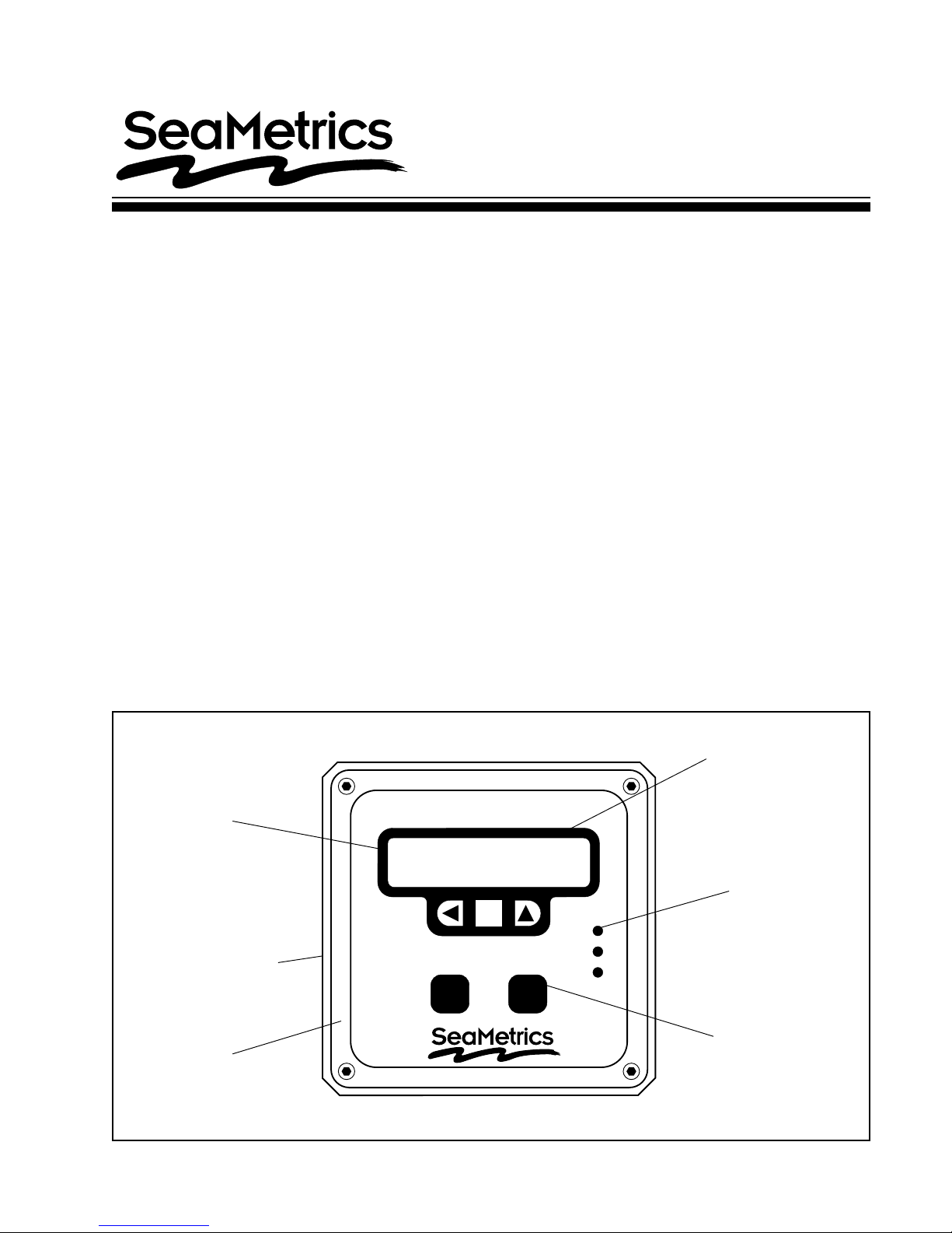
Features
Easy-read
backlit display
Remote control terminals
(inside housing)
Rugged cast aluminum
housing
(wall or panel mount)
ELAPSED
Stop
Set
0:00:00
0 GAL
Resume
Relay 1
Relay 2
Pulse
Output
Choice of
rate/volume units
Alarm output
indicator LED
Accessible
control
buttons
LT-10829-A
Page 1 of 4
Page 2
Installation
Wall Mounting. Using the four screws provided, attach
the two foot brackets to the sides of the enclosure. Then
attach the unit to any secure surface by inserting screws
through the mounting holes in the foot brackets.
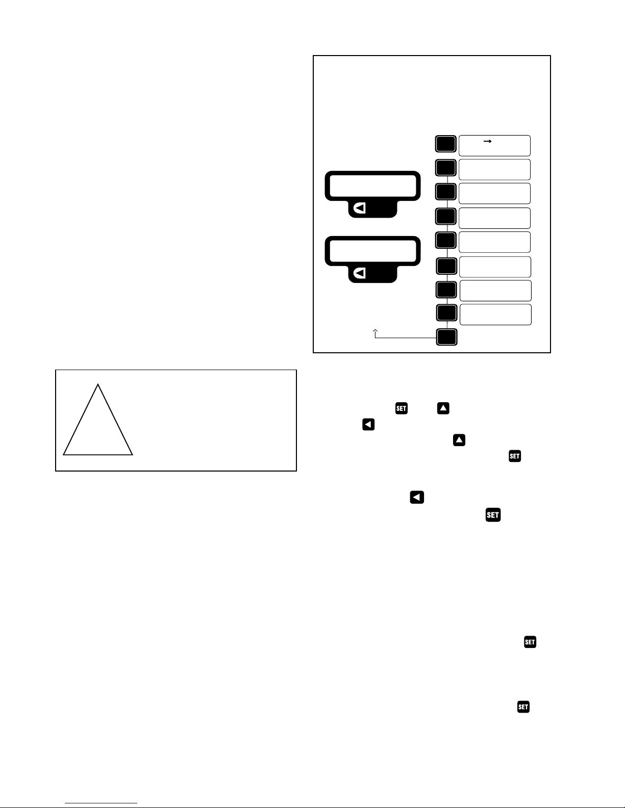
Displays
SETTINGSOPERATION MODE
Panel Mounting. Follow the dimensions given for
“Panel Cutout”. Be sure to include the four corner
screw holes. After cutting and drilling, place the front
plate on the front side of the panel with its gasket
against the panel, and the remainder of the square
housing on the back side. Slide the screws through the
four holes drilled in the panel, and into the threaded
holes in the housing. Tighten until the gasket is firmly
compressed against the panel.
Expose T erminals. Remove the four screws which hold
the front plate to its flange. Remove the front plate. The
display board is attached to this front plate. It is also
connected to the power board by a ribbon cable. For
convenience, this cable can be disconnected while
making connections. Connections can be made inside
the enclosure, or the terminals can be unplugged for
easier access, by gently tugging on them.
Caution: When the
control is powered up, relay
or analog outputs may be
present. If this could be a
hazard, wait to make external
!
connections until programming is complete.
ELAPSED
Flow
Monitor
0 GPM
0 GAL
0:00:00
0 GAL
Flow
SET
Rate
SET
Set Decimal
0.00
SET
SET
SET
SET
SET
SET
SET
1234 GAL
SET
SET
Set K-factor
Set Pulse Out
1.00 Gal
SET 20 mA RATE
123456 GPM
Time Period:
12 HOURS
Alarm Point:
TO CLEAR TOTAL
PRESS UP & LEFT
return to
operation mode
60.00
GAL
MINUTE
Settings
Set Units. Press . Use to select volume
units. Use to select the particular unit desired
(gallons, liters, etc.). Then use to switch to time
units. Again, select the unit desired. Press for
next menu item.
Sensor Connection. Follow the “Connections” diagram
to connect either two or three wires from the flow meter
or flow sensor.
Monitor Alarm Connection. Connect the alarm devices
to the appropriate relay terminals. Note that the relays
have both normally-open (NO) and normally-closed (NC)
contacts.
Analog Connection. This output can be configured 420 mA, 0-10 V or 0-5 V by placing a jumper in the correct position on the analog header. The swith next to
the header selects active (powered) or passive
(unpowered) output. When using the 12 VDC powered
input you may only select passive output.
Power Connection. Connect AC or DC power as
desired to the appropriate terminals. For safety, if using
AC power, be sure to connect the ground terminal
provided to a good earth ground. If using DC power, be
2 of 4
Set Decimal. Use to select zero, one, or two
decimal places on the flow units. Press to advance
to the next menu.
Set K-Factor. The unit will not function properly
until this number is entered. It is simply the number
of pulses which the flow meter or flow sensor puts
out per gallon of liquid. It is marked on the Model/
Serial tag of SeaMetrics flow meters and flow
sensor fittings. On adjustable flow sensors, the Kfactor must be taken from the chart in the flow
sensor instructions, based on pipe size. Press
for next menu item.
Set Pulse Out. An output pulse is activated at the
selected volume intervals if this feature is in use.
Otherwise, it does not need to be set. Press for
next menu item.
Set Time Period. This is the monitoring period at
Page 3

the end of which the unit will alarm if total flow has
exceeded its setting. To set this monitoring period in
hours, use the
underlined is the one being set. Use the
increase it. The
and keys. The digit which is
to
moves one digit to the left. Note
that if the digit to the right is set to “9”, the digit to the
left will only go to “3”. This is because 48 is the
maximum setting allowed. Press
for next menu
item.
Set Alarm Point. This is the maximum total flow
allowed in the time period set above. Use the same
procedure as above to set this value, up to eight
digits. The units are those previously chosen.
Press
for next menu item.
Operation
The last press of the key returns the unit to
operation mode (see “Displays” diagram). In this
mode, pressing either arrow key will toggle back and
forth between two displays, one for flow monitoring
and the other for usage monitoring.
Usage Alarm. Pressing the Start/Stop key will start
the clock and zero the total of the usage monitor. The
clock will increase and the total will accumulate
(provided there is flow) until the end of the monitoring
period. At that time, the usage total and clock will
zero automatically and the cycle will start over. If the
usage total ever reaches its alarm point within the
monitoring time, the usage alarm relays will energize
and remain on until the Resume key is pressed.
Set 20 mA Out. The “SET 20mA RATE” programs
the flow rate at which the output is 20 mA, 5 V or 10
V. Use and to set the maximum flow rate for
full scale output. Press for next menu item.
Clear Total. This function resets the running total
(not alarm point total) back to zero. It does not affect
the alarm point total, which automatically resets
itself at the end of every monitoring time period. To
reset to zero, press and simultaneously.
Connections
(for metering pumps)
AUTODIALER
ALARM
Pulse Outputs
Alternate
12 VDC power
PC1 power supply
P/N 05040
Pulse 1
Pulse 2
Alarm 1
Alarm 2
Main
power fuse
250mA
part # 26926
Customer Supplies
1A Fuse
NC
COM
NO
NC
COM
NO
If the Resume key is pressed during a monitoring
cycle, it will freeze the cycle at its current point.
Pressing it again allows the cycle to resume where it
left off.
Flow Monitoring. The “Rate” indication gives the
current rate of flow. “Total” is a running total of flow
which increases indefinitely unless it is reset (see
Ribbon connector
from display board
RESUME
COM
BATCH
+
s1
–
+
–
5V
10V
A
0m
-2
4
Jumpers
s2
Active
+
A
–
P
Passive
Analog Switch
Analog Jumper
A
B
An Output
RED
WHITE
BLACK
Resume
Start/Stop
Power signal
Sensor Input
Ground
0-10 V or
4-20 mA
Remote
Controls
Dry contact
Meter
Neut
Hot
Gnd
110 VAC
3 of 4
Page 4

Repair
The only field-repairable component on the FT522 is
the fuse. If failure is due to a cause other than a blown
fuse, it is necessary to replace the entire board stack.
Contact your distributor for information.
Panel Cut-out Dimension
!
Caution: Always disconnect
power to the unit before
opening the terminal cover.
Do not reconnect power until
all connections have been
made and the terminal cover
has been replaced.
1/4" holes (4 required)
gasket
5.50"
6.03"
5.50"
PANEL
CUTOUT
6.03"
4 of 4
20419 80th Ave. So., Kent WA. 98032 USA
Phone: 253-872-0284 Fax: 253-872-0285
www.seametrics.com 1-800-975-8153
 Loading...