

Page 1

FT500B
DISCONTINUED
Batch Controller
Instructions
General Information
The FT500 Batch Control is a microprocessor-based
unit which displays rate, batch count, and running total,
and has output functions which can be used for control
or remote monitoring. These include two batch relays
(primary and prewarn) and programmable pulse, for
telemetry and pump pacing.
A large alphanumeric display makes reading easy, and
menu-based programming eliminates the need to
memorize numeric codes. Display units, high/low alarm
settings, pulse output, and meter factor are some of the
programmable features.
The FT500B is housed in a weathertight enclosure with
hinged clear cover. Terminal access is made simple by
a separate terminal compartment cover. Optional meter
input connectors can be ordered for plug-in meter
connection.
Features
Specifications
Power 115 VAC, 12 VDC optional
Temperature 32° - 130° F
Enclosure Non-metallic, NEMA 4X
Outputs Two Form-C SPDT relay
Max. Output Load 3 A at 115 VAC
Sensor Power 12 - 16 VDC, 50 mA
Max. Cycle Size 999,999 units
Max. Output Time 9,999 seconds
Total Display Eight-digit, resettable
Rate Display Five-digit
Sensor Frequency 500 Hz maximum
Simpledisplayeases
descriptive
programming
Hingeddoorcover
forprotection
Sealedexternal
controlbuttons
BatchStatusIndicator
FT500B
FLOWCOMPUTER
Removesfor
easyaccess
Widevariety
ofunits
Simplefour-key
programming
PUB -19096-1000
Page 1 of 4
Page 2

The FT500B is a batch controller designed for use with
DISCONTINUED
SeaMetrics flow meters. Batch size is set using the
alphanumeric display , and relay outputs turn external fluid
controls off or on.
Installation
Mounting. Using three screws, mount the unit to any
secure surface. Drive the center screw first, before lifting
the unit into place. Leave the head extending slightly.
Slide the center mounting lug over this screw head, then
remove the terminal cover to find the other two holes.
Insert screws through these holes and tighten.
Sensor Connection. With the terminal cover removed,
locate the “Sensor” terminals. Following the Connections
diagram, connect flow sensor leads to the appropriate
terminals. Sensor cable can be threaded in through the
strain relief provided with the unit for sealing purposes.
the batch comes within the set number of units of the
end, the high-flow valve will close and the low-flow will
continue open until the end of the batch.
Display Contrast. Change this number only if the unit
is difficult to read, due to light conditions or position on
the wall.
Operation
Displays. When operating, either Batch, Rate, or Total
is always displayed.
Batch: This is the volume of flow since the
START button was pushed to start the batch.
Rate: This is the rate of flow in the selected
units.
Total: This is the running total accumulated
since the beginning of operation, or since the
last reset.
Batch Control Connections. Follow the diagram to
connect to the relay outputs. Note that both Normally
Open and Normally Closed connections are provided.
It is not necessary to use terminals provided for prewarn
output unless a two-stage valving system is being used.
Power Connection. Following the Connections
diagram, connect power. If the unit is standard 1 15 V AC,
be sure to connect a ground wire for safety . The optional
12 VDC unit is supplied with a plug-in power converter.
Observe correct polarity when connecting this unit.
Programming
Program Mode. All programming is done in Program
Mode. The RUN/PROGRAM button turns this mode on
and off.
Units. Select the desired units with the
The FT500B will read and batch in these units.
K-Factor. Select “Meter Change”. The display will read
“K-factor =...” Change this number to read the K-factor
which is correct for your sensor.
Update. It is not necessary to change the display update
time unless the display is excessively jumpy. Update
time can be increased to a maximum of 2,000
milliseconds (2 seconds).
Batch Size. Select Batch Change. The first setting is
the basic batch size. Use the
the desired size. The second setting is the prewarn
amount. This only needs to be set if a two-stage system
is being used. It represents the number of units before
the end of the batch at which the K1 relay will drop out.
In the typical application, the high-flow valve is connected
to K1, and the low-flow valve is connected to K2. When
▲
▲ / buttons to set this to
▲
▲ and keys.
Batch Operation. Pushing the START button causes
the output relay(s) to energize. The relays remain
energized until the end of the batch unless the STOP
button is pushed. The RESUME button can be used to
return to operation after a mid-batch stop.
The Prewarn relay energizes at the same time as the
Batch relay, so that if dual valves are being used (high
flow and low flow) they will open at the same time.
However, at the set number of units before batch end
(“Prewarn” setting) the Prewarn relay will drop out. In
this way the flow can be lowered at the end of the batch
for greater precision.
Maintenance and Repair
Front Panel Removal. The front panel must be removed
to gain access to fuses, or to replace a printed circuit
board. Open the clear cover. Remove the two screws
on the left side and the two hex standoffs on the right.
Gently loosen the panel and lift it out. The display board
is attached, and will come with the panel. This exposes
the fuses which are on the power supply board.
Fuses. The power supply and the pulse output circuit
have fuse protection. The two fuses are on the power
supply board. Replace a blown fuse with a .5 amp.
Backup Battery. Programmed settings and total flow
are stored in battery-backed memory to protect them
from power failure. The life of the battery is approximately
ten years. It is recommended that the battery be changed
well before the end of its expected life. To change the
battery, first remove the front panel. The coin-shaped
battery is in a holder on the under side of the display
board. Remove and replace it with a BR2325 or
equivalent.
2 of 4
Page 3
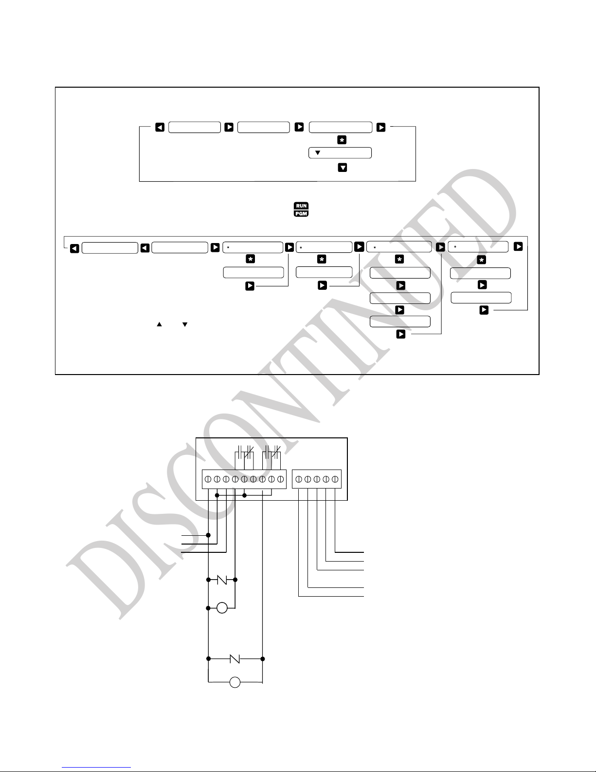
Displays
DISCONTINUED
Dsply Contrast = 14
UNITS = GALLONS/MIN
When in the PROGRAM MODE the
Note:
" " and " "keys add or subtract
from the value displayed
RATE 1234 GPMBatch 25 Gals
for METER change
K Factor 1.000
TOTAL 12345678 GAL
RUN MODE
PROGRAM MODE
for UPDATE change
UPDATE TIME=1000ms
TO RESET TOTAL
AND UPDATES UNITS
RESETS TOTAL
for BATCH change
123456 Gals / BATCH
1234 Gals Prewarn
1234 Gals / Pulse
Note:
The 4-20ma menu only appears if
the optional AC10 board is installed.
for 4-20ma change
4Ma = 97 GPM
20Ma = 195 GPM
Connections
110 VAC
Input
Neutral
Hot
{
Ground
High Flow
Low Flow
Valve
Valve
Neutral
Hot
GND
GND
+12
Out
Input
GND
12 VDC - (Black)
Input Signal (White)
12 VDC + (Red)
- (Black)
+ (Red)
Scaled Output Pulse
}
to Metering Pump
MOV Transient Surge Suppressor
{
To Meter
3 of 4
Page 4

4 of 4
DISCONTINUED
20419 80th Ave. So., Kent WA. 98032 USA
Phone: 253-872-0284 Fax: 253-872-0285
www.seametrics.com 1-800-975-8153
 Loading...