

Page 1
FT415 Flow Computer
ARCHIVED
Instructions
SpecificationsGeneral Information
The FT415 is a microcontroller-based rate/total indicator powered by a lithium battery. It displays rate and
total, and provides a programmable pulse output for use
in metering pump pacing or datalogging.
The rugged cast-aluminum housing is gasketed for maximum environmental protection, and the electronics are
potted into a solid block of urethane. A membrane keypad allows settings to be changed without removing the
cover. The wall mount version comes with brackets for
wall mounting, and a kit (MK10) is available for field installation on TX80-series flow sensors. The FT415 can
also be factory or field installed on a TX100/200 series
sensor or WT meter. (Micropower sensors are required
to prolong battery life.)
The standard output is a programmable 0.1 second opencollector transistor (TTL) pulse which can be used to
trigger most externally-paced metering pumps.
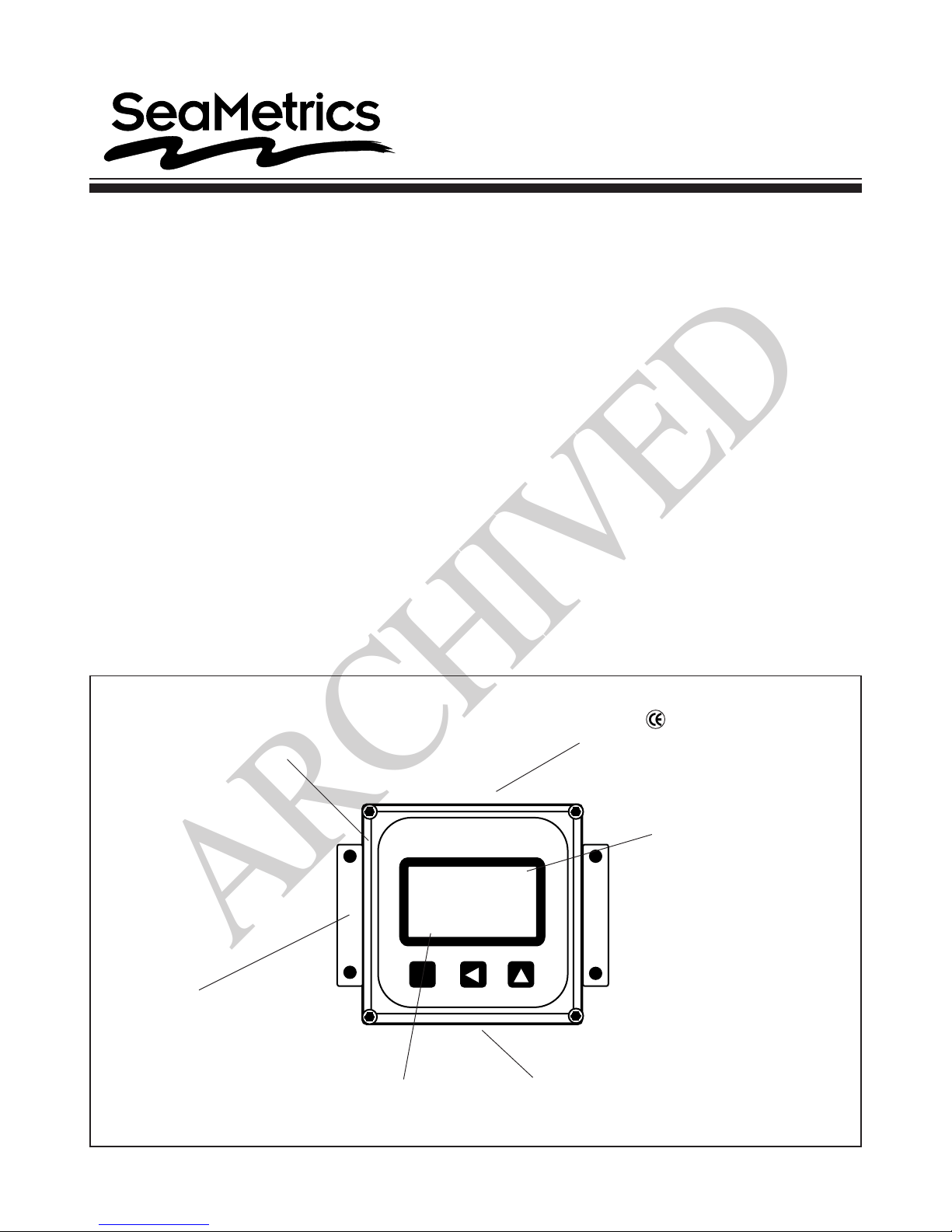
Features
Sturdy gasketed cover
with electronics
potted in
Display
Rate 6-digit autorange, 1/2"
character height
Total 8-digit, 5/16" character
height
Pulse Output 0.1 second open collector
pulse
Input Micro-power GMR sensor
(square wave)
Input Range Minimum: 20 mV peak-peak
Maximum: 6V peak-peak
K factor Range 0.050 - 999999.9
Pulse Output Range 0.1 - 200,000 units/pulse
Battery Type Lithium "C", 3V, replaceable
Normal Battery Life 3-5 years
Temperature 0 C - 70 C
Environmental NEMA 4X
Tested for Immunity
and Emissions standards
Removeable foot brackets
for wall mounting
2341678.9
SET K RESET
SET
Easy set-up
prompts
Large rate numerals
10.5
Triple bosses for
watertight input/output
connections
LT-10621-B
Page 1 of 4
Page 2

Installation
!
ARCHIVED
To mount the FT415W on a wall, hold the unit in the
desired position, mark the holes in the mounting feet,
drill, and mount with screws.
This unit can also be mounted directly on a flow sensor
for local reading. Note that the FT415 requires the
optional micropower sensor, in order to conserve battery life. For loop or other external power, the FT420 is
recommended, and can be installed on any standard
sensor.
If the unit was ordered as an FT415M, factory mounted
to the top of a 100 or 200 Series flow sensor, no further
installation is required.
To mount the unit on a flow sensor, an MK10 mounting
kit is required. Then remove the housing cover. Place
the lower half of the housing in the groove on the top of
the flow sensor. An adapter from the kit is included in
the lower housing, which threads into the top of any 80Series flow sensor. Pull the sensor wires through the
hole in the center of this adapter, then thread the adapter
into place. Tighten the adapter using a screwdriver. (See
diagram). Connect the wires, then replace the housing
cover, orienting it any direction as desired for viewing
convenience.
Connection
To connect to the FT415 to a flow sensor, follow the
diagram marked “Connections”. This diagram also
shows the connections for an external device, such as
a chemical metering pump.
Programming
Caution: If pulse output is being
used to control an external device,
such as a metering pump, do not
connect the pulsed device until pro-
gramming is completed. If malfunction or incorrect programming of the pulse output
could cause personal injury or property damage,
separate safeguards must be installed to prevent
such injury or damage.
At a minimum, every FT415 must be programmed with
the “K-factor”. This is simply the number of pulses per
gallon which the meter or flow sensor produces. (If you
wish the FT415 to read in another unit, enter the number of pulses per that unit. For example, if the desired
units are liters, the K-factor is the number of pulses per
liter that the flow sensor produces.)
To find the K-factor on any SeaMetrics flow sensor fitting or in-line meter, look on the model-serial label. The
line reading K = xxxx is the desired number. For adjustable sensors (101,201,115,215) look in the instruction
manual under your pipe size.
Set K. Begin by pressing the key SET once. The prompt
SET K should appear on the display. The digit to the far
right will be blinking. Use the up arrow key to reach
your desired digit. Then press the left arrow key to move
to the next digit. Repeat the process until the entire number is entered. (Note that the decimal is fixed at three
places. If you only have two decimal places for your Kfactor, enter a zero for the third digit.)
Chemical
FT415
on TX81
Flow
2 of 4
Control Pulses
Proportional
Chemical
Set P. If the pulse output is to be used, set the desired
pulse rate. Note: If the pulse output feature is not
being used, this step can be skipped. The P (pulse
output) setting does not affect anything if it is not
being used. This is the number of gallons (or other
units, if you are using them) between pulses. The second time the SET key is pressed, SET P will appear.
Follow the same process as above to enter the desired
number.
Pressing all three buttons at once will put the unit into
low alarm. Pressing all three again will put the unit into
high alarm.
Press the ARROW LEFT
keys to set the flow rate at which you want to have the
output pulse switch on.
and ARROW UP
Page 3

Sensor Mount: Step 1
ARCHIVED
Sensor Wires
Sensor Mount: Step 2
Sensor Wires
Standard Connections
Red
White
Black
Micropower Sensor Only
Battery Type:
Lithium "C, 3V, replaceable
+
Sensor
Input
s
-
- +
Outputs
- +
Sensor Pulse
To Other
Control
Pulse Responsive
Metering Pump
3 of 4
Page 4

Set Decimal Point. The third time the SET key is
ARCHIVED
pressed, a D prompt appears. Pressing the up arrow
key switches back and forth between no decimal place
and one decimal place.
Set Time Unit. The fourth time the SET key is pressed,
a blinking arrow appears. Press the up arrow key to
select S (seconds), M (minutes), H (hours) or D (days).
Operation
To return to normal operation after entering settings,
press SET for a fourth time. The rate and total indicator
numbers should appear in the display. If the unit is connected to an operating flow sensor, the larger-sized
digits indicate flow rate and the smaller-sized digits indicate total.
Unless the unit has been ordered with the non-reset
option, a RESET prompt is constantly visible in the lower
right corner, above the up arrow key. Press this key at
any time to reset the totalizer to zero.
Battery Change
The expected average life of the battery is approximately
four years, with a range of 3-5 depending on the frequency of the input. Pull the battery from its holder and
replace it with the new one. Note that when the battery
is removed, all of the settings previously entered will
be retained. However, the totalizer will reset to a previous total, which represents the last auto-backup (approximately one hour intervals.) If it is necessary to save
the exact current total at the time of the battery change,
save before removing the battery, by simultaneously
pressing the SET and up arrow keys. Then press SET
again, then again simultaneously press the SET and
up arrow keys.
Dimensions
2341678.9
SET
3.93"
4.52"
10.5
with Wall Mount Brackets
FT415
3.93"
2.06"
FT415
Sensor-Mount
2.57"
2.78"
4 of 4
20419 80th Ave. So., Kent WA. 98032 USA
Phone: 253-872-0284 Fax: 253-872-0285
www.seametrics.com 1-800-975-8153
 Loading...