

Page 1

FT410 Flow Computer
DISCONTINUED
Instructions
SpecificationsGeneral Information
The SeaMetrics FT410 is a compact digital flow monitor
with user-programmed output features. Combined with
an IP Series insertion flow sensor or a WT turbine meter,
it is ideal for flow rate and total indication, chart recording, and proportional chemical feed. It is available in wall
or panel-mount enclosures, or in a round cast-aluminum
housing mounted directly on a SeaMetrics meter. For
wall-mounting, the non-metallic enclosure is splashproof
and has a clear cover. The housing for panel mounting
is standard 1/4 DIN-sized, with gasketed front panel and
membrane switches. Wall and meter-mounted enclosures are NEMA 4X; Panel-mounted enclosures are
NEMA 12.
An eight-digit totalizer is resettable, unless ordered with
non-reset option. Programming prompts simplify set up
by indicating the next step. Pulse output is a programmable 0.1 second open-collector transistor pulse (an
optional dry contact pulse output is available) which is
compatible with electronic metering pumps, PLC's, computer input cards, and SeaMetrics controls. An optional
4-20 mA output feature is front-panel programmable in
standard flow rate units.
Power 11-28 VDC
Flow Sensor Power 5 Volts DC, 50 mA maximum
Temperature 0° C to 70° C
Display Custom 8-digit LCD,
0.4" digits
Totalizer 8-digit resettable
(non-reset optional)
Rate Indication 8-digit
K Factor Range .050 - 2000.000
Pulse Output Range 0.1 - 200000.0 gallons per
pulse
Pulse Output 0.1-second open-collector
transistor, 100 mA, 40 VDC
maximum; optional FORM C
SPST relay contact closure
5A@ 24VDC
Analog Output
(Optional) 4-20 mA isolated 24 VDC, 500
Ohm maximum; may be wired
non-isolated
Analog Output
Resolution 500 counts full scale
Sensor Output 100 mA, 40 VDC maximum
Features
Promptsappear
whenprogram
buttonispushed.
"SETP"means
setpulseoutput
ingallonsper
pulse.
Otherprompts:
•SETK(meterfactor)
•SET20mA(optional)
•SETDP(totalizer)
ResetTotalizertoZero
(Non-resettableoptional)
FT410
RESET RATE/TOTAL
SETP
410.0
PROGRAM
-
+
Presstochange
settings:
•K-factor
•PulseOutput
•4-20mA(optional)
SwitchesbetweenRateand
TotalDisplays(Alsorespondsto
magnetoutsideenclosure)
Selectable
decimal
point
Buttonsincrease
ordecreasesetting
PUB -19740-1000
Page 1 0f 4
Page 2
Installation
!
DISCONTINUED
FT410W: Wall Mounting. Four 3/16" screw holes are
located at the bottom of the front cover screw holes.
Mark the locations through the holes, then drill. Slip
screws down the holes and tighten.
FT410P: Panel Mounting. Use the dimensions on the
back page for making the panel cutout. Locate the dovetail mounting bracket grooves on the side and the top of
the unit. After cutting out the panel, break any sharp or
rough edges, then slip the panel gasket in place behind
the FT410 bezel and slide the unit through the panel
hole. Install the mounting brackets in their dovetail
grooves, with the slots of the clamping screws facing
out. Tighten the screws to pull the unit tightly against the
panel and compress the gasket slightly.
Connections
FT410M: This unit is pre-wired with 18 ft. of four-con-
ductor cable. See diagram for color coding of the leads.
If desired, the cable supplied can be removed, and connections can be made inside the unit, following the Connections diagram.
FT410M - Standard Unit:
Red (+) 12 VDC to power supply
Black (-) 12 VDC to power supply
Green (+) pulse output
White (-) pulse output
Sensor Out terminals are provided for passing on the
signal from a flow sensor to a second electronic device.
They do no need to be connected unless using such a
device.
FT410P: This unit is ordinarily supplied without pre-wiring. T o reach the terminals, remove the four screws which
hold the back cover of the housing in place. Follow the
connections diagram
Analog Output Board. The optional 4-20 mA output
uses a third printed circuit board which plugs into the
terminal connection board. This board is pre-wired at
the factory with a jumper, so that powering the FT410
automatically provides power to the current loop. If an
isolated 4-20 mA output is required (see Connections) it
is necessary to remove the jumper and rewire as shown
in “Analog Output - Isolated”.
Programming
Caution: If pulse output is being
used to control an external device,
such as a metering pump, do not
connect the pulsed device until
programming is completed. If malfunction or incorrect programming of the pulse output could
cause personal injury or property damage, separate safeguards must be installed to prevent such
injury or damage.
FT410W - Standard Unit:
Red (+) 12 VDC to power supply
Black (-) 12 VDC to power supply
FT410M, FT410W - With Analog Option:
Red (+) 12 VDC to power supply
Black (-) 12 VDC to power supply
Blue (+) 4-20 mA
Orange (-) 4-20 mA
FT410W: This unit is pre-wired with 6 ft. of two-conductor cable for the power connections. See diagram for
color coding of the leads. T o complete the wiring needed
for the application, remove the front clear cover, then
remove the front panel to reach the terminals. Turn the
front panel over, with the circuit boards still attached.
Follow the connections diagram.
Note the polarity of the Pulse Output terminals. Be sure
to observe proper polarity when connecting to an electronic metering pump. If the pump does not respond to
the pulse output, try switching polarity.
Set K-Factor. To begin programming, press the PROGRAM key . The prompt SET K should appear . The Kfactor is the number of pulses per volume unit. This
number is provided with SeaMetrics meters, in pulses
per gallon. If the FT410 is to read in other units, the number provided with the meter must be converted. The
FT410 will then totalize in the selected units, and the
rate reading will be in those units per minute. The rate is
always in units per minute.
To enter the K-factor, press the “+” or “-” keys until the
desired number is reached.
Set Pulse Output. Pressing PROGRAM a second time
brings up the prompt SET P. This setting controls the
pulse output, if it is being used. It is set in units per pulse.
For example, if the FT410 is reading in gallons, a setting
of 2.00 means that a pulse will occur every 2 gallons.
Settings may be as small as 0.1, which means that there
is a pulse every 0.1 units. If the optional dry contact pulse
output is present, SET P sets that pulse output also.
(NOTE:
Pulse output is limited to 100 ppm
)
2 of 4
Page 3

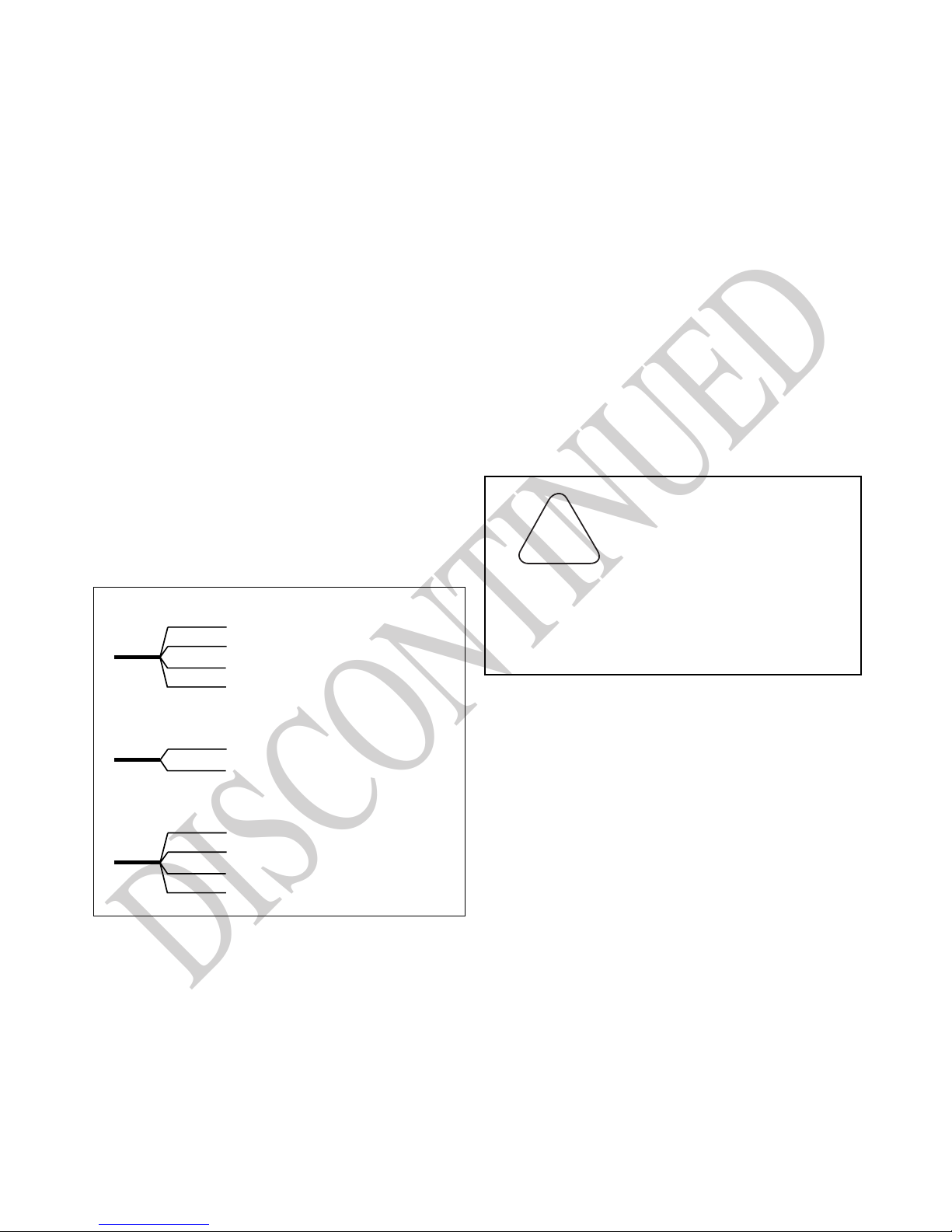
Standard Connections
DISCONTINUED
To 2nd FT410
or control
DC Power
RED
BLACK
RED
WHITE
BLACK
IP SENSOR
Analog output - Non-Isolated
DC Power
RED
BLACK
RED
WHITE
BLACK
IP SENSOR
+
+
SIG
-
+
+
SIG
-
POWER
INPUT
SENSOR
+
POWER
SENSOR
-
INPUT
OUT
SENSOR
OUT
PULSE
+
-
+
-
NC
COMNO
OUT
SENSOR
OUT
PULSE
GREEN
WHITE
DRY CONTACT
PULSE OUTPUT
(OPTIONAL)
+
+
-
NC
DRY CONTACT
COMNO
PULSE OUTPUT
(OPTIONAL)
METERING PUMP
To 2nd FT410
or control
METERING PUMP
GREEN
WHITE
Analog output - Isolated
DC Power
IP SENSOR
Blue +
OPTIONAL 4-20mA
CURRENT LOOP
Orange -
CHART RECORDER
To 2nd FT410
or control
METERING PUMP
+
-
POWER
+
SIG
-
-
24
VDC
++-
INPUT
SENSOR
+
OUT
-
SENSOR
+
-
OUT
PULSE
NC
COMNO
DRY CONTACT
PULSE OUTPUT
(OPTIONAL)
OPTIONAL 4-20mA
CURRENT LOOP
CHART RECORDER
3 of 4
Page 4

Set 4-20 mA Span. If the optional 4-20 mA board is in-
DISCONTINUED
stalled, the prompt SET 20 mA will appear. Set this value
to the flow rate, in units per minute, at which the full 20
mA output is desired. Zero flow will automatically be
scaled to 4 mA.
Set Decimal Point. Pressing PROGRAM again brings
up SET DP. Choices are one decimal place or none.
Pressing the +/- keys alternates between the two. Typically, a decimal place is only required with low-flow
meters. Exit programming mode. Pressing rate/totalizer
button returns unit to operating state.
Repair
The only field-repairable component on the FT410 is
the fuse. The fuseholder is found on the back of the circuit board stack. Replace with a Littlefuse 3AG 1/2-Amp
or equivalent automotive-type fuse.
On units with the 4-20 mA option, it is necessary to remove the analog board at the back of the stack to reach
the fuse. Unplug the board by gently tugging on it. On
some models, it is also necessary to remove four screws
to get the analog board loose.
Operation
In normal operation the FT410 displays rate or total.
Pressing RA TE/TOTAL alternates from one to the other .
This can also be accomplished from outside the unit by
touching a magnet to the outside of the case in the general vicinity of the RA TE/TOT AL key. When rate is showing, total continues to accumulate. Unless the unit has
the NR (non-reset) option, pressing the RESET key sets
total to zero. T otal is stored in nonvolatile memory and is
kept on loss of power, although the unit will not operate
during the power outage.
Mounting Dimensions
FT410W Wall Mount
If failure is due to a cause other than a blown fuse, it is
necessary to replace the entire board stack. Contact your
distributor for information.
FT410P Panel Mount
3/16" MOUNTING HOLES
UNDER COVER SCREWS
3"
4 of 4
4.20"
RESET RATE/TOTAL
+
PROGRAM
FT410
5"
-
5"
20419 80th Ave. So., Kent WA. 98032 USA
Phone: 253-872-0284 Fax: 253-872-0285
www.seametrics.com 1-800-975-8153
3.75"
3.75"
FT410
RESET RATE/TOTAL
+
PROGRAM
3.55"
3.5"
-
2"
3.55"
PANEL CUTOUT
 Loading...