

Page 1
d
C
I
FT430/440/450
Rate/Total Indicator
Instructions
Optional Protective Cover Closed
o
m
e
i
p
f
PROUDLY
MADE
Precision Flow Measurement
An ON
CON Brand
IN THE
USA
i
t
r
e
C
ISO
9001:2008
a
n
y
Page 2

Page 3

TABLE OF CONTENTS
General Information
General Information ...................................................................................................................................................Page 3
Specications ................................................................................................................................................................Page 3
Features ...........................................................................................................................................................................Page 4
Pulse Output Functions .............................................................................................................................................Page 4
Installation
Wall Mount .....................................................................................................................................................................Page 5
Meter Mount .................................................................................................................................................................Page 5
Panel Mount ..................................................................................................................................................................Page 5
Connection Diagrams
FT450 Standard .............................................................................................................................................................Page 6
FT430/3-Wire Mechanical Meter ...........................................................................................................................Page 6
Connections for FT430-139 or FT440-139 —115Vac Option ......................................................................Page 7
FT440/3-wire Mechanical/Dual Scaled Pulse Output ....................................................................................Page 7
FT440/EX Magmeter ...................................................................................................................................................Page 8
FT440-139/EX Magmeter .........................................................................................................................................Page 8
Settings
K-Factor ...........................................................................................................................................................................Page 9
Changing Flow Indicator Settings .........................................................................................................................Page 9
Menu Navigation .........................................................................................................................................................Page 9
FT440 Secondary Menu Functions ........................................................................................................................Page 11
FT430/440/450 INSTRUCTIONS
Troubleshooting
Problems .........................................................................................................................................................................Back
Probable Causes ...........................................................................................................................................................Back
Things to Try ..................................................................................................................................................................Back
Seametrics • 253.872.0284 Page 3 seametrics.com
Page 4
GENERAL INFORMATION
FT430/440/450 INSTRUCTIONS
The FT430/440/450 ow computers are microcontroller-
based indicator/transmitters that interface with pulse
output ow sensors to compute and display ow rate, ow
total, and also generate output signals representing ow.
The FT430 and FT450 have one scaled pulse output and
one pulse pass through. The FT440 has two scaled pulse
outputs. Galvanic isolation is provided for most pulse
outputs.
The FT450 is battery powered while the FT430 may be
powered by an external DC power source or an optional
internal AC power supply*. The FT440 is a “two-wire” or
“loop powered” device, meaning that it is powered by the
4-20 mA loop circuit itself. An optional internal AC power
supply* is available for the FT440 with dual 24 and 12VDC
outputs to power both the loop and sensors requiring
more power than the loop can supply.
Features
Pulse and 4-20mA analog outputs can be used to signal
external devices, e.g. certain metering pumps and water
treatment controls. Alternatively, one or more pulse
outputs can be congured as alarm outputs. These ow
computers can be password protected to prevent resetting
the total or changing conguration settings.
The FT430/440/450 meters are available in wall and meter
mount congurations. The FT430 and FT440 models
can also be panel mounted. Some congurations can
be converted from wall to meter or meter to wall after
installation if needed. Consult factory for details.
Order the FT440 only if a 4-20mA output signal is a
requirement and the FT450 if internal battery power is
needed. Otherwise the FT430 oers the most exibility.
*Internal power supply is available for the wall mount option only.
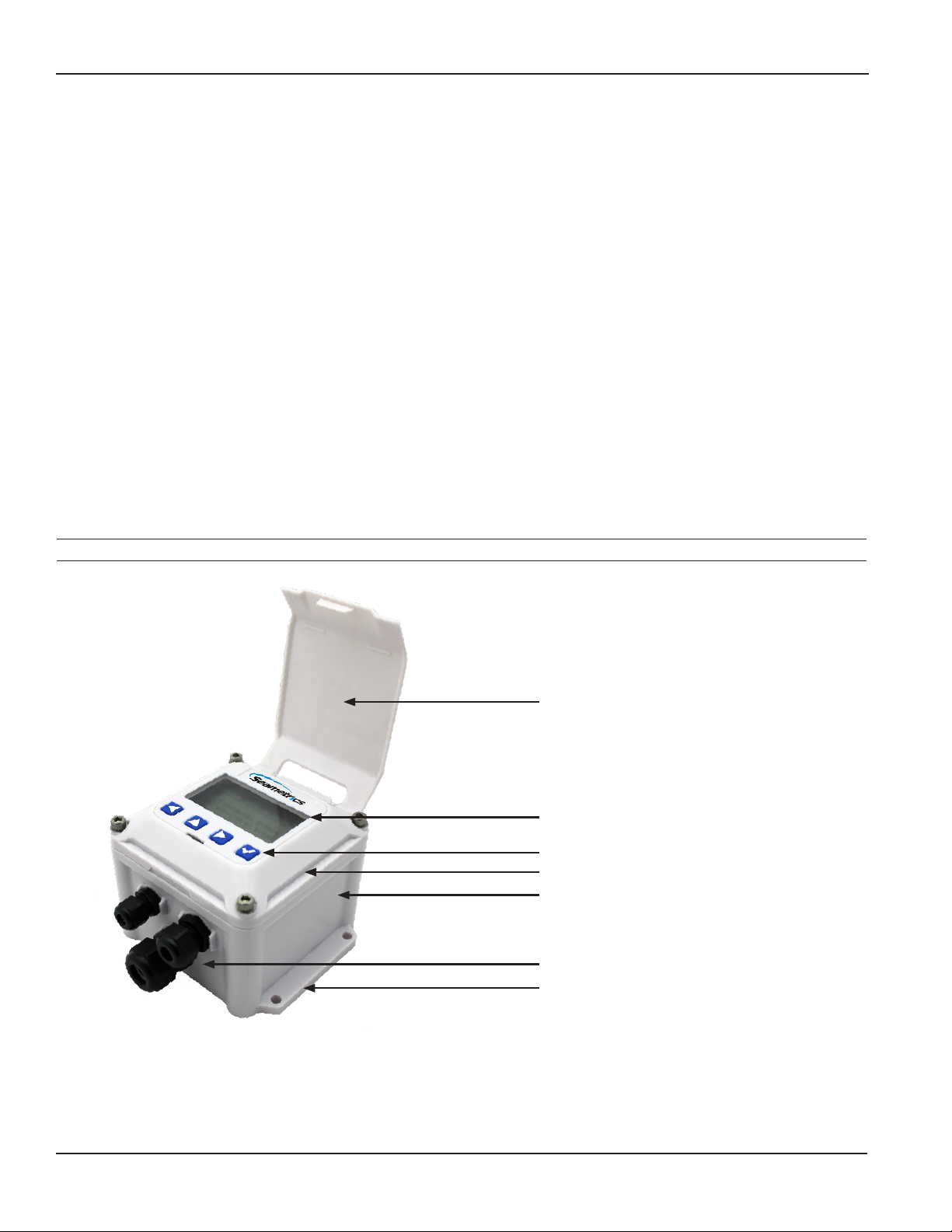
Protective Cover (Optional)
Display
Setup Keys*
Electronics Module
Lower Housing
Cable Gland Strain Relief
Wall-Mount Brackets
* Includes password protection for tamper
prevention when needed
Seametrics • 253.872.0284 Page 4 seametrics.com
Page 5
GENERAL INFORMATION
FT430/440/450 INSTRUCTIONS
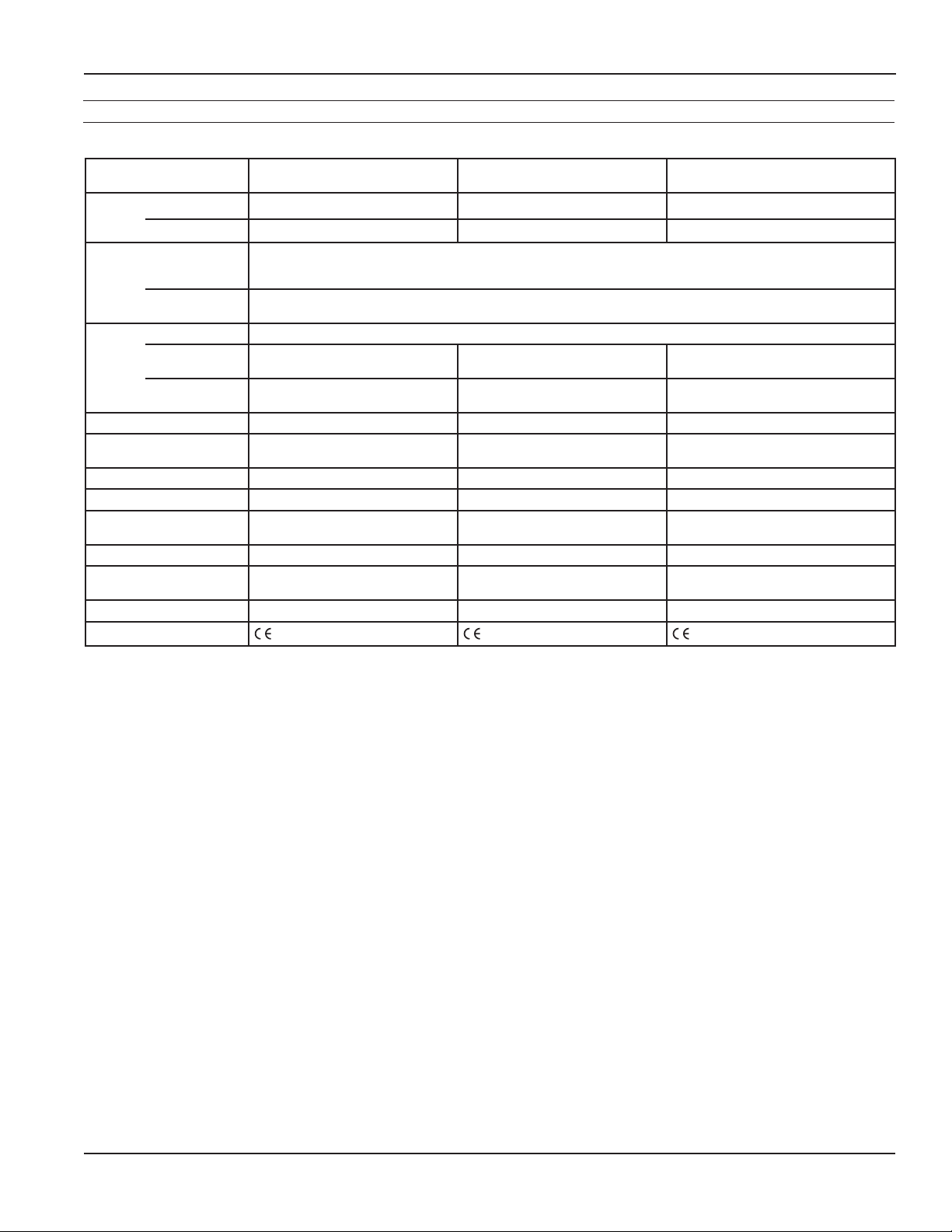
Specications*
FT440 FT450FT430
Power
Display
Rate 5-digit autorange 5-digit autorange 5-digit autorange
7-30Vdc, 4mA
Total 8-digit 8-digit 8-digit
Gallons/Second/Minute/Hour/Day, Liter/Second/Minute/Hour/Day, Cubic Feet/Second/Minute/Hour/Day, Cubic
Units Rate Units
Meters/Second/Minute/Hour/Day, Mega Liters/Day, Million Gallons/Day, Fluid Oz/Second/Minute/Hour/Day, Barrels/
Second/Minute/Hour/Day
Total Units
Gallon, Gallon x 1000, Liters, Mega Liter, Cubic Meter, Acre Feet, Cubic Feet,
Cubic Feet x 1000, Million Gallon, Acre Inch, Fluid Ounce, Barrels
Outputs Pulse Output 1 Scaled pulse output, high alarm output or low alarm output. Optoisolated on FT430 and FT440.
Pulse Output 2 Pulse pass through
Loop Power
Output
N/A 4-20mA Loop N/A
Set P Range 0.1 - 99999.9 units/pulse 0.1 - 99999.9 units/pulse 0.1 - 99999.9 units/pulse
Input 5V pulse or contact closure 5V pulse or contact closure
Input Range 0.75
2
- 2000Hz 0.752 - 2000Hz 0.752 - 550Hz
K-Factor Range .001 - 999999.999 .001 - 999999.999 .001 - 999999.999
Flow Alarm Output
Range
0.1 - 99999.9 0.1 - 99999.9 0.1 - 99999.9
Operating Temperature -5˚ to 55˚ C (23˚ to 131˚ F) -5˚ to 55˚ C (23˚ to 131˚ F) -5˚ to 55˚ C (23˚ to 131˚ F)
Non-Operating
Temperature
-40˚ to 75˚ C (-40˚ to 158˚ F) -40˚ to 75˚ C (-40˚ to 158˚ F) -40˚ to 75˚ C (-40˚ to 158˚ F)
Environmental NEMA 4X, IP67 NEMA 4X, IP67 NEMA 4X, IP67
Regulatory
Mark Mark Mark
9-30Vdc, 4mA (4-20 mA when
loop-powered)
Scaled pulse output, high alarm
output or low alarm output.
1
Lithium “C”, 3.6Vdc, replaceable. Life is
~5 years depending on usage.
1
Pulse pass through
Micropower GMR Sensor
(square wave)
* Specications subject to change • Please consult our website for current data (www.seametrics.com).
1 Scaled output pulses have a xed width of 100ms. Maximum pulses per second is 6.5Hz
2 For pulse frequencies <1 Hz, increase setting in SET F menu to 3 or higher.
Seametrics • 253.872.0284 Page 5 seametrics.com
Page 6

GENERAL INFORMATION
3.374
4.77 (121.2)
(110)
#10
.10"
.50"
FT430/440/450 INSTRUCTIONS
Pulse Output Function Table
PULSE OUTPUT 1 (SCALED) FT430 FT440 FT450
TYPE Current sinking Current sinking Current sinking
MAX. VOLTAGE 36 Vdc 36 Vdc 36 Vdc
MAX. CURRENT 100 mA 100 mA 100 mA
MAX. FREQUENCY 6.5 Hz 6.5 Hz 6.5 Hz
PULSE WIDTH 100 ms 100 ms 100 ms
ISOLATION 300 V 300 V
CONFIGURABLE AS ALARM YES (High or Low) YES (High or Low) YES (High or Low)
PULSE OUTPUT 2 (SCALED) FT430 FT440 (Note 2) FT450
TYPE
MAX. VOLTAGE 36 Vdc
MAX. CURRENT 100 mA
MAX. FREQUENCY 6.5 Hz
Not Available
PULSE WIDTH 100 ms
ISOLATION 300 V
CONFIGURABLE AS ALARM YES (High or Low)
PULSE OUTPUT 2 (PASS-
FT430 FT440 FT450
Current sinking
THROUGH)
TYPE Current sinking
MAX. VOLTAGE 36 Vdc 36 Vdc
MAX. CURRENT 10 mA 100 mA
MAX. FREQUENCY
PULSE WIDTH SAME AS SENSOR INPUT SAME AS SENSOR INPUT
ISOLATION 300 V
CONFIGURABLE AS ALARM NO NO
2000 Hz
NOTE 2
Not Available
NOTE 1
Not Available
Current sinking
550 Hz
NOTE 1
NOTE 1: 150 V eective isolation when using Seametrics micropower sensors. • NOTE 2: With 2000 ohm or lower pull-up resistance.
Screw
4.10 (104.1)
4.35 (110.5)
(63.5)
4.33
4.10
2.50
(104.1)
#10
Screw
3.37
(85.6)
Dimensions are in Inches (Millimeters)
0.78
.78"
(19.8)
0.10 (2.5)
0.50
(12.7)
Seametrics • 253.872.0284 Page 6 seametrics.com
Page 7

INSTALLATION
FT430/440/450 INSTRUCTIONS
Wall Mount. To mount an FT430/440/450 indicator to
the wall, hold the unit in the desired position, mark the
holes in the mounting feet, drill and mount with screws.
A meter-mounted indicator can be converted to a wall
mount using an adapter mounting kit. Contact distributor
for information.
Wall mount housings for FT units are supplied with 3 cord
grips of dierent sizes. Be sure to use the appropriate sized
cord grip for your cable or cables and to assure any unused
cord grips are well sealed with a properly sized plug (these
plugs will come in the cord grips that are supplied with the
wall mount housing when shipped from the factory.) There
will be a properly sized cord grip for any cable supplied by
Seametrics.
Meter Mount. If the FT430/440/450 indicator was ordered
as a meter mount model, the housing is already mounted
directly to the ow sensor and needs no further installation.
An FT430/440 module can be converted from a wall-mount
to an IP meter-mount unit using the mounting kit (contact
distributor) that includes a lower housing and associated
hardware and installs as follows:
1. Remove the strain relief through which the ow
sensor cable runs.
2. Cut the cable to about 6” in length. Carefully strip
the cable jacket to expose the three colored wires
(red, white, and black) inside.
3. Route the wires through the threaded connector
pre-installed in the bottom of the housing.
4. Start the threaded connector into the female thread
on the top of the ow sensor. Be sure to match the
oblong shape on the bottom of the housing to the
depression on the top of the ow sensor.
5. Using an ordinary screwdriver inserted in one side
of the slot (see drawing), tighten the screw as much
as possible.
6. Strip the wire ends, make the connections to the
indicator as shown in Connections Diagrams, and
then use the cover screws to attach the indicator to
the top of the housing.
Meter Mount
Sensor Wires
Sensor Wires
Seametrics • 253.872.0284 Page 7 seametrics.com
Page 8

INSTALLATION
FT430/440/450 INSTRUCTIONS
3.56 (90.4)
Panel Cutout
2.4 (61) TYP
3.5 (88.9) TYP
(PANEL CUTOUT)
3.56
(90.4)
.218 (5.5)
Every threaded opening in any meter housing will either
be lled with a plug or a cord grip when the unit leaves
the factory. If a plug is removed to allow for a cable to
be installed, be certain a cord grip with cable gland is
installed in its place and that the thread is sealed with a
thread sealant or proper O-ring. Bare plastic threads in a
metal housing are not sucient and will cause atmospheric
moisture to be sucked into the housing due to varying
atmospheric pressure.
Cord Grips. Cord grips supplied by Seametrics are
properly sized for the openings and threads in our meters
and housings and are properly sized for cables oered
by Seametrics. Cord grips must be well sealed into their
housings and must be well sealed onto any cable that is
installed through that cord grip. The compression nut
for every cord grip must be left installed on the cord grip
and must be snugly tightened on the cable or on a plug
that would take the place of the cable. Plugs with anges
are to be installed from the outside of the compression
nut to assure that the tapered features inside the nut can
properly compress the cable gland when tightened
Panel Mount. Using the “Panel Cutout” drawing as a guide,
cut a hole in the panel. Place the FT430/440 indicator on
the panel and mark the holes, drill, and mount with the
supplied screws and washers.
Connections. To connect the ow computer to a ow
sensor or an external device such as a chemical metering
pump, follow the Standard Connections diagrams on the
following pages.
Environmental protection. Anytime an FT unit, or other
meter is opened or otherwise exposed to the surrounding
environment it is the responsibility of the installer to assure
the housing is left clean, dry, fully sealed and otherwise
protected from the surroundings. Moisture and dirt will
damage electronics and care must be taken to keep the
electronics housings clean and dry.
When installing, or re-installing any FT, or other housing
cover to any enclosure be certain the gasket is in good
condition, is clean and has not been damaged in any way.
Then be certain to snugly torque the fastener(s) so the
gasket is well sealed.
Wall Mount Housings. Wall mount housings for FT units
are supplied with 3 cord grips of dierent sizes. Be sure
to use the appropriate sized cord grip for your cable or
cables and to assure any unused cord grips are well sealed
with a properly sized plug (these plugs will come in the
cord grips that are supplied with the wall mount housing
when shipped from the factory.) There will be a properly
sized cord grip for any cable supplied by Seametrics.
Cables. We recommend the use of cables that are supplied
by Seametrics. If other cables are used the outside of the
cable must be round and smooth so the cord grip can
properly seal the cable.
Keep in mind that most cables are not sealed on the inside
and a cable that is well sealed to a housing but left open on
the weather end is just a conduit for moisture and changes
in atmospheric pressure will cause, over time, moisture to
be drawn into the housing through any exposed cable
end, causing failure of your electronics.
Seametrics • 253.872.0284 Page 8 seametrics.com
Page 9

CONNECTION DIAGRAMS
Sensor
FT450 Standard Connections
FT430/440/450 INSTRUCTIONS
Caution: Do not apply
external power to the FT450.
BLACK
WHITE
RED
Micropower
Flow Sensor
POWER
SENSOR
S
_
+
_
+
ENGD
FT450
Pulse
Pass-thru
Lithium C,
3Vdc
Replaceable
_
S
+
Battery
_
PULSE
OUT 2
_
+
+
_
PULSE
OUT 1
_
+
+
Pulse Responsive
Metering Pump
Current Sinking
Polarity-Sensitive
Connections for FT430/3-Wire Mechanical Meter
POWER
_
SENSOR
S
_
+
ENGD
_
+
+
_
S
+
_
7-45Vdc
7-30Vdc
Supply
Supply
+
BLACK
WHITE
RED
FT430
Pulse
Pass-thru
_
PULSE
OUT 2
_
+
+
_
PULSE
OUT 1
_
+
+
Pulse Responsive
Metering Pump
Flow
Seametrics • 253.872.0284 Page 9 seametrics.com
Page 10

CONNECTION DIAGRAMS
Power Source
POWER
SENSOR
ENGD
+
_
_
+
S
PULSE
OUT 2
PULSE
OUT 1
+
_
+
_
RED
WHITE
BLACK
+
_
9-30 Vdc
Loop Power
Supply
Flow
Sensor
FT440
Electronic
Metering Pumps
_
+
S
_
+
_
+
_
+
4-20mA
Device
+
_
Connections for FT430-139 or FT440-139 —115Vac Option
4-20mA
+
Device
Dashed line shows (-) terminal connection
if 4-20mA device is not used (e.g. FT430)
FT430/440/450 INSTRUCTIONS
12V
_
Device
_
+
POWER
_
_
+
+
ENGD
_
SENSOR
S
+
FT430/FT440
_
PULSE
OUT 2
+
PULSE
OUT 1
_
+
L
N
G
FT430-139
FT440-139
(Dual Power Supply)
Lower Housing
Connections for FT440/3-wire Mechanical/ Dual Scaled Pulse Out
BLACK
WHITE
GREEN
_
24Vdc
+
12Vdc
_
+
To 115/230Vac
Seametrics • 253.872.0284 Page 10 seametrics.com
Page 11

CONNECTION DIAGRAMS
Red
Connections for FT440/EX Magmeter
FT430/440/450 INSTRUCTIONS
+
4-20mA
_
Device
Status
Zero
Adj
LED
Option
1
Reverse
-
Output
Only
+
2
Max 6mA
30Vdc
12-24Vdc
Output
Power
Forward
3
-
+
4
5
-
+
6
_
+
_
+
White
Green
Black
Red
Connections for FT440-139/EX Magmeter
Black
_
9-30 Vdc
Power Supply
+
_
12 Vdc
Power Supply
+
Red
FT440
POWER
_
_
+
+
SENSOR
ENGD
_
_
S
S
+
_
S
_
PULSE
OUT 2
+
PULSE
OUT 1
_
+
_
L
N
G
FT440-139
(Dual Power Supply)
Lower Housing
BLACK
WHITE
GREEN
_
24Vdc
+
12Vdc
To 115/230Vac
Power Source
_
_
+
+
Zero
Adj
Reverse
-
Output
+
Max 6mA
30Vdc
Forward
Output
-
+
12-24Vdc
-
Power
+
EX Magmeter
4-20mA
+
Device
Status
LED
Option
1
Only
2
3
4
5
6
_
+
_
+
Dashed line shows (-) terminal connection
if 4-20mA device is not used
POWER
_
_
+
+
White
Green
Black
Red
SENSOR
ENGD
_
_
S
s
+
_
PULSE
OUT 2
+
PULSE
OUT 1
_
+
FT440
Seametrics • 253.872.0284 Page 11 seametrics.com
Page 12

0.00
0
SETTINGS
10031295
MF81T-P200
K: 53.6
FT430/440/450 INSTRUCTIONS
K-Factor
At a minimum, every FT430/440/450 ow computer must
be programmed with the “K-factor”. (This is the number of
pulses that the meter produces per gallon of ow.) If you
wish to read in units other than gallons, see below.
The K-factor on any Seametrics ow sensor tting or in-
line meter can be found on the model-serial label. The
line reading K = xxxx gives the desired number. For depth-
adjustable sensors (110, 210, 150, 250 models), use the
calculator on our website.
Note: The K-factor on all FT430/440/450 ow computers is
expressed in pulses per gallon of ow regardless of rate or
total units.
Fixed Depth Meter
Menu Navigation
The left/right keys are used to move through the menus
and position the cursor during data entry. The up arrow is
used to scroll through the available values that are to be
entered. (examples: numerical values for K factor entry or
selection of units from the available options) The enter key
(represented on the keypad by the check mark) is used to
save selected entries and in conjunction with the exit tab to
move between menu screens. As one navigates the menus
the current parameter setting is shown and instructions are
displayed for how to change the selected parameter.
MAIN MENU
R UNITSET K T UNIT SET D
086238.235
PRESS TO SET NUMBER
OF PULSES RECEIVED PER
GALLON OF FLOW
SET P RESET EXIT
Find Your K-Factor Here
Changing Flow Indicator Settings
THE HOME SCREEN
GPD
MID
The HOME Screen, shown above, is the normal screen
which displays TOTAL ow volume and ow RATE. The Four
buttons below the LCD display are used to access menu
screens for viewing and changing setup parameters.
All menu screens consist of two rows of tabs surrounding a
dialog box that lets you view and change setup parameters.
SET K
R UNITSET K T UNIT SET D
086238.235
PRESS TO SET NUMBER
OF PULSES RECEIVED PER
GALLON OF FLOW
SET P RESET EXIT
View or change the K factor. The K factor is the number of
pulses the ow sensor provides for every gallon of ow.
(Note that the decimal is xed at three places. If you only
have two decimal places for your K-factor, enter a zero for
the third digit. If unable to set K-factor, the unit is "locked"
to prevent tampering. Please contact your distributor for
assistance.)
R UNIT
R UNITSET K T UNIT SET D
FLOW RATE = GPD
PRESS TO SET UNITS
FOR DISPLAY
SET P RESET EXIT
Seametrics • 253.872.0284 Page 12 seametrics.com
View or change the ow rate units
Page 13

SETTINGS
FT430/440/450 INSTRUCTIONS
T UNIT
R UNITSET K T UNIT SET D
TOTAL = GALLONS
PRESS TO SET UNITS
FOR DISPLAY
SET P RESET EXIT
View or change the total volume units
SET D
R UNITSET K T UNIT SET D
000
PRESS TO CHOOSE
NUMBER OF DECIMAL PLACES
IN TOTAL DISPLAY
SET P RESET EXIT
View or change the number of decimals displayed in the
total volume display
SET P OR SET A
Rate/minute
displayed on FT
10 1.6 Hz .33 Hz .16 Hz .016 Hz
60 2 Hz 1 Hz .1 Hz
100 3.33 Hz 1.66 Hz .16 Hz
600 1 Hz
1000 1.6 Hz
K-factor 10 2 1 0.1
Note: The blacked-out values are beyond the 6.8 Hz maximum
output frequency and will not properly output a scaled pulse. The
minimum Set P value can be calculated as follows:
Max Flow Rate (in units per second) / 6.8 Hz = Minimum Set P
SETP = 0.1 SETP = 0.5 SETP = 1.0 SETP = 10.0
SET 20 (FT440 ONLY
Pulse Output in Hz
)
R UNITSET K T UNIT SET D
00000.0 GALLONS
PRESS TO SET THE FLOW
RATE AT WHICH 20 mA
(MAX) OUTPUT IS DESIRED
SET P RESET EXIT
SET 20
Input the ow rate at which 20 mA (max) output is desired
R UNITSET K T UNIT SET D
00000.0 GALLONS
PRESS TO SET NUMBER OF
GALLONS TOTALIZED PER
PULSE SENT OUT PULSE1
SET P RESET EXIT
The factory setting will show Set P which allows one to
view or change the volume of ow totalized per pulse sent
to pulse out 1. The units for Set P follow the units selected
for the rate display. (With EXIT highlighted, pressing the up
arrow four times will access the secondary menu. The P/A
tab in the secondary menu will allow pulse out 1 to be an
alarm. The alarm can be set to trigger on either a high or
low ow condition as determined by the user.)
SET P
Because the scaled pulse output is set by the user, be
certain to choose a Set P value that provides reasonable
resolution while not exceeding the maximum allowable
input frequency of the receiving device or the 6.8 Hz
maximum output frequency of the FT unit.
K-factor: Remember that Set P is expressed in units totaled
per output pulse (G/P if using gallons) while K-factors are
expressed in pulses per gallon (P/G). To determine K-factor
from Set P, divide 1 by Set P (if Set P is expressed in gallons).
Conversely, 1 divided by K-factor equals Set P.
RESET
R UNITSET K T UNIT SET D
PRESS TO RESET TOTAL
SET P RESET EXIT
Reset the total ow volume to zero. This tab is not available
when the -64 non resettable total option is ordered
EXIT
R UNITSET K T UNIT SET D
PRESS TO EXIT MENU AND
RETURN TO FLOW DISPLAY
SET P RESET EXIT
Return to the home screen, enter a submenu, or accept a
parameter change
The Exit menu also allows access to the secondary menu,
as described on the next page.
Seametrics • 253.872.0284 Page 13 seametrics.com
Page 14

SETTINGS
Secondary Menu Functions
FT430/440/450 INSTRUCTIONS
A secondary menu is available with further options. Enter
the secondary menu by pressing the up arrow four times
while EXIT is highlighted.
OUTPMAIN INPP CODE
SCROLL TO SELECT A
SUBMENU AND CHANGE
FEATURES
EXIT
OUTP
OUTPMAIN INPP CODE
PRESS TO SET ALARMS,
PULSE OUT, AND 4-20 mA
EXIT
View or change the function of Out P tab on the main menu.
The FT440 has two available alarm outputs while the FT430
and FT450 only have one. The P/A tab changes the function
of the scaled pulse outputs. Default is scaled pulse. Any
scaled pulse output can be changed to alarm high or alarm
low. If alarm options are selected menu tabs for setting the
alarms will be displayed on the main menu (alarm 1) or the
secondary menu (alarm 2) If the alarm options are selected
a Set H (hysteresis) tab is available. The hysteresis entry is
a % value. The value denes the % change required for a
change in alarm state to occur.
The factory setting will show Set P2 (FT440 only) which
allows one to view or change the volume of ow totalized
per pulse sent to pulse out 2. The units for Set P2 follow
the units selected for the rate display. If P2 is selected
as an alarm the menus will change to Set A2 and a Set
H (hysteresis) tab is available. The hysteresis entry is a
% value. The value denes the % change required for a
change in alarm state to occur.
Set 4 (FT440 only) input the ow rate at which 4 mA (min)
output is desired.
ADJ L (FT440 only) allows the adjustment of the 4 mA and
20 mA values so that one can tune performance of the
FT440 to match the installed system values. The adjustment
units range from 0-32. Positive values adjust the setting
incrementally larger and negative values adjust the setting
incrementally lower.
INP
OUTPMAIN INP P CODE
PRESS TO SET F, J, REED
AND PULSE INDICATOR
EXIT
View or change the lter (set F), jitter (set J), enable reed
mode and enable BURST mode. Use the lter setting if the
display is jumping excessively due to ow conditions. Use
the jitter setting to enter a time delay to handle start up
conditions. Jitter units are seconds. Turn the BURST mode
on if the input pulses to the FT unit are not delivered
steadily across time but are delivered in groups or 'bursts'
of pulses separated by moments of inactivity.
PCODE
OUTPMAIN INP P CODE
PRESS TO SET PASSCODE
AND CHANGE PROTECTED
FEATURES
EXIT
Enter the pass code for access to protected features.
Protected Features
To enter the protected features use the left/right arrow
keys to navigate to the Pcode tab, found in the secondary
menu. Press the enter key and then enter the pass code.
The protected menu, shown below, will now be displayed.
The tabs have the following functions:
Set CD Enter a user created numerical pass code.
Lock Lock menu functions to prevent unauthorized
changes.
E/D R Disable or enable the total volume reset
function.
PCNT Keeps a running tally of the number of times
the pass code has been used.
To conserve battery life on battery powered
units, the display screen goes to a blank
screen after approximately 3 minutes of nonuse. Push any button to reactivate display.
Seametrics • 253.872.0284 Page 14 seametrics.com
Page 15

TROUBLESHOOTING
FT430/440/450 INSTRUCTIONS
Problem Probable Causes Things to try…
Display blank No power to the unit Check for minimum 12 Vdc at power terminals
Short in sensor circuit Disconnect sensor, see if display returns (zero ow rate)
Battery dead or loose (FT450 only) Wiggle battery, replace if over three years old
Display is in sleep mode Push any button to reactivate display. (Display goes to
Display jumps between 2 distinct
values
Display missing pixels Damaged display module Contact distributor for return/replacement
Display showing meaningless
characters
Display reads normally but ow rate
incorrect
Display reads normally but ow rate
is too high
Display reads normally but incorrect
pulse output
Display reads normally, but no (or
incorrect) 4-20mA output (FT440
only)
Display lter (Set F) is set too low in
BURST mode
Unit's microcontroller crashed Disconnect and reconnect power. If problem repeats,
Battery nearly dead Replace battery
Wrong K-factor or time base entered
K-factor was not entered in pulses per
gallon
Input pulses are being delivered in
groups or bursts followed by moments
of inactivity
Wrong pulse output setting Use "Set P" to correct pulse output setting
Polarity reversed on pulse output
terminals
Wrong 4mA setting or wrong 20mA
setting
Inadequate loop power supply voltage Check voltage (For 4-20mA applications, 24 Vdc is
sleep after about 3 minutes of non-use)
Increase Set F to a higher value
contact distributor for return/replacement
Enter correct K-factor from meter, tting, or manual
Change K-factor to pulses per gallon
Enable BURST mode.
Reverse leads
Use "Set 4" to correct target minimum ow rate
Use "Set 20" to correct target top ow rate
recommended)
Polarity incorrect in 4-20mA loop circuit Compare to Connections diagram
Display reads zero when there is
ow
Display reads ow rate when there
is none
Pulse output values are incorrect External electrical noise disrupting
Totalizer does not always appear to
display the total ow
Flow sensor failed Consult ow sensor manual for how to test
Break in ow sensor circuit Check for continuity with multimeter
Flow sensor not battery-compatible Check ow sensor model for "micropower option"
Long ow sensor wire, running parallel
to power wires
Flow sensor malfunction See ow sensor manual to check
Flow "jitter" (oscillating slosh) reads as
ow
output function
Break in power to meter The totalizer's memory is only updated every 15 minutes.
Reroute wire or change to shielded wire
Consult factory for "anti-jitter" setting
Tie commons together by adding a jumper between pulse
out [-] and power [-] and/or EGND
If power is lost, the totalizer will retain the value last
written but will not be updated to reect any ow
between the last write and the time the power was lost
Seametrics • 253.872.0284 Page 15 seametrics.com
Page 16

The limited warranty set forth below is given by Seametrics, with respect to Seametrics and INW brand products purchased in the
United States of America.
Seametrics warrants that products manufactured by Seametrics, when delivered to you in new condition in their original containers
and properly installed, shall be free from defects in material and workmanship. Seametrics products are warranted against
defects for a period of two (2) years from date of installation, with proof of install date. If no proof of install date can be
provided, warranty period will be two (2) years from date of shipment from Seametrics, as dened on Seametrics’ invoice.
Seametrics’ obligation under this warranty shall be limited to replacing or repairing the part or parts, or, at Seametrics’ option, the
products, which prove defective in material or workmanship. The following are the terms of Seametrics’ limited warranty:
a. Buyer must give Seametrics prompt notice of any defect or failure and satisfactory proof thereof.
b. Any defective part or parts must be returned to Seametrics’ factory or to an authorized service center for inspection.
c. Buyer will prepay all freight charges to return any products to Seametrics’ factory, or another repair facility. as designated by
Seametrics.
d. Defective products, or parts thereof, which are returned to Seametrics and proved to be defective upon inspection, will be
repaired to factory specications.
e. Seametrics will deliver repaired products or replacements for defective products to the buyer (ground freight prepaid) to the
destination provided in the original order.
f. Products returned to Seametrics for which Seametrics provides replacement under this warranty shall become the property
of Seametrics.
g. This limited warranty covers all defects encountered in normal use of Seametrics products, and does not apply to the
following cases:
i. Loss of or damage to Seametrics product due to abuse, mishandling, or improper packaging by buyer
ii. Failure to follow operating, maintenance, or environmental instructions prescribed in Seametrics’ instruction manual
iii. Products not used for their intended purpose
iv. Alterations to the product, purposeful or accidental
v. Electrical current uctuations
vi. Corrosion due to aggressive materials not approved for your specic product
vii. Mishandling, or misapplication of Seametrics products
viii. Products or parts that are typically consumed during normal operation
ix. Use of parts or supplies (other than those sold by Seametrics) which cause damage to the products, or cause
abnormally frequent service calls or service problems
h. A new warranty period shall not be established for repaired or replaced material, products, or supplied. Such items shall
remain under warranty only for the remainder of the warranty period on the original materials, products, or supplies.
i. In the event that equipment is altered or repaired by the buyer without prior written approval by Seametrics, all warranties
are void. Damage caused by equipment or accessories not manufactured by Seametrics may void the product’s warranty.
j. SOFTWARE: The Seller grants the user a non-exclusive license to use Seametrics’ software, according to the following
limitations and conditions:
i. The user may install the software on one or more desktop or laptop computers.
ii. All title and intellectual rights to the software are owned by Seametrics.
iii. No copies may be made or distributed except as described above.
iv. The user may not modify or reverse-engineer the software.
THE FOREGOING WARRANTY IS IN LIEU OF ALL OTHER WARRANTIES, WHETHER ORAL, WRITTEN, EXPRESSED, IMPLIED OR STATUTORY. NO
IMPLIED WARRANTY, INCLUDING ANY IMPLIED WARRANTY OF MERCHANTABILITY OR FITNESS FOR A PARTICULAR PURPOSE, APPLIED TO
THE PRODUCTS AFTER THE APPLICABLE PERIOD OF THE EXPRESS LIMITED WARRANTY STATED ABOVE, AND NO OTHER EXPRESS WARRANTY
OR GUARANTY, EXCEPT AS MENTIONED ABOVE, GIVEN BY ANY PERSON OR ENTITY WITH RESPECT TO THE PRODUCTS, SHALL BIND
SEAMETRICS. SEAMETRICS SHALL NOT BE LIABLE FOR LOSS OF REVENUES, OR PROFITS, OR INCONVENIENCES, EXPENSE FOR SUBSTITUTE
EQUIPMENT OR SERVICE, STORAGE CHARGES, LOSS OF DATA, OR ANY OTHER SPECIAL, INCIDENTAL, OR CONSEQUENTIAL DAMAGE CAUSED
BY THE USE OR MISUSE OF, OR INABILITY TO USE THE PRODUCTS, REGARDLESS OF THE LEGAL THEORY ON WHICH THE CLAIM IS BASED,
AND EVEN IF SEAMETRICS HAS BEEN ADVISED OF THE POSSIBILITY OF SUCH DAMAGES. IN NO EVENT SHALL RECOVERY OF ANY KIND
AGAINST SEAMETRICS BE GREATER IN AMOUNT THAN THE PURCHASE PRICE OF THE PRODUCT SOLD BY SEAMETRICS AND CAUSING THE
ALLEGED DAMAGE. WITHOUT LIMITING THE FOREGOING, YOU ASSUME ALL RISK OF LIABILITY FOR LOSS, DAMAGE, OR INJURY TO YOU AND
YOUR PROPERTY AND TO OTHERS AND THEIR PROPERTY ARISING OUT OF USE OR MISUSE OF, OR INABILITY TO USE THE PRODUCTS NOT
CAUSED DIRECTLY BY THE NEGLIGENCE OF SEAMETRICS.
SOME STATES DO NOT ALLOW LIMITATIONS ON THE DURATION OF AN IMPLIED WARRANTY, SO THE ABOVE LIMITATIONS MAY NOT
APPLY TO YOU. SIMILARLY, SOME STATES DO NOT ALLOW THE EXCLUSION OR LIMITATIONS OF CONSEQUENTIAL DAMAGE, SO THE ABOVE
LIMITATION OR EXCLUSION MAY NOT APPLY TO YOU. THIS LIMITED WARRANTY GIVES YOU SPECIFIC LEGAL RIGHTS; HOWEVER, YOU MAY
ALSO HAVE OTHER RIGHTS WHICH MAY VARY FROM STATE TO STATE.
Seametrics • 19026 72nd Avenue South • Kent, Washington 98032 • USA
(P) 253.872.0284 • (F) 253.872.0285 • 1.800.975.8153 • seametrics.com
LT-14235r3.1 20180726
7/26/18
 Loading...