

Page 1
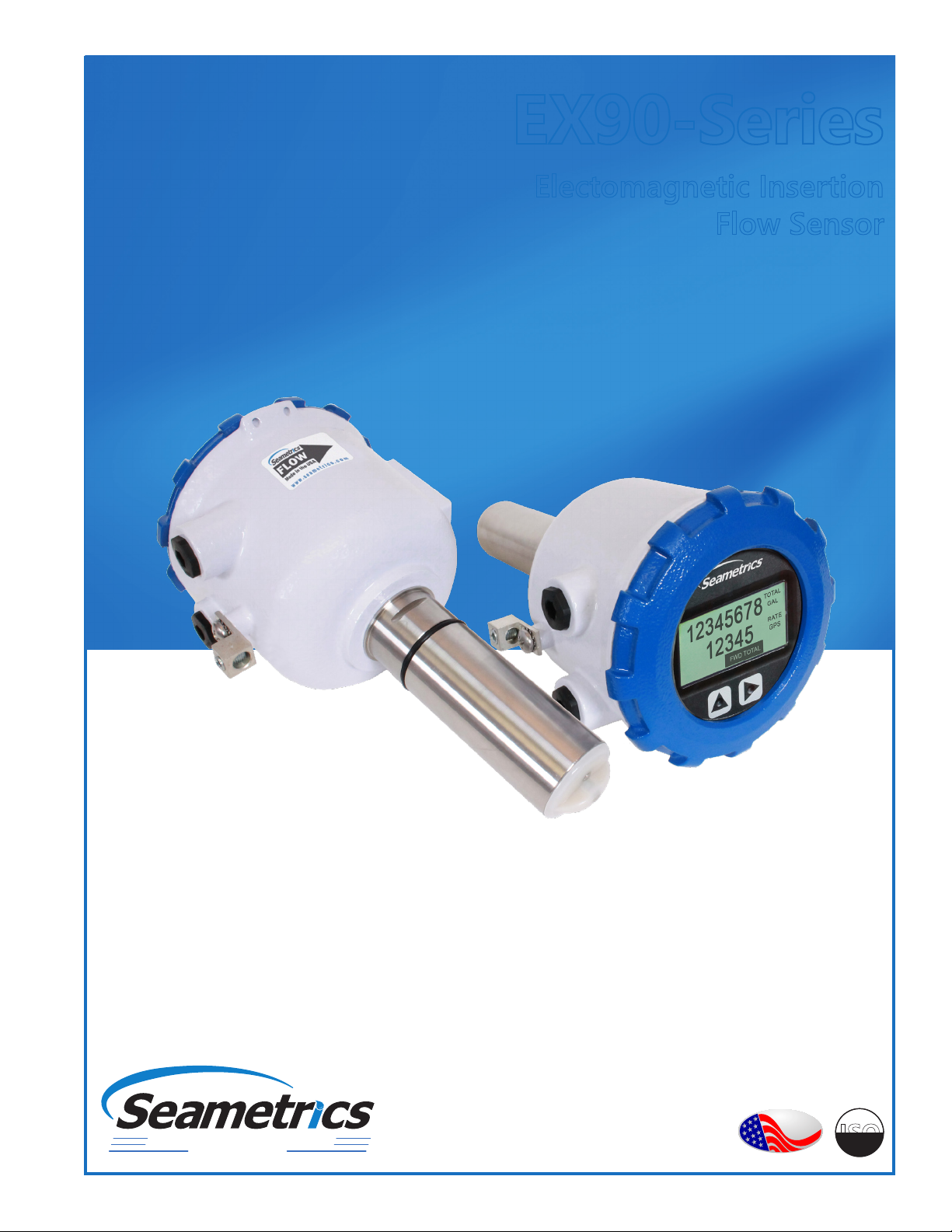
EX90-Series
Electomagnetic Insertion
Flow Sensor
Precision Flow Measurement
An ON
I
CON Brand
PROUDLY
MADE
IN THE
USA
C
o
d
m
e
i
f
i
t
r
e
C
ISO
9001
p
a
n
y
Page 2

TABLE OF CONTENTS
EX90-SERIES INSTRUCTIONS
General Information
General Information ...................................................................................................................................................Page 3
Features ...........................................................................................................................................................................Page 3
Specications ................................................................................................................................................................Page 4
Flow Rate ........................................................................................................................................................................Page 4
Dimensions ....................................................................................................................................................................Page 5
Installation
Chemical Injection or Fertigation ..........................................................................................................................Page 6
Fitting Installation ........................................................................................................................................................Page 6
Meter Installation ........................................................................................................................................................Page 6
Saddle Installation .......................................................................................................................................................Page 7
Straight Pipe Recommendations ...........................................................................................................................Page 8
Full Pipe Recommendations ....................................................................................................................................Page 9
Connections
General Cable Information .......................................................................................................................................Page 10
Cable Gland Opening and Sealing ........................................................................................................................Page 10
Cable Installation .........................................................................................................................................................Page 10
Wiring Diagrams ..........................................................................................................................................................Page 11
Cable Wiring Table ......................................................................................................................................................Page 11
Conguration
Cable Shield ...................................................................................................................................................................Page 12
Pulse Output ..................................................................................................................................................................Page 12
Operation
Minimum Flow ..............................................................................................................................................................Page 13
Filtering ............................................................................................................................................................................Page 13
Electrode Coating ........................................................................................................................................................Page 13
Changing Flow Meter Settings - Standard Menu Options ..........................................................................Page 13
Changing Flow Meter Settings - Submenu .......................................................................................................Page 13
Changing Flow Meter Settings - Home Screen and General Navigation ..............................................Page 15
Changing Flow Meter Settings - Making Selections......................................................................................Page 15
To Change a Passcode ...............................................................................................................................................Page 16
Power Indicators ..........................................................................................................................................................Page 16
Battery Powered Units ...............................................................................................................................................Page 17
Troubleshooting & Error Messages
Problem ...........................................................................................................................................................................Page 18
Probable Cause.............................................................................................................................................................Page 18
Things to Try ..................................................................................................................................................................Page 18
Error Messages .............................................................................................................................................................Page 19
Seametrics • 253.872.0284 Page 2 seametrics.com
Page 3
GENERAL INFORMATION
EX90-SERIES INSTRUCTIONS
The EX90-series battery powered, insertion electromagnetic
ow meter is designed for use with conductive uids in 4”–
12” pipe. The EX90’s stainless steel body allows the meter
to operate in a wide range of temperatures, pressure, and
corrosive or dirty environments.
The EX90 is highly suitable for dicult applications. With
no moving parts, these meters can be used in “dirty water”
applications where debris would foul a mechanical meter. If
the EX90 meter is used with a programmable controller, the
output signal can be fed direct, with no other conditioning
required.
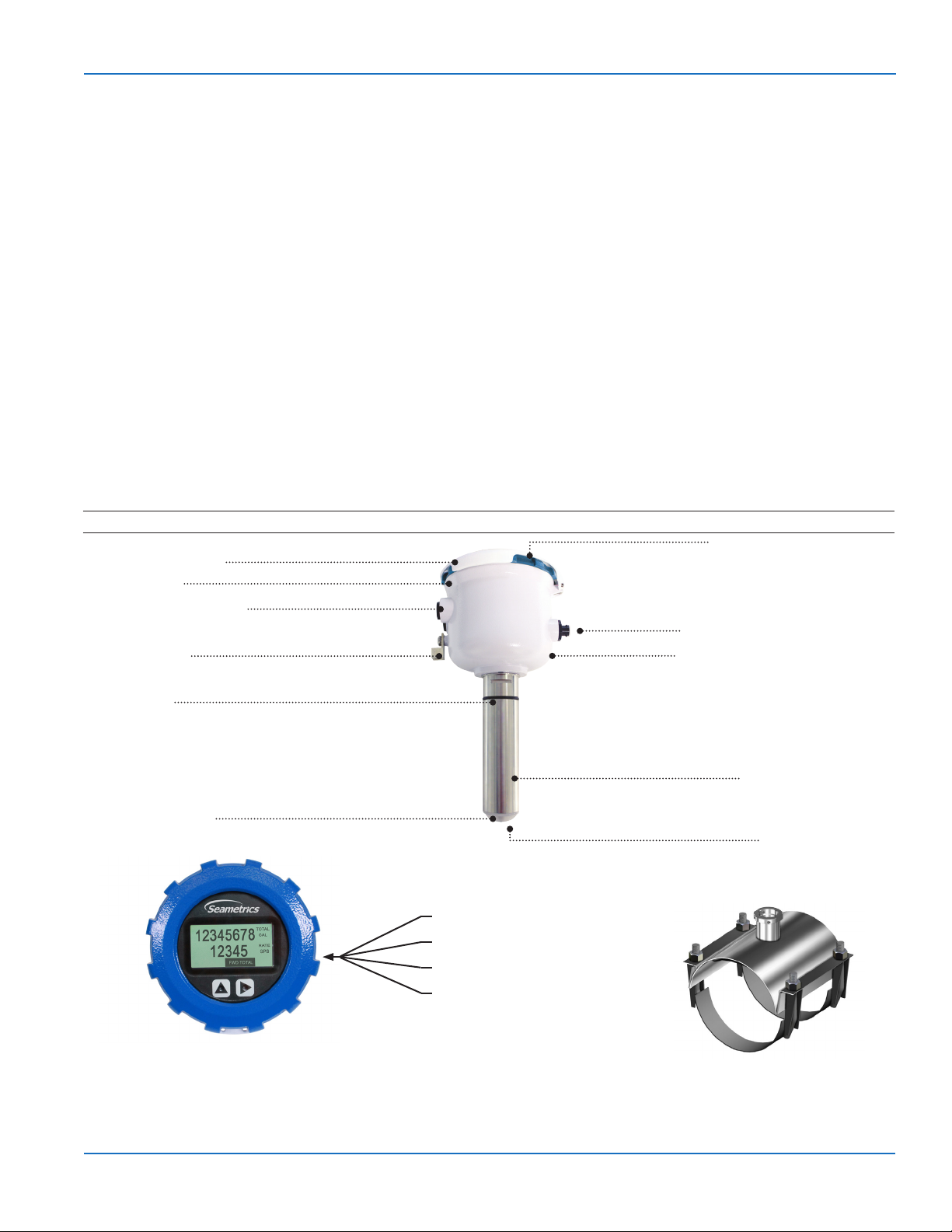
Features
Hinged Display Cover
User access lid
Output cable port access
Rate and total units can be set via the front panel touch key
pad by the user. Bidirectional ow is standard with totals
available in forward, reverse, net, batch forward and batch
reverse.
The EX90 is battery powered and an output cable is
available for transmitting the pulse signal to remote
devices. The EX90 includes a Seametrics saddle which has
been designed to accommodate a wide range of pipe sizes
and types while ensuring correct placement in the pipe.
In addition, an optional internal data logger allows local
storage of ow history.
Rate and total indicator with
light sensor button controls
Data logger connector (optional)
Equalization lug
O-ring, EPDM
PVDF electrode cap
Quickly and easily change Total Volume Units,
Flow Rate Units, Pulse Output Scaling, and many
other settings using the two light sensor button
controls on the display panel.
Powder-coated diecast aluminum
electronics housing
Sensor body (Stainless)
Hastelloy electrodes
Battery Power
Bidirectional Flow Reading
Pulse Scaled Output
Built-in Data Logger (Optional)
Saddle Included
Seametrics • 253.872.0284 Page 3 seametrics.com
Page 4

GENERAL INFORMATION
EX90-SERIES INSTRUCTIONS
Specications*
Pipe Size 4” to 12”
Materials Sensor Body 316 SS
Electrodes Hastelloy
Housing Powder-coated diecast aluminum
Electrode Cap PVDF (Kynar®)
O-Ring EPDM
Temperature Ambient
Temperature
Fluid Temp. 32˚ to 200˚ F (0˚ to 93˚ C)
Pressure 200 psi (14 bar)
Flow Rate 0.5 - 4.5 m/sec (1.64 - 14.8 ft/sec) (Low ow cuto .15 m/sec; .49 ft/sec)
Calibration
Accuracy
0.5 - 4.5 m/s
(1.64-14.76 ft/sec)
0.3 - 0.5 m/sec
(0.98 - 1.64 ft/sec)
Display Type 128x64 dot-matrix LCD
Digits 5 Digit Rate 8 Digit Total
Units
Please Note:
All meters are factory
set for gallons per
minute (GPM) rate and
acre foot total. If other
units are required, they
can be set in the eld.
Bidirectional Forward Total, Reverse Total, Net Total, Batch Forward, Batch Reverse
Power One lithium 7.2V ‘D’ size battery pack, replaceable.
Scaled Pulse
Output
Signal Current sinking pulse, isolated, 36 Vdc at 10 mA max
Pulse Rates User-scalable from 0.1 to 99,999.9 volume units/pulse. Pulse width varies with output frequency, 150
Cable Optional Output
Cable
Conductivity >20 microSiemens/cm
Empty Pipe Detection Hardware/software, conductivity-based
Regulatory
Environmental IP68
* Specications subject to change. Please consult our website for the most current data (seametrics.com).
1
Rate Time Unit is available in Day only.
Kynar is a registered trademark of Arkema, Inc.
Flow Rate (4” - 12”)
0˚ to 160˚ F (-17˚ to 72˚ C)
+/- 2% of reading
+/- (2% of reading + 0.25% of full scale)
Rate Volume Units Rate Time Units Total Volume Units
Gallons
Liters
Barrels (42 gallons)
Cubic Feet
Cubic Meters
Million Gallons
Mega Liters
1
1
Imperial Gallons
Million Imperial Gallons
1
Second
Minute
Hour
Day
Gallons
Gallons x 10
Gallons x 100
Gallons x 1000
Million Gallons
Liters
Kilo Liters
Mega Liters
Barrels (42 gallons)
Cubic Meters
pulses/sec max
20ft (6m) standard length polyurethane jacketed cable—for power and outputs.
(Lengths up to 200’ (60 m) available.)
(EN 61326) Pending
Cubic Meters x 1000
Cubic Feet
Cubic Feet x 1000
Million Cubic Feet
Imperial Gallons
Imperial Gallons x 1000
Million Imperial Gallons
Acre Inch
Acre Foot
Fluid Ounce
FLOW
Nominal Pipe Size
Low Flow Cuto GPM
Low Flow Cuto LPS
Min GPM
Min LPS
Max GPM
Max LPS
4” 6” 8” 10” 12”
19.3
1.22
64.3
4.1
578
36.5
43.11
2.72
144.6
9.1
1301
82.1
77.1
4.86
257
16.2
2313
145.9
120.5
7.6
401.6
25.3
3614
228
173.5
10.95
578.3
36.5
5204
328.3
10x/5x
Pipe Diameter
2x
Pipe Diameter
Upstream straight pipe is selected during initial setup. Upstream
options are 5X or 10X the diameter and are based on the
amount of straight pipe available in either new or propeller meter
replacement installation. Downstream straight pipe requirement
is 2X the diameter. See programming setup for details.
Seametrics • 253.872.0284 Page 4 seametrics.com
Page 5
GENERAL INFORMATION
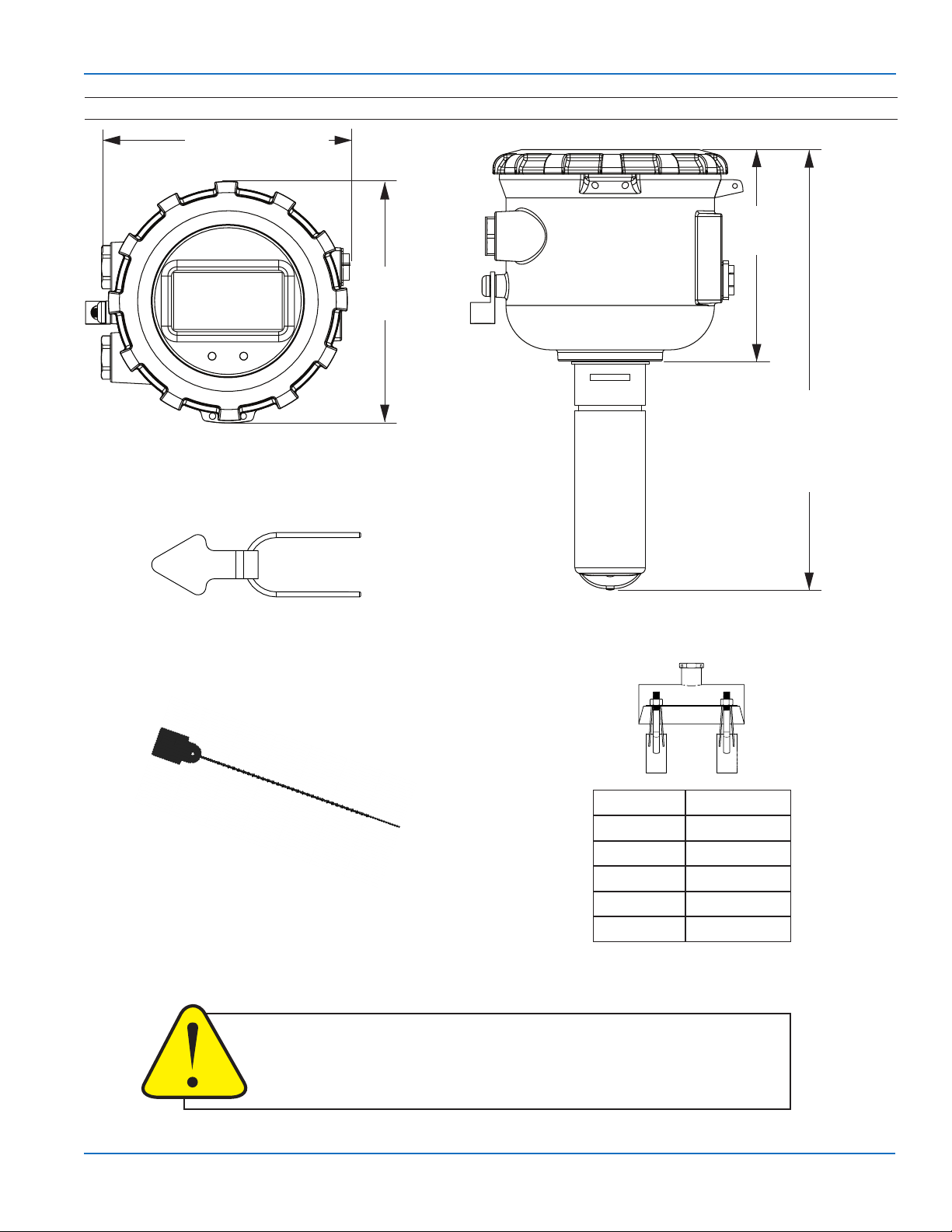
Dimensions
5.48 in (13.92 cm)
EX90-SERIES INSTRUCTIONS
4.76 in
(12.09 cm)
5.28 in
(13.41 cm)
Top of Saddle
EX90-0400 - 10.40 in (26.42 cm)
EX90-0600 - 11.14 in (28.30 cm)
EX90-0800 - 11.86 in (30.12 cm)
EX90-1000 - 12.60 in (33.73 cm)
EX90-1200 - 14.29 in (36.30 cm)
Attach U-clip retainer during installation
Attach display security seal during
installation if regulations require.
CAUTION: Ensure that the U-clip is installed and never remove the U-clip
retainer when the pipe is under pressure. Always remove pressure from
the pipe before you attempt to remove the meter. Removal under pressure
may result in damage or serious injury.
Saddle Size Range
4” 4.00”- 4.90”
6” 6.00”- 6.90”
8” 8.00” - 9.05”
10” 10.40” - 11.10”
12” 12.10” - 13.20”
Consult factory if your OD
does not match.
Seametrics • 253.872.0284 Page 5 seametrics.com
Page 6

INSTALLATION
Fitting Installation
EX90-Series meters require special saddles that ensure
that the ow sensor is installed to the correct depth. The
saddle must be installed in the pipeline before the meter
can be installed. For best results, see straight pipe and full
pipe information on pages 8 and 9.
If there is not enough straight run to smooth out the
turbulence caused by valves, ttings, and changes in
direction, some decrease in accuracy may result. This does
not mean that the ow meter’s reading is meaningless
however. In some applications (control systems, valve
operation, chemical addition) a repeatable reading may
be more important than a highly accurate one.
EX90-SERIES INSTRUCTIONS
Side (3 o’clock), top (12 o’clock) installations are acceptable.
Orienting the Meter
FLOW
10X/5X
Upstream straight pipe is selected during initial setup. Upstream
options are 5X or 10X the diameter and are based on the amount of
straight pipe available in either new or propeller meter replacement
installation. Downstream straight pipe requirement is 2X the diameter.
See programming setup for details.
.
Meter Installation
After the saddle is installed in the pipeline, the meter can
be installed in the tting. After noting the direction of the
ow arrow, press the meter into the tting as far as it will
go. Retain the meter in place by inserting the U-clip. The
pin can be installed from either side. It may be necessary
to rotate the probe back and forth slightly to start the pin
into the slots on the probe. Slide the pin in as far as it will
go.
2X
Chemical Injection
When any magmeter, by any manufacturer, is used in a
chemical injection application (including fertigation), the
chemical injection point must be placed downstream of
the magmeter OR far enough upstream for complete
mixing to occur before the uid reaches the meter. When
unmixed chemical or fertilizer alternates with water passing
through the meter, the rapid changes in conductivity may
cause sudden spikes and drops in the meter’s reading,
resulting in inaccurate measurement. The magmeter will
restabilize, however, with a steady ow of uid of uniform
conductivity.
Caution: In chemical injection
applications, install chemical injection
point downstream of magmeter, or far
enough upstream to allow complete
mixing of uids before the meter.
Seametrics • 253.872.0284 Page 6 seametrics.com
Page 7

New Installation
BEFORE INSTALLING measure & record inside diameter (ID) of pipe.
EX90-SERIES INSTRUCTIONS
1. Clean the mounting surface, remove
any roughness from the area.
4. Place saddle top over gasket. Make sure
saddle top covers entire gasket. Place the
saddle clamps under the pipe and align
with the clamp guides on the saddle top.
Propeller Replacement Installation
2. Cut a 1.75” hole into pipe. 3. Place gasket centered over pipe opening.
5. Place saddle plates over saddle
clamp threads. Attach nuts and
tighten as shown below. Torque to
6. Insert the EX90 sensor into the saddle
tting and secure with mounting clip or
attach security clip and seals if required.
75 ft-lb in cross pattern.
th
4
nd
2
st
1
rd
3
BEFORE INSTALLING measure & record inside diameter (ID) of pipe.
1. Clean the mounting surface, removing any roughness which would prevent
the gasket from sealing. Place gasket
centered over pipe opening.
4. Place the saddle clamps under the
pipe and align with the clamp guides
on the saddle top.
2. Place saddle top over gasket. 3. Make sure saddle top covers entire
gasket.
5. Place saddle plates over saddle
clamp threads. Attach nuts and
tighten as shown below. Torque to
6. Insert the EX90 sensor into the saddle
tting and secure with mounting clip or
attach security clip and seals if required.
75 ft-lb in cross pattern.
th
4
st
1
nd
2
Seametrics • 253.872.0284 Page 7 seametrics.com
rd
3
Page 8

INSTALLATION
Grounding
EX90-SERIES INSTRUCTIONS
Electronically Noisy Installations. When the EX90 is
installed in an electrically noisy system (near a VFD etc.),
grounding is recommended. Where lightning is a threat, or
in severe electrical environments, an optional connection to a
nearby equipment ground or ground rod is advisable.
Straight Pipe Recommendations (X = diameter)
Two Elbows In Plane
Equalization Lug
#6, #8, or #12 AWG Stranded
Copper Ground Wire < 5’
Ground Clamp
(Exothermically weld when
corrosion is a concern)
Earth
8’ Ground Rod
Full Pipe Recommendations
Possible Problem
Can create air pocket at sensor
10X/5X
2X
Pipe conguration selected during program setup.
Better Installation
Allows air to bleed o
Seametrics • 253.872.0284 Page 8 seametrics.com
Page 9

INSTALLATION
Full Pipe Recommendations
Allows air pockets to form at sensor Ensures full pipe
EX90-SERIES INSTRUCTIONS
Better InstallationPossible Problem
Better InstallationPossible Problem
Post-valve cavitation can create air pocket Keeps pipe full at sensor
Better InstallationPossible Problem
Air can be trapped Allows air to bleed o
Seametrics • 253.872.0284 Page 9 seametrics.com
Page 10

CONNECTIONS
EX90-SERIES INSTRUCTIONS
EX90 General Cable Information
In the EX90 meter, there are two output cable ports. Either
port can be used. The cable contains the wires for scaled
pulse output and optional external DC power. See Sample
Cable Wiring Diagrams and Wiring Table.
Power/Output Cable
The EX90 is available as a Battery powered meter
EX90 Cable Installation (Wiring)
Battery Version with external pulse output.
1. Unscrew the display lid and remove it.
2. Remove the display assembly from the
meter exposing the internal connectors.
Be sure NOT to undo any connections to
the display assembly as you remove it.
3. There is a two 2-pin connector already
installed.
4. Remove the plug and o-ring from the cable port(s)
where you want to insert the cable.
5. Install cable gland and insert cable end.
6. Strip cable jacket and conductors and install the wires
into the connectors in their respective locations. (See
Cable Wiring Table for details.)
7. Plug the battery cable into the circuit board, as shown:
Battery
connection
Battery version with two 2-pin connectors
Battery Version with no external pulse output
No wiring is needed.
Cable Gland Opening and Sealing
WARNING: Improper sealing of glands or cables will invalidate any warranty.
8. Secure the cables inside the internal strain relief clip
and tighten the cable gland sealing nut securely.
(torque nut to 22 in-lbs.). A loose nut could cause
moisture ingress and compromise the meter head’s
IP67 rating, voiding the warranty.
9. Remount the display assembly, being careful to not
pinch any wires.
10. Reinstall the display lid, being sure to avoid crossthreading. Ensure the lid is screwed down fully to
prevent water ingress.
Remove plug & o-ring. Insert
cable gland/strain relief. Feed
cable through cable gland.
Seametrics • 253.872.0284 Page 10 seametrics.com
Clamp cable with strain relief
clips. Attach drain wire lug to
bracket post.
CRITICAL!
Torque cable gland sealing
nut to 22 in-lbs.
Page 11

CONNECTIONS
Black (C1) DC-
EX90-SERIES INSTRUCTIONS
EX90 Wiring Diagrams
Unscrew the display lid and remove it from the meter. Unsnap the display assembly and remove it from the meter
exposing the internal wiring connector. Install the wires through the cable glands into the 2 pin screw connector.
C1 = Power/Output cable)
C1
White (C1) PulseGreen (C1) Pulse+
With Pulse Output Only
With No External Output
C1
White (C1) PulseGreen (C1) Pulse+
Pulse with External Power
Red (C1) DC+
NOTE:
If not using external output,
no wiring is required.
EX90 Cable Wiring Table
PIN 1 PULSE SCLD - 2 PULSE SCLD + PWR - PWR +
Battery
Powered
Meter
Externally
Powered
Meter
Seametrics • 253.872.0284 Page 11 seametrics.com
WHITE
C1
WHITE
C1
GREEN
C1
GREEN
C1
(C1 = Power/Output Cable 1)
BLACK
C1
NOT USED
RED
C1
Page 12

CONFIGURATION
EX90-SERIES INSTRUCTIONS
Cable Shield. In general, the cable shield and its bare drain
wire should be left unconnected at the user equipment end
of the cable to minimize “ground loop” problems.
Pulse Output Conguration. A pulse output is standard
on all models. Since this is an isolated output, the external
equipment must include a DC power source to regenerate
the pulse from the open-collector output (transistor
equivalent of a contact closure). A pull-up or pulldown resistor may be needed if not included in the user
equipment. Both the power source and resistor may be
supplied internally in some types of control and monitoring
devices. If not, as for most PLC discrete input modules, they
must be added externally at the module input terminals.
The pulse output rate in volume units/pulse can be set by
the user via the SETP tab on the meter’s setup menus.
Because the pulse output of an EX90 meter is set by the
user, care must be taken to assure the output pulses do not
exceed the maximum frequency of the meter while also
ensuring a reasonable resolution.
K-factor: Remember that SETP is expressed in units totaled
per output pulse (G/P if using gallons) while K-factors
are expressed in pulses per gallon (P/G.) To determine
K-factor from SETP, divide 1 by SETP (if SETP is expressed in
gallons.) Conversely, 1 divided by the K-factor equals SETP
Because all pulse outputs (SETP) are congured in (rate)
units totaled per pulse, all sizes of meters can be congured
with the same SETP values
For example, if your rate is chosen as gallons per minute
(GPM) the table below applies. If your rate is dierent,
simply use your rate label in place of (GPM.) The numerical
values will remain the same.
SETP
0.1 6 900
0.2 12 1800
0.3 18 2700
0.4 24 3600
0.5 30 4500
0.6 36 5400
0.7 42 6300
0.8 48 7200
0.9 54 8100
1.0 60 9000
Flow Rate at 1 Hz
(GPM)
Flow Rate at 150 Hz
(GPM) Battery Powered
Meters
Lower frequency output pulses (1 pulse for some particular
number of gallons) can also be set.
EX90 battery powered units have a maximum output
frequency of 150 Hz.
Pulse Units. The units of measure of SETP are independently
selectable and are not tied to rate or total. Upon change of the
SETP unit, the pulse output may take up to 10 seconds, or the
duration of one pulse (whichever is longer) to take eect.
If Pulse Output is Inconsistent. The DAMP lter may need
to be increased.
Pulse Width Timing. The unit and value of SETP must be
chosen to keep the duration between meter pulse outputs to
less than 500 seconds.
Pulse Timing in Battery Powered Units. The output pulse
width in battery powered units is short and varies with pulse
frequency. (See table)
Any output frequency can be determined by:
Rate (units/minute) ÷ SETP (units/pulse) = pulse/minute
Hz = pulse/minute ÷ 60 seconds / minutes
Output Pulse Width of Battery Powered Units
Output Pulse Width as a Percentage of
Output Pulse Frequency
Zero to 1 Hz
>1 to 20 Hz
>20 to 100 Hz
>100 to 150 Hz
Example: If frequency = 20 Hz then the pulse period = 50 milliseconds and pulse
width = (.05 x 50 milliseconds) = 2.5 ms
(Pulse period = 1000 milliseconds/fre-
Multiply the pulse
period by 0.01
Multiply the pulse
period by 0.05
Multiply the pulse
period by 0.1
Multiply the pulse
period by 0.15
the Pulse Period
quency)
= Output Pulse
Width (ms)
= Output Pulse
Width (ms)
= Output Pulse
Width (ms)
= Output Pulse
Width (ms)
Seametrics • 253.872.0284 Page 12 seametrics.com
Page 13

OPERATION
EX90-SERIES INSTRUCTIONS
Minimum Flow
As with any other ow sensor, there is a rate below which
the EX90-Series sensor cannot read. Check the table below
(also on page 4) for the minimum ow rate detectable by
the sensor for a given pipe size.
Nominal Pipe Size
Low Flow Cuto GPM
Low Flow Cuto LPS
Min GPM
Min LPS
Max GPM
Max LPS
4” 6” 8” 10” 12”
19.3
1.22
64.3
4.1
578
36.5
43.11
2.72
144.6
9.1
1301
82.1
77.1
4.86
257
16.2
2313
145.9
120.5
7.6
401.6
25.3
3614
228
173.5
10.95
578.3
36.5
5204
328.3
Standard Menu Options
T UNIT
View or change TOTAL
volume units
T UNIT R UNIT SET P DAMP
TOTAL = GALLONS
PRESS + TO SET TOTAL
UNITS FOR DISPLAY
EXIT
Filtering
The software of the EX90-Series lters out electrical noise
and averages sudden variations in the ow to smooth the
output. It takes a matter of seconds for the ow sensor to
get up to full output after ow begins.
Electrode Coating
Grease or other adhering, non-conductive materials can
stop ow detection if the electrodes become heavily
coated. To clean the electrodes, remove the sensor from
the pipe and gently wipe o the electrodes (three silver
bumps) on the reading face of the ow sensor. A mild soap
(dish washing liquid for example) can be used to aid the
cleaning process.
SET P
View or change pulse
output scaling
T UNIT R UNIT SET P DAMP
00001.0 GALLONS
PRESS + TO SET
GALLONS TOTALIZED PER
PULSE SENT OUT PULSE1
EXIT
R UNIT
View or change ow
RATE units
T UNIT R UNIT SET P DAMP
FLOW RATE = GALLONS/MIN
PRESS + TO SET RATE
UNITS FOR DISPLAY
EXIT
Special SUBMENU for Further Options
The EXIT tab in the MAIN MENU has a second function. If,
instead of using the hold and tap sequence to return to the
HOME screen, you tap ve times, you will be redirected
to a SUBMENU screen from which you can access several
more options.
Navigation in this SUBMENU is the same as for the MAIN
MENU. Whenever you wish, go to the EXIT tab in the
SUBMENU and perform the hold and tap sequence to
return to the MAIN MENU.
DAMP
View or change # of
sample periods for
rolling average.*
(0=1 sample period,
1=2 sample periods, etc.)
T UNIT R UNIT SET P DAMP
DAMPING = 1
PRESS + TO SET
DAMPING VALUE
EXIT
* See DAMP Settings for Battery Units on page 16.
INFO: Meter model number, serial number, and
rmware version.
SAMP: Sample rate.
SETUP: View or change pipe settings.
EXIT: Return to MAIN MENU.
INFO COMM MBID FL DIR
PRESS + TO VIEW INFO
ABOUT METER
SAMP
HPOLL SETUP EXITSAMP
Sub-Menu - Battery Only Version
Seametrics • 253.872.0284 Page 13 seametrics.com
Page 14

OPERATION
Initial Setup
INITIAL SETUP OF ID, HOLE, AND PIPE IS
REQUIRED FOR THE METER TO OPERATE
PROPERLY.
When you remove the meter from the box, it will prompt
you to perform initial SETUP of ID, Hole and PIPE before
you can proceed to other menu functions or return to the
HOME screen.
EX90-SERIES INSTRUCTIONS
the pipe size. These are considered “LARGE” holes. In this
type of installation, the meter has signicant room between
it and the hole cut into the pipe. When water ows by the
meter, it lls this extra cross sectional area while owing
past the measurement point. This means that unlike the
“SMALL” hole case, the cross sectional area at the point
of measurement is not equal to the I.D. of the pipe. When
this menu is selected, the EX90 will compensate for this
condition.
SETUP Menu Functionality
The SETUP menu works slightly dierently than other
menus inside the EX90. The black square highlighting the
left most text is similar to a cursor on a computer. It lets
you know where you are within the menu. Press Up 1x
and the menu category will change. The categories are as
follows:
ID (Internal Diameter in inches)
HOLE (Hole Size Cut into Pipe for Inserting Meter)
PIPE (Piping Conguration Selection)
ID
The Internal Diameter (or I.D.) of the Pipe in which the EX90
is installed is critical to the meter’s performance. The EX90
senses a local velocity around the electrodes and uses that
information to extrapolate the ow over the entire pipe
section. The ID is also used ‘under the hood’ to scale many
critical values such as Low Flow Cuto, Max Flow Rate, etc.
The installer should measure the ID in the most accurate
way possible prior to saddle installation.
HOLE
PIPE
The PIPE menu is used to compensate for altered velocity
proles in various piping congurations. When obstructions
or disturbances are introduced to straight pipe (particularly
upstream of the meter), the velocity prole changes shape.
Since the AG90 measures a relatively small cross section of
the velocity prole, large distortions of this prole can lead
directly to measurement error. The pipe menu has distinct
pipe conguration compensation built into the AG90
allowing you to select the closest condition to your actual
pipe and allows the AG90 to operate at peak performance.
STRAIGHT
Straight Pipe is a relative term. For this conguration, the
EX90 considers the pipe to be straight if there are 20+
diameters of straight pipe upstream from the meter and
at least 2 diameters downstream from the meter from any
obstruction in the pipe.
10/2 ELB
This selection represents an install condition in which there
exists a single in plane elbow 10 diameters upstream from
the meter and 2 diameters downstream from the meter.
HOLE references dierent types of installs:
SMALL
5/2 ELB
This selection represents an install condition in which there
exists a single in plane elbow 5 diameters upstream from
New Installations will cut a 1.75” hole into the pipe. This is
the meter and 2 diameters downstream from the meter.
considered a “SMALL” hole. In this type of installation, the
meter is ush to the diameter of the hole. This represents
an ideal installation condition, because the cross-sectional
area at the measurement point is equal to the I.D. of the
pipe.
LARGE
ADJ
The adjustment menu is for installers and regulating
bodies. This menu allows manual adjustment of the rate
(on a % of reading basis) in installations outside of the
scope of this document. This menu should be used when
a known reference is temporarily (or otherwise) installed
Retrot installations already have a hole cut into the pipe.
Typically they are quite large (especially when replacing
into the system and adjustment can be made with high
condence and reliability.
mechanical meters), although the exact size depends on
Seametrics • 253.872.0284 Page 14 seametrics.com
Page 15

OPERATION
1.2345678
TAP
TAP
1.2345678
100
TOTAL
CU FT
X1000
RATE
GPM
FWD TOTAL
1.2345678
100
TOTAL
CU FT
X1000
RATE
GPM
T UNIT R UNIT S ET PDAMP
SET 4
SET 20 EXIT
TOTAL = GALLONS
PRESS + TO SET TOTAL
UNITS FOR DISPLAY
FWD TOTAL
TAP
TAP
TAP
TAP
+
HOLD TAP
+
HOLD TAP
Changing Flow Meter Settings
EX90-SERIES INSTRUCTIONS
Home Screen and General Navigation
The HOME Screen displays ow volume, direction of the
ow total and ow RATE along with status conditions such
as Empty Pipe. Two buttons below the LCD display are used
to access menu screens for viewing and changing meter
setup parameters.
TOTAL
CU FT
X1000
RATE
100
FWD TOTAL
GPM
These two buttons are light sensors which can detect
when a nger is covering them and operate upon release.
Only three button touch actions are needed to control
navigation through the menus, settings changes and back
to the home screen.
HORIZONTAL SCROLLING:
Tap right button to scroll horizontally through
menu tabs or move horizontally within a tab
dialog when applicable.
Making Selections
Once in the Menu System, move from tab to
tab by tapping the right button. (See the next
page for details on the various available tabs.)
Select the parameter. In the screen for
the highlighted tab you will see the current
parameter value for that tab. Tapping the right
button, move to the tab for the parameter you
want to change.
In this example, the rst line indicates that the
current unit for the TOTAL is GALLONS. The
next two lines tell you what to do next.
T UNIT R UNIT S ET PDAMP
TOTAL = GALLONS
PRESS + TO SET TOTAL
UNITS FOR DISPLAY
SET 4
SET 20 EXIT
If you would like to change the TOTAL units,
just perform the hold and tap sequence to
bring up a screen to change the setting.
+
HOLD TAP
VERTICAL SCROLLING:
Tap left button to change a highlighted item
within a tab dialog.
SELECT/ENTER/EXIT:
Hold left button while tapping right button
once to enter or exit a tab dialog or to
navigate between the HOME and other
menu screens.
To enter the Menu System perform the hold
and tap sequence. The Passcode entry screen
will display. The default passcode is 000000. If
a dierent passcode has previouly been set,
use the and to enter that passcode.
In either case, hold and tap again to move
passcode, hold and tap again to return to the
previous screen. See page 16 for information on
how to change a passcode.)
into the menu system. (If you enter the wrong
ENTER PASSCODE
T UNIT R UNIT S ET PDAMP
TOTAL:
PRESS TO CHANGE
SET 4SET 20 S ET F EXIT
GALLONS
Scroll through setting. Select the new setting
by scrolling through a list of selections by
tapping the left button to nd a dierent
TOTAL unit.
Accept changes. To accept any changes
you have made, perform the hold and tap
sequence.
When nished making changes. When you
are nished making changes, move to the EXIT
tab using the right button.
+
HOLD TAP
Seametrics • 253.872.0284 Page 15 seametrics.com
000000
PRESS AND TO CHANGE
To return to the HOME screen, perform the
hold and tap sequence.
+
HOLD TAP
Page 16

OPERATION
1.2345678
100
TOTAL
CU FT
X1000
RATE
GPM
FWD TOTAL
LO
1.2345678
EX90-SERIES INSTRUCTIONS
To Change a Passcode and Decimal Places
The EX90 has a passcode system for restricting access to the
menus. The EX90 comes from the factory with the passcode
set to 000000. When a user attempts to enter the menu system
(see details on page 14), the passcode entry screen will be
displayed.
The default passcode is 000000. If a dierent passcode has
previously been set, then the user must enter that passcode at
this time. After entering the passcode, or leaving it at 000000
if using the default passcode, the user does the hold and tap
sequence to move into the menu system.
To change the passcode, you must use the THIRD MENU
screen. Access the THIRD MENU screen as follows:
• Enter the main menu system, as described above.
On the main menu, tab over to the EXIT tab and tap the up
arrow ve times. A SUBMENU screen will display.
• On the SUBMENU screen tab over to the EXIT tab and
• To set the code, hold and tap SETCD and then use the
• Hold and tap again to return to the THIRD MENU screen.
• Tab to EXIT, and then hold and tap to return to the
To change the number of decimal places in the total
• To set the decimal point, hold and tap on SETD and then
• Hold and tap again to return to the THIRD MENU screen.
• Tab to EXIT, and then hold and tap to return to the
ENTER PASSCODE
000000
PRESS AND TO CHANGE
T UNIT R UNIT SET PDAMP
TOTAL = GALLONS
PRESS + TO SET TOTAL
UNITS FOR DISPLAY
SET 4
SET 20 S ET F EXIT
INFO COMM MBID FL DIR
PRESS + TO VIEW INFO
ABOUT METER
SAMP
SAMP SETUP EXIT
tap the up arrow ve times. The THIRD MENU screen
will display.
SETD
PLMIN
FOUT EXIT
TEST
SETCD
000000
PRESS + TO SET
PASSCODE
SAMP
and to enter the new code.
SUBMENU.
use the to move the decimal point.
SUBMENU.
Power Indicators
A power indicator is displayed in the lower left of the main
display window.
When powered by battery a battery icon will display.
OK on the battery indicator means battery voltage is above
6.4 volts.
LO on the battery indicator means the battery is low and
should be replaced soon.
Powered by battery -
voltage is sucient
Powered by battery voltage is low
100
P
OK
FWD TOTAL
TOTAL
CU FT
X1000
RATE
GPM
OK
LO
PLMIN
PLMIN is a measure of stability within the lter. Its setting
is in terms of a percentage subtracted from 100. When
PLMIN = 0, the DAMP lter will be applied regardless of
changing ow rates. No amount of ow rate changes seen
by the meter will restart the DAMP lter.
When PLMIN is ≠ 0, PLMIN is subtracted from 100. The
resulting percentage is used as a DAMP lter restart
condition. When this condition is met, the DAMP lter will
be emptied and restarted with fresh data. For instance,
when PLMIN = 25: 100-25=75%. This means that any
reading that diers from its predecessor by 75% or more
(in either the positive or negative direction), will trigger
the DAMP lter reset condition. If PLMIN = 5, the DAMP
lter will only reset when a value is ±95% dierent than its
predecessor.
It is very important to note that PLMIN settings should vary
based upon ow conditions at the install site. If the DAMP
lter is being used to smooth out known varying ow
conditions (pulsating or highly turbulent ows), too high
of a PLMIN value can exacerbate unstable ow conditions.
When ow conditions are such, a value of PLMIN = 0 is
suggested. Note however, that upon startup and shutdown,
this will aect ow rate values responsiveness.
Seametrics • 253.872.0284 Page 16 seametrics.com
Page 17

OPERATION
TEST
TEST allows the user to initiate a fully functional, articial
ow rate for the purpose of testing other connected
equipment. When TEST is applied, all features of the meter
will function at the stated ow rate (in gallons per second).
For TEST to function, the meter must be in water (not
EMPTY PIPE), a rate must be entered and the feature must
be turned ON.
After use, the TEST feature must be turned OFF. If the
TEST feature is not turned OFF, the stated static ow rate
(in gallons per second) will be shown any time the meter is
full or in a owing condition.
Battery Powered Units
To ‘wake up’ a battery powered meter, you may need to
hold the up arrow for 2 seconds and release.
The EX90 meter comes congured with a 7.2V ‘D’ size
lithium battery pack. In this conguration, the only option/
output is the scaled pulse output which comes standard.
Be sure to set your SETP value such that the meter will
function properly over the ow range in your application
(see page 12 for details). The sample rate of the meter is
user selectable through the SAMP tab in the meter’s sub-
menu. Sample periods of 1/5, 1/3, 1, 3, 5, 15, 30, and 60
seconds can be selected. (A sample period of 5 seconds
- 4 year battery life - is the default.)
Larger sample periods will yield longer battery life but
slower response time. Care must be taken to select a
sample period that is suitable for your application. See the
table below for the expected battery life as a function of
sample period.
DAMP/Filtering
The DAMP Filter allows multiple readings to be averaged
over time, thus reducing the meters sensitivity to minor
changes in ow rate. The DAMP Filter is extremely useful for
situations where the ow is not perfectly steady (pulsating
ows, turbulent ows, etc.)
EX90-SERIES INSTRUCTIONS
seconds of data within the lter. This means that the lter
will average readings for 8 seconds prior to displaying a
reading. After the rst reading is displayed, the lter kicks
out the oldest 1 second of data, adds the newest 1 second
of data, recomputes the average ow rate, and displays it
to the screen/output. In this way, it is considered a “running
average”.
SAMP > 1 second
When the SAMP menu is set to a number greater than
1 second, the DAMP menu is dened on a “per reading”
basis. Again, the DAMP lter must always use at least 1
reading to generate a ow rate, so the lter will add 1 to
your selection. For instance, if SAMP is set to 15, and DAMP
is set to 7, the DAMP lter will utilize 7+1=8 readings worth
of data for the lter. This means that the lter will not be
full for 15x8=120 seconds. Note that in most long term
applications, these long lters may be ne, but in shorter
term applications, the DAMP and SAMP menus need to be
adjusted accordingly.
Battery Life/Sample Period
Sensor sample period(s)
Expected battery life*
(Seconds)
1/5 (0.2) 4.5 Months
1/3 (0.33) 7 Months
1 1.5 years
3 3.25 years
5 4 years
15 5.5 years
30 6 years
60 6.25 years
*Based on 85% battery capacity at room temperature.
The DAMP Filter works dierently depending on the SAMP
selection:
SAMP < 1 second
When the SAMP setting is less than 1 second, the DAMP
lter is dened on a “per second” basis. The DAMP lter
always utilizes at least 1 second of data for its lter. Then, it
adds however many seconds you’ve selected in the DAMP
menu setting to that 1 second of data. For instance, if you
set the DAMP menu to 7, your EX90 meter will utilize 7+1=8
Seametrics • 253.872.0284 Page 17 seametrics.com
Page 18

TROUBLESHOOTING & ERROR MESSAGES
Troubleshooting
Problem Probable Causes Things to try…
Blank Display Battery has not been plugged in
Dead battery
Flow rate reading uctuates
excessively when ow is
unchanging
Excessively turbulent or unsteady ow
due to partially closed valves or other
ow obstructions
Plug in the battery
Replace battery
Eliminate or minimize causes of ow disturbances
or increase meter damping
EX90-SERIES INSTRUCTIONS
Flow Rate appears correct but
pulse/ frequency output is low,
erratic or absent
Flow Rate appears correct
but pulse/frequency output is
erratic and/or too high
Flow rate steadily reads
zero when there is ow
Hole reference incorrect or not set.
Straight pipe conguration not set
Pipe not full Provide back pressure or other means to ensure
Pulsing ow due to combining multiple
upstream ow sources
Insucient mixing of upstream chemicals Move chemical injection downstream from meter
Low uid conductivity < 20 µS/cm Replace with dierent type of meter
Noisy electrical environment Improve grounding at meter and nearby
External device input impedance too low
Cable too long
Electrical noise sources interfering with
pulse frequency signal
Wrong type of cable Use only twisted pair cable and ensure both signal
Grounding problem Improve or try dierent grounding method
Pipe ID not set
Flow is below cutoff (very low)
Set correct hole reference
Program straight pipe conguration
pipe is lled
Move connection point further upstream
potentially noisy electrical equipment. Increase
distance between meter and electrical noise
sources.
Use sourcing rather than sinking interface
connection
Reduce interface pull-up resistance
Isolate, remove or reduce noise sources. Move
meter control cable away from noise sources.
wires are on same twisted pair
Program ID of pipe
Reading will resume when ow increases
Flow rate intermittently
Air in the pipe
Air in the pipe Reposition meter for full pipe
Reposition meter for full pipe
drops when there is ow
Jumpy reading Improperly grounded
Pulsing ow
Check for proper grounding
Increase DAMP value
Use external power source
(allows more ow averaging)
Seametrics • 253.872.0284 Page 18 seametrics.com
Page 19

TROUBLESHOOTING & ERROR MESSAGES
EX90-SERIES INSTRUCTIONS
Error Messages
Under certain conditions an error message may be displayed.
Message Description Notes
INIT Initialization is occurring during power up.
EMPTY PIPE Fluid is not detected between the sensing electrodes.
LO in battery icon Battery is getting low, replace soon. Meter still functions. Above 6.4V, OK appears in icon
BATT END Battery is very low (approx. 6.1V). Totalizer stops updating.
COIL FAIL Coil current too high or too low (short or open).
COMM FAIL Communication between transmitter and sensor board fails.
OVER RANGE Rate exceeds number of digits that can be displayed. Adjust units.
Seametrics • 253.872.0284 Page 19 seametrics.com
Page 20

SEAMETRICS LIMITED WARRANTY
The limited warranty set forth below is given by Seametrics, with respect to Seametrics and INW brand products purchased in the
United States of America.
Seametrics warrants that products manufactured by Seametrics, when delivered to you in new condition in their original containers
and properly installed, shall be free from defects in material and workmanship. Seametrics products are warranted against
defects for a period of two (2) years from date of installation, with proof of install date. If no proof of install date can be
provided, warranty period will be two (2) years from date of shipment from Seametrics, as dened on Seametrics’ invoice.
Seametrics’ obligation under this warranty shall be limited to replacing or repairing the part or parts, or, at Seametrics’ option, the
products, which prove defective in material or workmanship. The following are the terms of Seametrics’ limited warranty:
a. Buyer must give Seametrics prompt notice of any defect or failure and satisfactory proof thereof.
b. Any defective part or parts must be returned to Seametrics’ factory or to an authorized service center for inspection.
c. Buyer will prepay all freight charges to return any products to Seametrics’ factory, or another repair facility. as designated by
Seametrics.
d. Defective products, or parts thereof, which are returned to Seametrics and proved to be defective upon inspection, will be
repaired to factory specications.
e. Seametrics will deliver repaired products or replacements for defective products to the buyer (ground freight prepaid) to the
destination provided in the original order.
f. Products returned to Seametrics for which Seametrics provides replacement under this warranty shall become the property
of Seametrics.
g. This limited warranty covers all defects encountered in normal use of Seametrics products, and does not apply to the
following cases:
i. Loss of or damage to Seametrics product due to abuse, mishandling, or improper packaging by buyer
ii. Failure to follow operating, maintenance, or environmental instructions prescribed in Seametrics’ instruction manual
iii. Products not used for their intended purpose
iv. Alterations to the product, purposeful or accidental
v. Electrical current uctuations
vi. Corrosion due to aggressive materials not approved for your specic product
vii. Mishandling, or misapplication of Seametrics products
viii. Products or parts that are typically consumed during normal operation
ix. Use of parts or supplies (other than those sold by Seametrics) which cause damage to the products, or cause
abnormally frequent service calls or service problems
h. A new warranty period shall not be established for repaired or replaced material, products, or supplied. Such items shall
remain under warranty only for the remainder of the warranty period on the original materials, products, or supplies.
i. In the event that equipment is altered or repaired by the buyer without prior written approval by Seametrics, all warranties
are void. Damage caused by equipment or accessories not manufactured by Seametrics may void the product’s warranty.
j. SOFTWARE: The Seller grants the user a non-exclusive license to use Seametrics’ software, according to the following
limitations and conditions:
i. The user may install the software on one or more desktop or laptop computers.
ii. All title and intellectual rights to the software are owned by Seametrics.
iii. No copies may be made or distributed except as described above.
iv. The user may not modify or reverse-engineer the software.
THE FOREGOING WARRANTY IS IN LIEU OF ALL OTHER WARRANTIES, WHETHER ORAL, WRITTEN, EXPRESSED, IMPLIED OR STATUTORY. NO
IMPLIED WARRANTY, INCLUDING ANY IMPLIED WARRANTY OF MERCHANTABILITY OR FITNESS FOR A PARTICULAR PURPOSE, APPLIED TO
THE PRODUCTS AFTER THE APPLICABLE PERIOD OF THE EXPRESS LIMITED WARRANTY STATED ABOVE, AND NO OTHER EXPRESS WARRANTY
OR GUARANTY, EXCEPT AS MENTIONED ABOVE, GIVEN BY ANY PERSON OR ENTITY WITH RESPECT TO THE PRODUCTS, SHALL BIND
SEAMETRICS. SEAMETRICS SHALL NOT BE LIABLE FOR LOSS OF REVENUES, OR PROFITS, OR INCONVENIENCES, EXPENSE FOR SUBSTITUTE
EQUIPMENT OR SERVICE, STORAGE CHARGES, LOSS OF DATA, OR ANY OTHER SPECIAL, INCIDENTAL, OR CONSEQUENTIAL DAMAGE CAUSED
BY THE USE OR MISUSE OF, OR INABILITY TO USE THE PRODUCTS, REGARDLESS OF THE LEGAL THEORY ON WHICH THE CLAIM IS BASED,
AND EVEN IF SEAMETRICS HAS BEEN ADVISED OF THE POSSIBILITY OF SUCH DAMAGES. IN NO EVENT SHALL RECOVERY OF ANY KIND
AGAINST SEAMETRICS BE GREATER IN AMOUNT THAN THE PURCHASE PRICE OF THE PRODUCT SOLD BY SEAMETRICS AND CAUSING THE
ALLEGED DAMAGE. WITHOUT LIMITING THE FOREGOING, YOU ASSUME ALL RISK OF LIABILITY FOR LOSS, DAMAGE, OR INJURY TO YOU AND
YOUR PROPERTY AND TO OTHERS AND THEIR PROPERTY ARISING OUT OF USE OR MISUSE OF, OR INABILITY TO USE THE PRODUCTS NOT
CAUSED DIRECTLY BY THE NEGLIGENCE OF SEAMETRICS.
SOME STATES DO NOT ALLOW LIMITATIONS ON THE DURATION OF AN IMPLIED WARRANTY, SO THE ABOVE LIMITATIONS MAY NOT
APPLY TO YOU. SIMILARLY, SOME STATES DO NOT ALLOW THE EXCLUSION OR LIMITATIONS OF CONSEQUENTIAL DAMAGE, SO THE ABOVE
LIMITATION OR EXCLUSION MAY NOT APPLY TO YOU. THIS LIMITED WARRANTY GIVES YOU SPECIFIC LEGAL RIGHTS; HOWEVER, YOU MAY
ALSO HAVE OTHER RIGHTS WHICH MAY VARY FROM STATE TO STATE.
Seametrics • 19026 72nd Avenue South • Kent, Washington 98032 • USA
(P) 253.872.0284 • (F) 253.872.0285 • 1.800.975.8153 • seametrics.com
LT-14262r2.0 20190404
4/4/2019
 Loading...