

Page 1
EX800-Series
9 001:2008
ISO
ELECTROMAGNETIC FLOW SENSOR INSTRUCTIONS
EX800 SERIES ELECTROMAGNETIC FLOW SENSOR INSTRUCTIONS
CERTIFIED COMPANY
Page 2

TABLE OF CONTENTS
EX800 SERIES INSTRUCTIONS
General Information
General Information, Features .............................................................................................................................Page 3
Specications ........................................................................................................................................................Page 4
Installation
Fitting Installation, Meter Installation, Chemical Injection or Fertigation .........................................................Page 5
Straight Pipe Recommendations .........................................................................................................................
Full Pipe Recommendations .................................................................................................................................Page 7
Electrical Connections
General Electrical Guidelines, Power, Output (Forward Flow and Reverse Flow), Grounding Guidelines .......Page 8
Connections Diagrams
Counter or PLC, A055 4-20 mA Output, FT520 Controller .................................................................................Page 9
FT430/440 Display & Proportional Feed, FT440 & 4-20 mA Output, Dual FT430/440 Displays ..................Page 10
DL76 Data Logger, FT440/DL76 ..........................................................................................................................Page 11
Operation & Maintenance
Zero Adjustment, Minimum Flow, Flow Rate Table,
Filtering, Electrode Coating, Calibration (“K-Factor”), K-Factor Chart ...............................................................Page 12
Exploded Parts View, Parts List ............................................................................................................................Page 13
Page 6
roubleshooting
Problems, Probable Causes .................................................................................................................................Page 14
TABLES AND DIAGRAMS
Features .................................................................................................................................................................Page 3
Specications ........................................................................................................................................................Page 4
Distorted Flows, Orienting the Meter ...................................................................................................................Page 5
Straight Pipe Recommendations .........................................................................................................................
Full Pipe Recommendations .................................................................................................................................Page 7
Grounding Diagram ...............................................................................................................................................Page 8
Connection Diagrams: Counter or PLC, A055 4-20 mA Output, FT520 Controller ...........................................Page 9
Connection Diagrams: FT430/440 Display & Proportional Feed, FT440 & 4-20 mA Output,
Dual FT430/440 Displays .............................................................................................................................Page 10
Page 6
Connection Diagrams: DL76 Data Logger, FT440/DL76 ...................................................................................Page 11
Flow Rate Table, K-Factor Chart ...........................................................................................................................Page 12
Exploded Parts View, Parts List ............................................................................................................................Page 13
Troubleshooting .....................................................................................................................................................Page 14
Page 2
Seametrics • 253.872.0284 • www.seametrics.com
Page 3
GENERAL INFORMATION
EX800 SERIES INSTRUCTIONS
EX800-Series insertion electromagnetic ow meters are
designed for use with conductive liquids in 1 to 12” pipe. A
choice of materials (stainless steel, brass, and PVC) allows
the meter to adapt to a range of temperature, pressure, and
corrosive environments.
The EX800 is highly suitable for difcult applications with
changing viscosities and pulsating ows, such as air-driven
diaphragm pumps. With no moving parts, these meters can
be used in “dirty water” applications where debris would foul a
mechanical meter. Like all magmeters, when used in chemical
injection applications, these meters should be installed
upstream of the chemical line (or far enough downstream to
allow complete mixing of uids before the meter).
Designed for modularity and versatility, the EX800-Series has
a current-sinking pulse output that can be combined with the
appropriate transmitter or indicator for the application. For
Features
basic rate/total and pulse output, the FT430 is best. For
analog output and display of rate and total, the FT440 can be
used. Blind analog output is provided by the AO55. The PD10
can be used to divide the pulse for pacing chemical metering
pumps. Electronic modules can be wall- or meter- mounted.
If the EX800 meter is used with a programmable controller,
the output signal can be fed direct, with no other conditioning
required.
EX800-Series xed depth insertion meters require special
ttings. Factory installation in the tting ensures correct depth
placement in the pipe. The EX800-Series meter can be ordered
in a full power model when a source of electricity is available, or
in a low power model that can run on an external battery with
solar panel.
Reverse ow output and immersibility are optional.
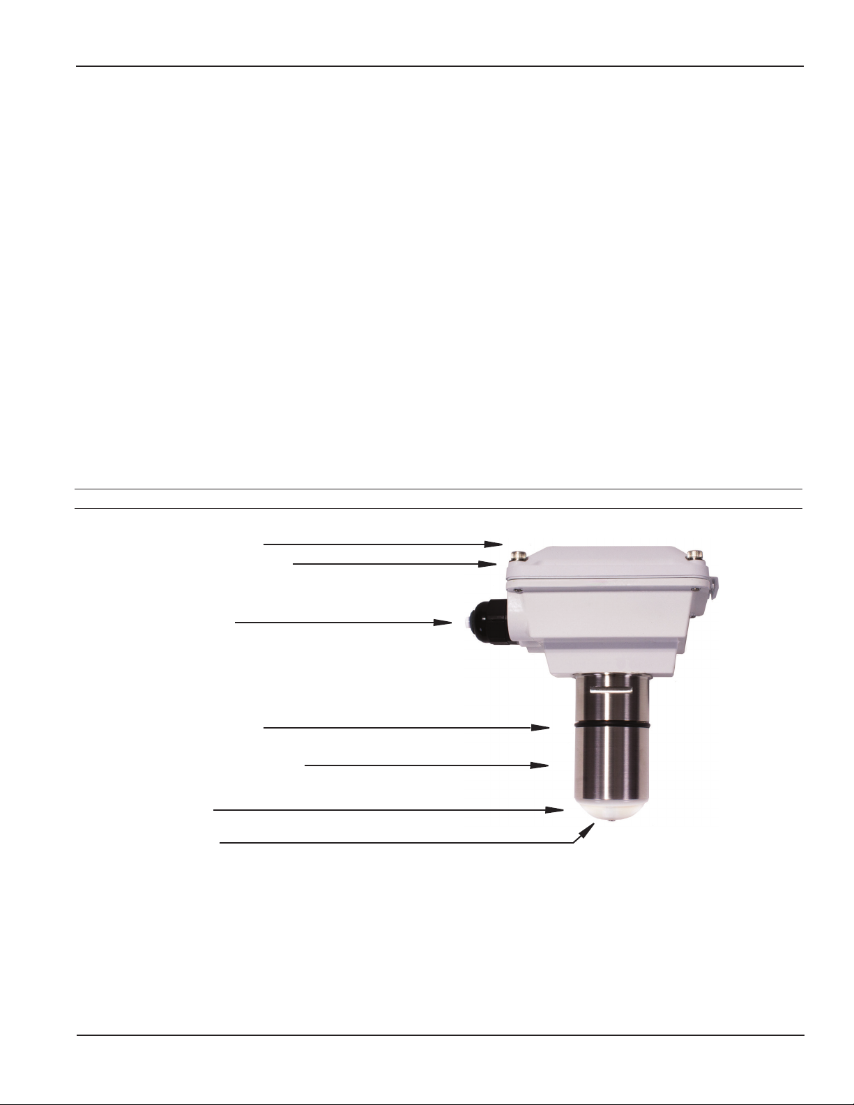
Cover, or electronics module
Powder-coated aluminum housing
Power cord strain relief
O-ring, EPDM (Viton® optional)
Sensor body (Stainless, Brass, PVC)
PVDF electrode cap
Hastelloy electrodes
Seametrics • 253.872.0284 • www.seametrics.com
Page 3
Page 4

GENERAL INFORMATION
Specications*
Pipe Sizes 1” to 12”
Materials Mechanical 316 SS or Brass
Electrodes Hastelloy
Electrode Cap PVDF (Kynar®)
Housing Cast powder-coated aluminum
Valve Assembly (15x/25x only) Bronze (stainless optional) with bronze ball valve
O-Ring (15x/25x only) EPDM standard (Viton® optional)
Power Full Power 12-25 Vdc, 250 mA
Low Power 12-25 Vdc, 40 mA average with 250 mA peaks
Flow Rate 0.28 to 20 ft/sec (0.08 - 6.09 m/sec)
Temperature Ambient 0˚ to 160˚F (-17˚ to 72˚C)
Fluid (Brass/SS) 32˚ to 200˚ F (0˚ to 93˚ C)
Fluid (PVC) 32˚ to 130˚ F (0˚ to 55˚ C) @ 0 psi
EX800 SERIES INSTRUCTIONS
Pressure Brass/SS 200 psi (14 bar)
PVC 150 psi (10 bar) @ 75˚ F (24˚ C)
Minimum Conductivity 20 microSiemens/cm
Calibration Accuracy +/- 1% of full scale
Output Square wave pulse, opto isolated, 500 Hz @ 20 ft/sec
Empty Pipe Detection Software, defaults to zero ow
Regulatory
*Specications subject to change • Please consult our website for current data (www.seametrics.com).
Kynar is a registered trademark of Arkema, Inc., Viton is a registered trademark of DuPont Corporation.
(Standard power only)
Page 4
Seametrics • 253.872.0284 • www.seametrics.com
Page 5
INSTALLATION
Fitting Installation
EX800-Series meters require special ttings that ensure that
the ow sensor is installed to the correct depth. The tting
must be installed in the pipeline before the meter can be
installed. For best results, install with at least ten diameters
of straight pipe upstream of the meter and ve diameters
downstream (or more under specic adverse circumstances).
See diagrams, next page.
EX800 SERIES INSTRUCTIONS
Caution: These ow sensors are not
recommended for installation downstream of
a boiler feedwater pump where installation
fault may expose the ow sensor to boiler
pressure and temperature. Maximum recommended
temperature is 130°F (Plastic), 200°F (Metal).
If there is not enough straight run to smooth out the turbulence
caused by valves, ttings, and changes in direction, some
decrease in accuracy may result. This does not mean that
the ow meter’s reading is meaningless, however. In some
applications (control systems, valve operation, chemical
addition), a repeatable reading may be more important than
a highly accurate one.
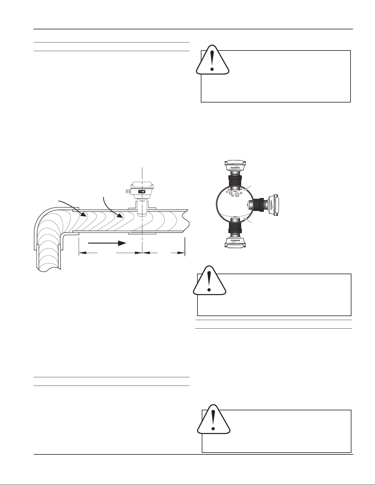
Faster Flow
Causes Meter
Distorted
To Read High
Flow Prole
10X
Distorted Flows
5X
Although EX800-Series PVC meter tees are supplied with some
straight pipe, additional straight pipe should be added to meet
straight pipe recommendations. It is not advisable to connect
a ow-disturbing device (e.g. valve or elbow) directly to the end
of these ttings.
A PVC tting is usually installed by solvent welding. The
stainless steel and brass meter ttings have female pipe
threads, requiring the appropriate male threaded ttings.
Saddle or weld ttings (3” and above) require a hole to be cut
in the pipe. Recommended hole size is 1-3/4”.
Meter Installation
After the meter tting is installed in the pipeline, the meter
can be installed in the tting. After noting the direction of the
ow arrow, press the meter into the tting as far as it will go.
Retain the meter in place by inserting the U-clip. The pin can
be installed from either side. It may be necessary to rotate the
probe back and forth slightly to start the pin into the slots on
the probe. Slide the pin in as far as it will go.
Horizontal (3 o’clock or 9 o’clock position) is the preferred
installation orientation, since it improves low-ow performance
and avoids problems with trapped air and sediment. (See
Orienting the Meter diagram below.) Bottom (6 o’clock), top
(12 o’clock), and vertical pipe installations are all acceptable if
required by the piping layout.
Fair
Unacceptable if pipe
contains air
Air bubbles
Best
Position
Sediment
Fair
Unacceptable if pipe
contains sediment
Orienting the Meter
Caution: Never remove the U-clip retainer when
the pipe is under pressure. Always remove
pressure from the pipe before you attempt to
remove the meter. Removal under pressure may result in
damage or serious injury.
Chemical Injection or Fertigation
When any magmeter, by any manufacturer, is used in a
chemical injection application (including fertigation), the
chemical injection point must be placed downstream of the
magmeter OR far enough upstream for complete mixing to
occur before the uid reaches the meter. When unmixed
chemical or fertilizer alternates with water passing through the
meter, the rapid changes in conductivity may cause sudden
spikes and drops in the meter’s reading, resulting in inaccurate
measurement. The magmeter will restabilize, however, with a
steady ow of uid of uniform conductivity.
Caution: In chemical injection or fertigation
applications, install chemical injection point
downstream of magmeter, or far enough
upstream to allow complete mixing of uids
before the meter.
Seametrics • 253.872.0284 • www.seametrics.com
Page 5
Page 6

Straight Pipe Recommendations (X = diameter)
Reduced Pipe
EX800 SERIES INSTRUCTIONSINSTALLATION
5X10X
Two Elbows In Plane
Two Elbows, Out Of Plane
Expanded Pipe
20X
20X
5X10X
5X
5X
Page 6
30X
Spiral Flow
Propeller Meter
20X
Swirling Flow
Partially Open
Buttery Valve
Seametrics • 253.872.0284 • www.seametrics.com
Page 7

INSTALLATION
Full Pipe Recommendations
Allows air pockets to form at sensor Ensures full pipe
EX800 SERIES INSTRUCTIONS
Better InstallationPossible Problem
Better InstallationPossible Problem
Post-valve cavitation can create air pocket Keeps pipe full at sensor
Better InstallationPossible Problem
Air can be trapped Allows air to bleed off
Caution: These ow sensors are not recommended for installation
downstream of a boiler feedwater pump where installation fault may
expose the ow sensor to boiler pressure and temperature. Maximum
recommended temperature is 130°F (Plastic), 200°F (Metal).
Seametrics • 253.872.0284 • www.seametrics.com
Page 7
Page 8

ELECTRICAL CONNECTIONS
EX800 SERIES INSTRUCTIONS
General Electrical Guidelines
• Whenever possible avoid running control cables in the
same conduit with or bundled with AC power.
• Using shielded cable, be sure to connect shield to ground
at power supply end of the cable.
• Avoid routing ow sensor cables in close proximity to a
variable frequency drive.
• Recommended power and output wiring is shielded
twisted pair 18-22 AWG control cable.
• Recommended voltage is 12-24 Vdc. Note that
unregulated power supplies can vary from nameplate
voltage by a considerable amount, especially with AC
line voltage uctuation. Therefore 24V power supplies
must be regulated.
See the Connections diagrams on the following pages for the
appropriate terminals.
Power
A 12 - 24 Vdc power supply capable of at least 250 mA current
output is needed.
Output
Forward Flow Output: This open-collector isolated output does
not supply power. This pulse is generated in the forward ow
direction on the standard unit. (Reverse ow output is available
as an option). Note: This output is limited to 6 mA at 30 Vdc
maximum.
Reverse Flow Output: Reverse ow output is available as
an option. This open-collector isolated output does not supply
power. It functions like a polarity-sensitive switch closure. Note:
This output is limited to 6 mA at 30 Vdc maximum. Grounding
Guidelines:
Grounding Guidelines
For best results, use a good quality earth ground, such as
metallic water piping or a driven ground, to ensure a good
connection to earth ground and good noise suppression.
If the ow sensor is installed in metallic piping, for optimum
connection clamp wire to the piping a short distance to one
side of the ow sensor using an electrical grounding clamp.
Connect the wire to the earth ground and to one of the housing
screws.
For Non-Metallic Pipe: Connect one to the housing screws by
wire to a good earth ground, such as metallic water piping or a
rod driven into the ground.
EX meters are usually unaffected by moderate levels of
electrical noise. In some applications performance may be
improved by taking the following steps:
• Use shielded twisted pair cable (Belden 8723 or
equivalent above ground or Alpha 35482 or equivalent
burial).
• Clamp a ferrite bead (Steward 28A2029-OAO or
equivalent) on meter signal/power wire within 3/4”
of the meter strain relief (tape or tie wrap in place if
necessary). See diagram below.
• IMPORTANT - Connect the cable shield ground
wire to ground, ONLY at power supply end of cable.
Place Ferrite Bead Here
Housing
Screw
Earth
Ground
Caution: The EX800 has a strong start and
run current. When using solar panels and
VRSLA batteries as a power source, use
caution to insure the EX-series sensor has
the -50 Low-power Option and that all Seametrics
products on the power circuit receive sufcient voltage and current under all conditions. Failure to do so
will lead to unreliable operation and possible damage
to the unit/s. Please reference the technical bulletin,
‘Solar and Battery-Power Guidelines’ available on our
website: www.seametrics.com
Page 8
Seametrics • 253.872.0284 • www.seametrics.com
Metallic Pipe
Grounding
Clamp
Grounding Diagram
Page 9

CONNECTIONS DIAGRAMS
+
_
+
_
00
9
8
7
6
5
4
3
2
1
00
9
8
7
6
5
4
3
2
1
00
9
8
7
6
5
4
3
2
1
00
9
8
7
6
5
4
3
2
1
+
_
S
+
_
+
_
+
_
+
+
_
_
+
_
+
+
_
_
+
_
+
_
Counter or PLC
EX800 SERIES INSTRUCTIONS
EX-SERIES
Power
12 - 24 Vdc
COUNTER OR PLC
Forward Output
(open collector)
See Dual FT430/440 Diagram for an
Reverse Output
(Option -15 only)
example of bidirectional connections.
Max. 6 mA, 30 Vdc
Max. 6 mA 30 Vdc
DIGITAL INPUT
AO55 4-20 mA Output
AO55
24 Vdc Power
Red
EX-SERIES
Black
Power
Forward Output
Reverse Output
(Option-15 only)
Green
White
+
–
Sensor
FREQUENCY
4-20 mA
24 Vdc Power
Black
Red
4-20 mA
See Dual FT430/440 Diagram for an
example of bidirectional connections.
FT520 Controller
Pulse
Out
See Dual FT430/440 Diagram for an
example of bidirectional connections.
FT520
24 Vdc Power
Black
+12V
SEN1
Green
G
SEN2
White
Seametrics • 253.872.0284 • www.seametrics.com
EX-SERIES
Red
Power
Forward Output
Reverse Output
+
(Option-15 only)
–
Page 9
Page 10

FT430/440 Display and Proportional Feed
+
+
_
_
+
_
+
_
+
_
+
_
+
_
S
+
_
+
_
+
_
Power
Pulse
Out 2
Sensor
Input
Pulse
Out 1
(Scaled)
(Scaled)
_
EX-SERIES
+
Power
_
Forward Output
Reverse Output
(Option-15 only)
See Dual FT430/440 Diagram for an
example of bidirectional connections.
FT440 DISPLAY AND 4-20 mA Output
+
_
+
_
Black
24 Vdc Power
Red
Green
White
EX800 SERIES INSTRUCTIONSCONNECTIONS DIAGRAMS
FT430/440
(430 = Pass-Thru
440 = Scaled)
+
Power
_
+
Pulse
Out 2
_
+
To
Proportional
Feed
Metering
Pump
Sensor
Input
_
S
+
_
+
Pulse
Out 1
(Scaled)
FT440
EX SERIES
Power
Forward Output
Reverse Output
(Option-15 only)
See Dual FT430/440 Diagram for an
example of bidirectional connections.
Red
Black
Black
24 Vdc
Power
4-20 mA Device
(e.g. pump, PLC)
24 Vdc
Power
Green
White
Black
Red
Dual FT430/440 Displays (Example of Bidirectional Connection)
Black
(Scaled)
Pulse
Out 1
Sensor
Input
+
+
_
+
Pulse
Page 10
Out 2
(430 = Pass-Thru
440 = Scaled)
_
S
_
+
_
Power
Seametrics • 253.872.0284 • www.seametrics.com
Red
EX-SERIES
White
Green
(Option-15 only)
Power
Forward Output
Reverse Output
24 Vdc
Power
Black
Red
Green
White
Power
Sensor
Input
_
+
_
S
+
FT430/440FT430/440
(430 = Pass-Thru
440 = Scaled)
Pulse
Out 2
_
+
_
+
Pulse
Out 1
(Scaled)
Page 11

CONNECTIONS DIAGRAMS
+
_
S
+
+
_
_
+
_
+
_
+
_
S
+
_
+
_
+
_
Power
Pulse
Out 2
Sensor
Input
Pulse
Out 1
(Scaled)
(430 = Pass-Thru
440 = Scaled)
DL76 Data Logger
EX800 SERIES INSTRUCTIONS
DL76
Power
Forward Output
Reverse Output
(Option-15 only)
See Dual FT430/440 Diagram for an
example of bidirectional connections.
FT430/440 and DL76
EX-SERIES
Power
Forward Output
EX-SERIES
24 Vdc
Power
Red
Black
Green
White
Black
Red
12-24 Vdc
Green
White
Sensor
Input
Power
DL76FT430/440*
Sensor
Input
White
Green
Reverse Output
(Option-15 only)
See Dual 430/440 Diagram for an
example of bidirectional connections.
* Note on FT440
The FT440 has Scaled Pulse Output only –
6.5 pulses/second maximum. Pulse Output 1 or
Pulse Output 2 can be used with DL76.
Seametrics • 253.872.0284 • www.seametrics.com
Page 11
Page 12

OPERATION & MAINTENANCE
10031295
EF81T-P200
K:158.42
EX800 SERIES INSTRUCTIONS
Zero Adjustment
When the EX800-Series meter is powered up and there is no
ow, there should be no output pulses (or, if connected to the
FT430/440, ow rate should read “0”). If there are pulses,
it may be necessary to adjust the ow meter under no-ow
conditions after it has been installed. This should only be
done if the indicated ow is low, near the lower cutoff.
Status
LED
Zero
Adjust
Pins
Reverse Output Option
unauthorized repair
Warranty is void if
is attempted!
Max. 6mA
30Vdc
3 4 5 6 2 1
Forward
Output
- + -
+
Power
12-24Vdc
Status
LED
Zero
Adj
Zero Adjustment
NOTICE
To perform the adjustment, after determining that there is a
full pipe with no ow, short between the two pins marked “Zero
Adjust”. A red LED light will come on for approximately 50
seconds and then go out. The zero adjustment is completed.
Electrode Coating
Grease or other adhering, non-conductive materials can stop
ow detection if the electrodes become heavily coated. To clean
the electrodes, remove the sensor from the pipe and gently
scrub the electrodes (three silver bumps) on the reading face
of the ow sensor. A mild soap (dish washing liquid for example)
can be used to aid the cleaning process.
Calibration (“K-Factor”)
The K-factor represents the actual number of pulses per gallon
the meter produces during a ow test. This number can be
entered into your electronic control to make it read properly.
If the EX800-Series meter is ordered with a tee tting, it is
factory-calibrated in the tting and the K-factor is indicated on
the side of the tting (see diagram).
Find your K-Factor Here
Minimum Flow
As with any other ow sensor, there is a rate below which the
EX800-Series sensor cannot read. Check the table below for
the minimum ow rate detectable by the sensor for a given
pipe size.
Flow Rate (GPM)
Nominal
Pipe Size
Min
@ 0.28 ft/sec
Max
@ 20 ft/sec
1” 1-1/2” 2” 3” 4” 6” 8” 10” 12”
0.7 1.5 2.7 6 11 25 44 69 99
49 110 196 440 783 1760 3130 4900 7050
Presence of Flow Indication. To assist in troubleshooting,
the “Status LED” has two blinking modes in normal operation.
When there is no ow detectable by the meter (below minimum
threshold) the LED blinks every 8.0 seconds. When there is
detectable ow, the same indicator blinks every 3.0 seconds
(Pulses are being output when indicator is blinking every 3
seconds).
Filtering
The software of the EX800-Series lters out electrical noise
and averages sudden variations in the ow to smooth the
output. It takes a matter of seconds for the ow sensor to get
up to full output when it is powered up or when ow begins.
If the EX800-Series meter is ordered with a saddle or weldolet
tting, nd your K-factor in the chart below.
K-Factors: Saddles & Weldolets
3” 4” 6” 8” 10” 12”
Schedule 40 70.397 40.985 18.120 10.474 6.674 4.709
Schedule 80 78.748 45.360 20.084 11.495 7.322 5.184
Stainless
Steel (10S)
Stainless
Steel (40S)
Copper
Tubing (L)
Copper
Tubing (K)
Brass Pipe 70.672 41 . 517 17.778 10.445 6.674 4.661
Duct. Iron
(Class 52)
NOTE: K-factors are in pulses/gallon. For pulses/liter, divide by 3.785
62.385 36.626 16.510 9.642 6.173 4.373
70.397 40.985 18.130 10.497 6.674 4.661
76.371 43.552 19.513 11.201 7.230 5.016
78.371 44.638 20.223 11.622 7.500 5.239
57. 376 37.320 16.915 9.503 6.197 4.325
Page 12
Seametrics • 253.872.0284 • www.seametrics.com
Page 13

EX800 Parts List
1
2
3
8
EX800 SERIES INSTRUCTIONSOPERATION & MAINTENANCE
EX800 Series Parts
4
7
1 Upper housing
assembly
2 Housing Gasket 100411
3 Lower housing Not eld replaceable
4 Housing screw/washer
kit (4 each)
7 Strain relief kit, large
(includes 1)
8 Sensor assembly Not eld replaceable
100662
103702
103700
Seametrics • 253.872.0284 • www.seametrics.com
Page 13
Page 14

TROUBLESHOOTING
Problem Probable Cause Try...
No pulse output Pipe not full Check plumbing
Below minimum ow cutoff Check the presence of ow LED (see page 12)
Unit not grounded Connect to earth ground (see page 8)
Excessive electrical noise Check for proper electrical wiring
No power Check for power across power input terminals
Power reversed Reverse connections
Flow reversed Note ow direction arrow,
reverse direction of meter
EX800 SERIES INSTRUCTIONS
Output connections reversed Change output connections
Fluid conductivity <20 microSiemens/cm Select another ow meter
Output pulses incorrect Missing or incorrect ground wire Check for proper ground
Excessive electrical noise Check for proper electrical wiring
Fluid conductivity <20 microSiemens/cm Select another ow meter
Empty pipe Check for full pipe or install meter in the
vertical position
Not enough straight pipe Check for ten diameters upstream AND ve
diameters downstream
Jumpy reading Rapidly changing conductivity (in chemical
injection or fertigation applications)
Install chemical injection line downstream of
magmeter (or far enough upstream to allow
complete mixing of uids before meter)
Page 14
Seametrics • 253.872.0284 • www.seametrics.com
Page 15

EX800 SERIES INSTRUCTIONSNOTES
Seametrics • 253.872.0284 • www.seametrics.com
Page 15
Page 16

Seametrics • 19026 72nd Avenue South • Kent, Washington 98032 • USA
(P) 253.872.0284 • (F) 253.872.0285 • 1.800.975.8153 • www.seametrics.com
LT-65200203r1.0-20160225
2/25/16
 Loading...