

Page 1
EM 100/102
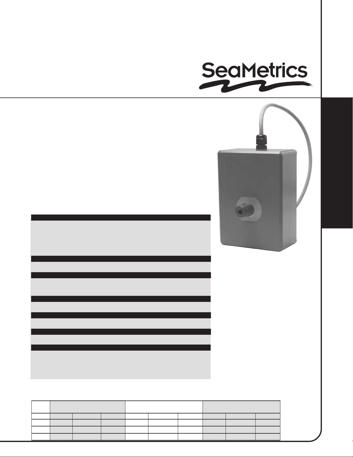
LOW-FLOW MAGNETIC FLOW METER
INSTRUCTIONS
EM 100/102 - 025
EM 100/102 - 038
EM 100/102 - 050
GENERAL INFORMATION
The EM100 is a 24 VDC-powered electromagnetic flow meter with
chemically-resistant plastic wetted parts, in nominal maximum flow rates of
4, 11, and 30 liters per minute. It uses bipolar DC technology at a frequency
high enough to allow for measurement of pulsating flows from diaphragmtype chemical metering pumps. All electronics are contained in a single
compact, chemical-resistant housing. This configuration, combined with the
standard pulse and analog outputs, makes the EM100 well suited for OEM
applications. Other applications include remote monitoring of chemical
volume or rate using a computer or PLC.
EM100/102 LOW FLOW
MAGNETIC FLOW METER
INSTRUCTIONS
SPECIFICATIONS
MATERIALS
Wetted Materials -
Housing -● ABS
POWER
ACCURACY
MAXIMUM FLUID TEMPERATURE
MAXIMUM PRESSURE
MINIMUM CONDUCTIVITY
OUTPUTS
●
Body: Kynar™ PVDF
●
Electrodes: Platinum over titanium
●
Internal Seals: Viton™
●
12-24 VDC, 180 mA
●
+/-1% of reading, above 10% of full scale
●
+/-3% of reading, below 10% of full scale
●
185º F
●
150 PSI (@ 75º F)
●
20 microsiemens
●
Frequency opto isolated 1000 pulse/liter (3785 p/g)
●
Optional 4-20 mA opto isolated passive
FLOW RANGE
SIZE NOMINAL FULL SCALE MIN. FOR 1% ACCURACY LOW FLOW CUTOFF
L/MIN. GAL./MIN. GAL./HR. L/MIN. GAL./MIN. GAL./HR. L/MIN. GAL./MIN. GAL./HR
-025 3.8 1 60 .38 0.1 6 .04 .009 .54
-038 11 3 180 1.1 .3 18 0.1 .025 1.5
-050 30 8 480 3.0 .8 48 .25 .065 3.9
1- 800-975-8153
Page 2

INSTALLATION
The EM100 can be supported by its piping connections
if the piping is rigid and there is no vibration.
Alternatively, the grounding studs can be used for
mounting by inserting them through pre-drilled holes.
Note the centerline distance in the dimensional
drawing below.
MOUNTING
CAUTION: Although this meter has
an empty pipe detection function,
under certain conditions of empty
or partially-full pipe the meter may
read a flow when there is none.
If this is a hazardous condition,
mount the meter in such a way as to ensure the meter
will always be full of liquid.
Table 1: Fittings and Length
Size
-025
-038
-050
Fittings
3/8 NPT
3/8 NPT
1/2 NPT
L (Length)
3.75
3.75
4.90
MAGNETIC FLOW METER INSTRUCTIONS
L
MALE PIPE FITTING,
PVDF PLASTIC,
2 PLACES;
SEE TABLE 1
EM 100/102 SERIES
ABS HOUSING
3.75
2.00
6 FT. LONG
CONTROL CABLE,
6 CONDUCTOR
.83
www.seametrics.com
#10-24 STUDS (2), 316
.60
12 FT. LONG GROUNDING
WIRE WITH LUGS (SUPPLIED)
5.70
2.48
.62
2.000
2 EACH #10 LOCKWASHERS
& #10-24 HEX NUTS (SUPPLIED)
Page 3

PIPING
Metallic pipe or tube, or plastic tubing can be used with the meter. The -025 and -038 meters have 3/8 NPT male
pipe fittings, and the -050 has 1/2 NPT male pipe fittings. For plastic tubing, use female NPT x tubing adaptors. In
installations exposed to vibration, using the piping as the sole support for the meter is not recommended, particularly
on the smaller sizes.
If metal piping is used, ground connections from the grounding studs on the bottom of the unit to both inlet and outlet
pipes provide the best results in metering accuracy. This does not apply to plastic tubing. A minimum of 1” of straight
pipe run is recommended on the inlet side of the meter. Straight run is not necessary on the outlet.
CONNECTIONS
Power and signal connections are provided by the single 4 or 6-conductor cable, and are color-coded. See the “wiring
connections” chart. In addition, it is necessary for proper operation to ground the unit to a good quality earth ground.
Use the 12 ft. grounding wire supplied with the unit, or if necessary, a longer wire attached to one or both of the
grounding studs.
EM 100/102 SERIES
MAGNETIC FLOW METER INSTRUCTIONS
WIRING
CONNECTIONS
RED + 12 to 24 VDC Power
BLACK - Power
GREEN + Pulse Output Isolated
WHITE - Pulse Output Isolated
ORANGE + 4-20 mA Isolated
BLUE - 4-20 mA Isolated
}
Optional
Page 4

OPERATION
When the newly-installed meter is first powered up, particularly if it has been dry prior to start up, it can take from
a few seconds to a minute for the signal to stabilize. In normal operation, keeping the meter filled with fluid is
recommended to prevent this delay. An empty pipe detection feature will normally respond to lack of liquid in the
pipe, and will register zero flow, but under certain rare conditions it is possible for this feature to fail to recognize
the empty pipe. See the warning under “Mounting” regarding this possible problem.
The optional 4-20 mA signal outputs 4 mA at zero flow and 20 mA at maximum rated flow. The standard pulse
signal is a 50% duty cycle pulse set at 1000 pulses/liter (3785 pulses/gallon).
EM100/102 TROUBLESHOOTING GUIDE
Problem Possible Causes Possible Solutions
Analog output at 0 mA
EM100/102 LOW FLOW
MAGNETIC FLOW METER
INSTRUCTIONS
Analog output is 4 mA
with flow
No pulse output
Flow rate incorrect
No loop power
Unit not grounded
Flow reversed
Reversed output connections
Not grounded
Reversed flow
Missing or incorrect ground wire
Fluid conductivity <20 uS/cm
Empty pipe
4-20 mA loop needs an external
power supply - if missing, add it
Connect to earth ground
Note flow direction arrow, reverse
direction to match
Change output connection
Connect to earth ground
Change flow direction
Check for proper grounding
Select other flow meter
Install meter in vertical position
Revised 8/03
www.seametrics.com
19026 72ND AVE SOUTH, KENT, WA 98032 USA
(P) 253.872.0284 (F) 253.872.0285
WWW.SEAMETRICS.COM 1.800.975.8153
LT-11748-A
 Loading...